

Page 1
Machining &
Installation
Instructions
Please carefully read instructions before installing interlocks.
D-M-E IN2 INnovative INterlocks
MOLD BASE MACHINING
1. Four (4) D-M-E IN2 INnovative INterlocks must
be used on each mold. When in operation, the
interlocks contact the edges of the machined
pocket to maintain parting line alignment. The
socket head cap screws are only used to retain
the interlocks to the mold base.
2. It is recommended that the mold base assembly
be clamped together and machined as an
assembly to insure proper parting line alignment.
3. Machine the interlock pockets accurately in
assembly. Locate each interlock pocket on the
centerline of the mold. The centerline location
is critical to avoid misalignment problems
which could result from uneven thermal
expansion of the separate mold halves.
4. Mark the mating interlocks to insure that the
interlocks remain as sets.
5. Mount the IN2 female interlock on the
half of the mold which will have the highest
operating temperature. Normally, this will
be the “A” side of the mold. This is important
to insure that the male interlock does not
grow larger than the female interlock if
uneven mold temperatures occur.
6. Torque the socket head cap screws to:
4.5 ft.lbs for #8-32 socket head cap screws
7.5 ft.lbs for #10-32 socket head cap screws
16.5 ft.lbs for 1/4-20 socket head cap screws
7. After installation, open and close the mold
on the bench and check to insure proper
alignment has been achieved.
8. Always maintain lubrication on the interlocks
to prevent galling.
9. Please carefully read instructions on other side
regarding installation of the inserts for IN2
INnovative INterlocks.
SIS-9999-3/05
ME-E09-0199-A
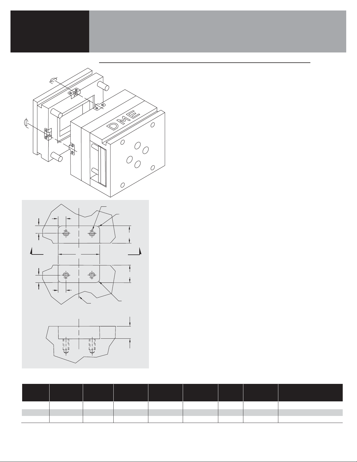
IN2 INnovative INterlock Dimensions
INTERLOCK
AB S
REPLACEMENT
SET*
W
HEIGHT HEIGHT
TR
SCREW THREAD INTERCHANGEABLE INSERTS**
ITEM NO. WIDTH FEMALE MALE DEPTH RADII LOCATIONS SIZE ITEM NO.
SIS150023 1.500 .875 .875 .500 .25 .250 #8-32 x .38 Deep SII15003
SIS200023 2.000 1.375 .875 .500 .25 .312 #10-32 x .44 Deep SII20003
SIS300023 3.000 1.875 .875 .750 .375 .375 1/4-20 x .50 Deep SII30003
*Sets include one (1) male,
one (1) female, two (2) inserts,
four (4) SHCS.
**Replacement Interchangeable Inserts
are sold in pairs.
PATENT PENDING
S
Y
S
THREAD SIZE
S
+.0002
-.0000
W
S
CENTERLINE
OF MOLD
R
+.005
-.000
A
Y
+.005
-.000
B
R
+.005
-.000
T
VIEW Y-Y
Page 2
Machining &
Installation
Instructions
D-M-E IN2 INnovative INterlocks
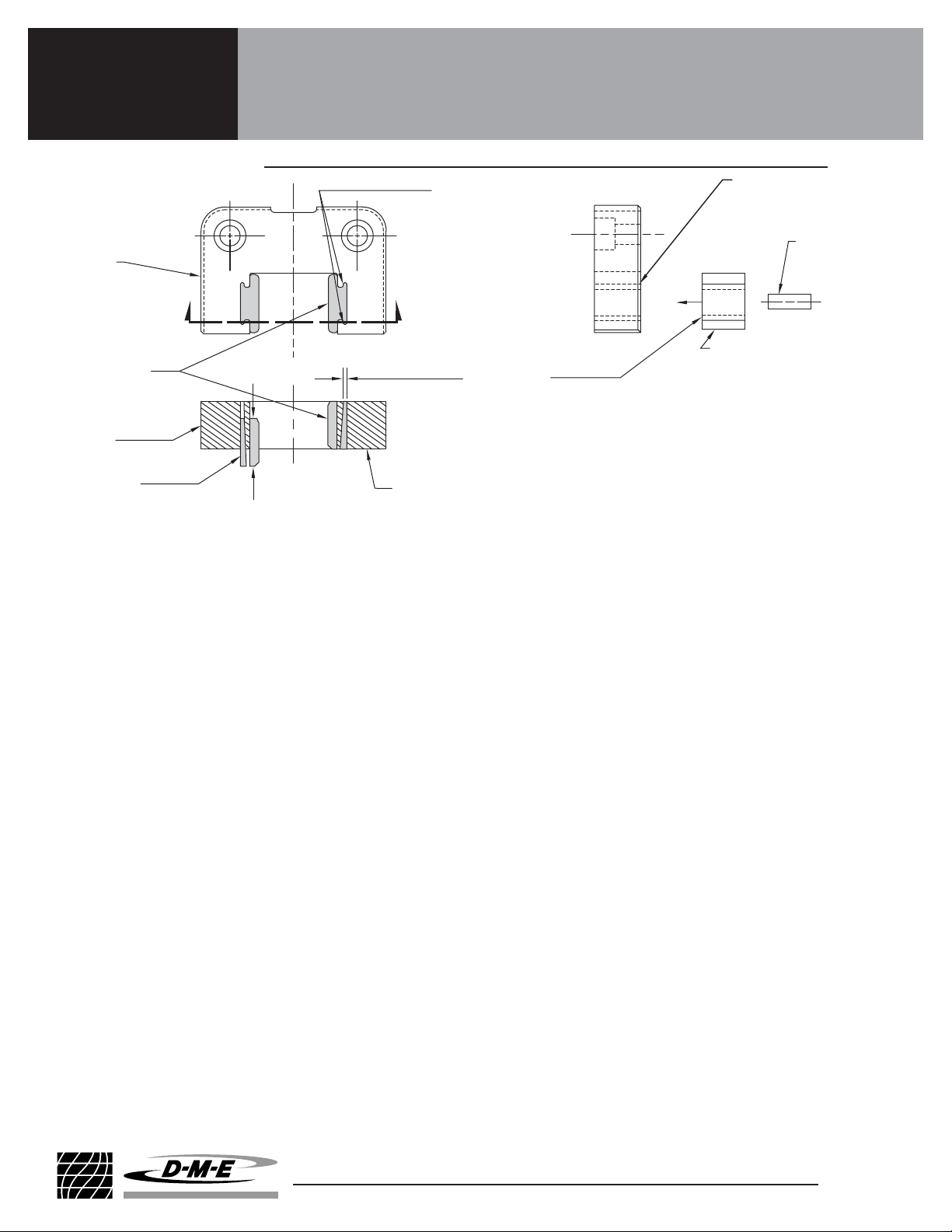
INSERT INSTALLATION
INSERT INSTALLATION
D-M-E INterchangeable INserts can only be installed from
the back of the female IN2 INnovative INterlock. The back of
the female interlock mounts against the mold (and is the side
opposite the counterbores for the socket head cap screws).
When the Interchangeable Inserts are properly inserted into
the female interlock they will be retained by the tapered
wedge of the Interchangeable Insert and the retaining taper
of the female interlock. Once installed in a mold, the mold will
insure that Interchangeable Inserts will be securely retained.
1. First, place the female interlock face down on a flat
surface with the back facing up.
2. Next, select a pair of IN2 INterchangeable INserts for
the appropriate size interlock for insertion into the female
interlock. Interchangeable Inserts of the same size are
truly interchangeable; any Interchangeable Insert of the
proper size can be inserted into the female interlock.
3. Inspect the tapered wedge on the Interchangeable
Insert to determine which end of the Interchangeable
Insert is the thin end of tapered wedge. The thin end
of the tapered wedge will be inserted into the female
interlock first (refer to above drawings for clarification).
4. Insert the thin end of the tapered wedge into the female
interlock from the back and slide the Interchangeable
Insert firmly into the female interlock. The Interchangeable
Insert should seat most of the way into the female interlock
by hand. The tapered wedge of the Interchangeable Insert
provides a slight interference fit with the retaining
wedge of the female interlock.
SIS-9999-3/05
ME-E09-0199-A
5. Now, place an aluminum rod against the Interchangeable
Insert and use a hammer to tap on the aluminum rod to
move the Interchangeable Insert until it is flush with the back
of the female interlock. Properly seated Interchangeable
Inserts will be .000 to .005 below the back surface of the
female interlock. Use an aluminum rod whose diameter is
small enough to make contact with only the Interchangeable
Insert and does NOT contact the small retaining wedges
on the female interlock.
6. Repeat this procedure for each insert.
7. The D-M-E IN2 INnovative INterlock is now ready
for installation on your mold. Please carefully read
instructions on other side regarding installation of
IN2 INnovative INterlocks on your mold.
INSERT REMOVAL
To remove an Interchangeable Insert from an IN2 INnovative
INterlock, the female interlock must be removed from the mold.
1. Place the female interlock on two aluminum blocks with
the front facing up. (The front face of the female interlock
is the side with the counterbores.) Position the two aluminum
blocks under the outer edges of the female interlock but
not under the Interchangeable Insert being removed.
2. Place an aluminum rod on the Interchangeable Insert and
use a hammer to tap on the aluminum rod. The Interchangeable
Insert has a tapered wedge which will release from the
retaining taper of the female interlock as the insert moves
down, allowing the Interchangeable Insert to drop free
from the female interlock. As previously indicated, use
an aluminum rod whose diameter is small enough to make
contact with only the Interchangeable Insert and does NOT
contact the small retaining wedges on the female interlock.
3. Repeat this procedure for each insert.
Please carefully read instructions before installing inserts.
PATENT PENDING
D-M-E Company World Headquarters 29111 Stephenson Highway, Madison Heights, MI 48071
U.S. 800-626-6653 • Canada 800-387-6600 • www.dme.net
FEMALE
INTERLOCK
TAPERED
WEDGE OF
INTERCHANGEABLE
INSERT
BACK OF
INTERLOCK
FEMALE
ALUMINUM
ROD
INSERT
INSTALLED
FEMALE
INTERLOCK
INSERT
PARTIALLY
INSTALLED
Z
REMOVE
INSERT
SECTION Z-Z
INSTALL
INSERT
Z
BACK OF
FEMALE
INTERLOCK
INSERT BEING
ALIGNED FOR
THIN END OF
TAPERED WEDGE
GOES IN FIRST
INSTALLATION
 Loading...