

Page 1
ME-0741-PS-554-D
08-08
375 SERIES EXTENDED
SPRUE GATE NOZZLE
REFER TO : MINI PRINT # 1800
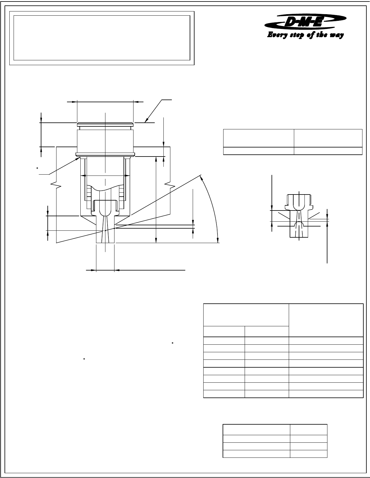
NOTE: Dimensions are shown in Inches.
INSTALLATION DATA
+0.001
2.001
0.250 MIN.
0.000
DIA.
ESG3/IS
MANIFOLD LINE
0.125 MIN.
NOTE:
Before installing a Extended Sprue Gate Nozzle, it is important to take
the nozzle's expansion factor into consideration. For best results, please
follow the information below
MACHINING DIMENSIONS
"N' Dia. (max.) "N' Dia. (min.)
Square Coil or Cast-In
1.625 1.437
Square Coil or Cast-In
0.030 X 45
CHAMFER
0.375 MIN.
AFTER CUT
For selection of gate diameter it is important to take into consideration the materials flow characteristics, shear rate of resin, molding conditions, fill time
requirements, gate vestiage, wall thickness and configuration of part to be molded. Situations requiring high injection velocities must be considered
when selecting small gate diameters. High injection rates may require larger gates due to shear heat build up (e.g. high weight thin wall applications).
See material manufactures literature for further information regarding material to be molded.
To compensate for the nozzle's growth when heat is applied, the linear
expansion of the nozzle (BE) at a given temperature must be added
to the nominal "A" dimension. The formula
boring depth (dimension "A" + BE).The tip of the nozzle will now be
flush with cavity line.
Formula for determining this expansion factor is as follows:
BE="A" dimension x 0.00000633 x (Nozzle set point temperature - 68
EXAMPLE: Given a 3 inch "A" dimension, with a nozzle set point
temperature of 500
BE = 3 x 0.00000633 x (500 - 68) = 0.008
Thus "A" + BE will be 3.008
Note:
The above information is only given as an example. variations may occur
based on mold configurations and cooling factor. In some instances it may
be necessary to obtain an empirical factor.
F:
"N"
DIA.
"A" + BE
BORE TO FIT TIP
"("T" DIA.) +0.0005 / -0.0000
below shows how to figure
F).
3
0
.
0
0.080 MIN.
°
NOZZLE SUB-ASSEMBLY
CATALOG NUMBER
SQ.COIL HTR. CAST-IN HTR.
EHA0008 CIA0008 2.750
EHA0009 CIA0009 3.250
EHA0010 CIA0010 3.750
EHA0011 CIA0011 4.250
EHA0012 CIA0012 4.750
EHA0013
EHA0014 CIA0014 6.750
EHA0015 CIA0015 7.750
0.375 MIN.
AFTER CUT
0.080 MIN.
"A" DIMENSION
FOR NOZZLE ASSEMBLY
5.750CIA0013
WIRING INFORMATION
Square Coil Heaters and Cast-In Heaters are supplied with 2"
prestripped 36" long leads.
Heaters are 240 VAC.
2 power leads are Multi Color. 1 ground lead is GREEN.
Thermocouple is "J" Type. Thermocouple is supplied with 36" leads.
1 T/C lead is WHITE and negative (
constantan (non-magnetic).
1 T/C lead is BLACK and positive (+)
iron (magnetic).
-)
SPRUE GATE TIP SUB-ASSEMBLY
CATALOG NUMBER "T" DIA.
EHT0019 0.500
EHT0020 0.750
EHT0021 1.000
NOTE: Nozzle Assembly requires Nozzle Sub-assembly and Tip-assembly.
Page 2
ME-0741-PS-554-D
08-08
375 SERIES EXTENDED
SPRUE GATE NOZZLE
INSTALLATION DATA
REFER TO : MINI PRINT # 1800
ESG3/IS
OPERATING & SERVICING INSTRUCTIONS
FOR 375 SERIES EXTENDED SPRUE GATE NOZZLES
All interchangeable nozzles are similar, and differ only in size and material flow
capacity. The information found below applies to the 375 Series Extended sprue
gate nozzles.
OPERATING PROCEDURE
The nozzles are supplied with a Square (Flat) Coil or Cast-In heater equipped with a
Type J Thermocouple.
It is recommended to use a D-M-E closed loop Temperature Controller for optimum
Temperature Control.
When starting the nozzle, set the temperature to 10% voltage if using in open loop
manual type or to 200
procedure will allow the heater to dissipate any moisture.
Make sure you maintain this start-up setting for 15 minutes.
Controller equipped with Step Smart ® , Smart Step ®
or other heater warm-up circuitry will change automatically.
It is essential to use controllers with the proper voltage and wattage capabilities.
The voltage and wattage of each heater is clearly marked on the heater tag.
Step Smart ®, Smart Start ® and DME ® are all registered trademarks
of DME Company.
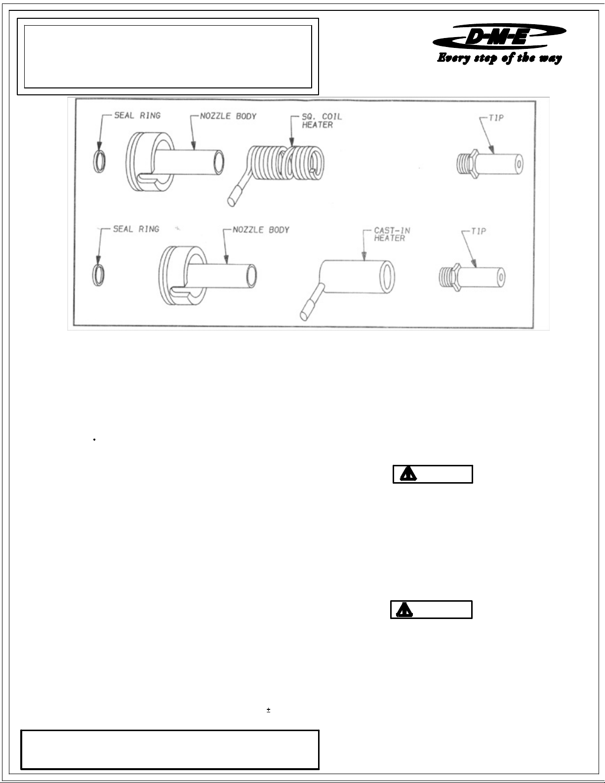
DISASSEMBLY PROCEDURE
1. Place the nozzle in a vice using "V" Block, then secure it firmly at the nozzle head.
2. For removal of tip from nozzle, a six point deep well socket is recommended. The
nozzle must be at processing temperature and the heater should be turned off
when removing tip counter-clockwise from the nozzle. If nozzle is still in the mold,
the nozzle must be "keyed" to prevent wire damages.
3. Tip must be cleaned of any material before reassembling.
4. Remove the heater using a Square Coil Heater wrench (Wrench is included with
replacement heater).
5. Cast-in heater may be removed if failure occurs and replaced with a square coil
heater. Follow assembly procedures for square coil heater.
ASSEMBLY PROCEDURE
1. Nozzle body must be cleaned of any material in the seal off area and threaded
areas before reassembling.
2. Install the heater using a Square Coil Heater wrench (Wrench included with
replacement heater). After the heater is installed, it should cover the entire length
of the nozzle body - stretch the heater by hand if necessary.
3. Apply an anti-seize compound on the tip threads.
4. Firmly screw the tip sub-assembly into the shank of the nozzle body. Tighten and
untighten two or three times making sure there is a good contact between the tip
and the shank. Torque the sub-assembly into the nozzle body using 30
For protection of the tip sub-assembly, a six point deep well socket is recommended.
D-M-E SHALL NOT BE LIABLE FOR MISUSE OR FAILURE TO FOLLOW THE ENCLOSED
INSTRUCTIONS AND SPECIFICATIONS. D-M-E HERBY TO DISCLAIMS ALL IMPLIED
WARRANTIES, INCLUDING MERCHANTABILITY AND FITNESS FOR A PARTICULAR
PURPOSE. IN NO EVENT SHALL D-M-E BE RESPONSIBLE FOR LOSS OF USE, REVENUE
OR PROFIT, OR FOR INCIDENTAL OR CONSEQUENTIAL DAMAGED.
F if using closed loop automatic type. In either case this
5 ft-lbs.
6. Careful attention should be taken to the heater / thermocouple leads as
damage could occur when working on nozzle assembly.
7. Seal ring for nozzle body must be replaced each time nozzle body and / or
manifold are removed to ensure seal off.
8. Wait a minimum of 5 minutes after set point has been achieved for sufficient
heat to transfer into the tip before molding.
IMPORTANT SAFETY INFORMATION
A hot-runner system includes electrical elements and may contain molten
plastic at elevated temperature and pressure. To avoid injury, exercise
caution by reading these instructions before servicing or operating the
system.
These instructions must be passed on to the end user where they should
be read before using this product. Failure to do so can result in serious
injury or death.
DANGER
Failure to comply will result in serious injury or death:
ELECTRICAL HAZARDS
Improper voltages or grounding can result in electrical shock. Use only
with proper voltage and a proper earth ground.
To avoid electrical shock, do not operate product when wet.
Do not operate this equipment with covers or panels removed.
To avoid electrical shock, turn off main power disconnect and lockout /
tag out before servicing this device. Do not connect temperature sensors to
electrical power. It will damage the product and it can cause fire, severe
injuries or even death.
If green ground wire present wire must be connected to the ground.
Do not rebend rigid leads. Rebending leads might result in damage to circuit.
Product might absorb moisture when cool. Use low Voltage or power to drive
out residual moisture before applying full power. Failure to do so may cause
damage to this product.
WARNING
Failure to comply can result in serious injury or death:
STORED ENERGY AND HIGH TEMPERATURE HAZARDS
This product maintains molten plastic at high pressure. Use caution when
operating and servicing the system.
Physical contact with molten plastic may result in severe burns. Proper
protective equipment, including eye protection, must be worn. This product
has heated surfaces. Use caution when operating and servicing the system
to avoid severe burns. Proper protective equipment should be worn.
D-M-E COMPANY
29111 STEPHENSON HIGHWAY
MADISON HEIGHTS
MICHIGAN 48071 USA
US 800-656-6656
CANADA 800-387-6600
www.dme.net
 Loading...