

Page 1
ME-06-0005-0011(A)
02-10 Catalog # BGMSIP
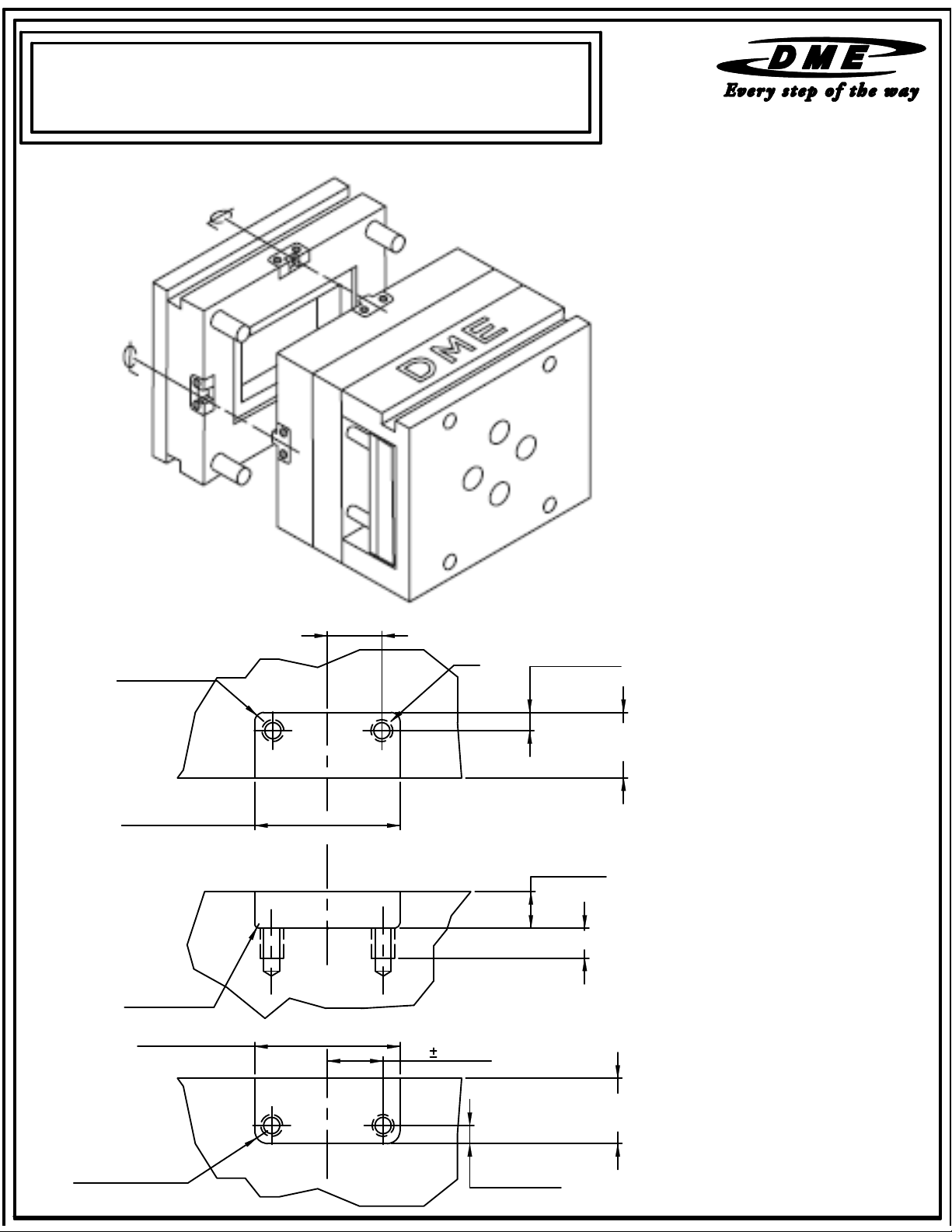
INSTALLATION DATA
FOR BLACK &GOLD METRIC SIDE INTERCHANGEABLE
INTERLOCKS
Please read carefully before installing components.
Dimensions Shown in mm
Unless otherwise specified,
Tolerances are:
0 +/-0.8
0.0 +/-0.3
0.00 +/- 0.13
0.000 +/-0.013
0.0
RF
-0.5
FEMALE POCKET
+0.02
WP
+0.01
CENTRAL
R
±0.1
WP
CENTRAL
(2)
(2)
+0.02
-0.01
E ±0.2(2)
C
L
C
L
E 0.2(2)
T
D ±0.2 (2)
+0.02
BF +0.01
+0.02
C +0.01
L MIN FULL THREAD
MALE POCKET
0.0
RM -0.5
(2)
C
+0.02
BM +0.01
L
D ±0.2 (2)
RECOMMENDED POCKET
SURFACE FINISH IS 1.6
m
in]Ra
mm [63
Page 2
ME-06-0005-00011(A)
0
b
02-10 Catalog # BGMSIP
INSTALLATION DATA
FOR BLACK &GOLD METRIC SIDE INTERCHANGEABLE
INTERLOCKS
Please read carefully before installing components.
Installation Instructions:
1. Four D-M-E Side Interlocks must be used in each mold application. When in operation,
the interlocks contact the edges of the machined pocket to maintain Parting line alignment.
The cap screws are only utilized to retain the interlocks to the mold base.
2. To maintain alignment, it is recommended that the mold base assembly be clamped
together and machined in assembly to insure proper parting line alignment.
3. Machine the interlock pockets accurately in assembly. Locate each interlock pocket on the
centerline of the mold. The location is critical to avoid misalignment problems which
could result from uneven thermal expansion of the separate mold halves.
4. Mount the female interlock on the half of which will have the highest operating
temperature. Normally, this will be the “A” side of the mold. This procedure is critical to
insure that the male interlock does not grow larger than the female interlock if uneven
mold temperatures are present.
5. Place
oth male and female interlocks into the pockets while the mold is clamped together
then thread in and tighten screws.
6. Torque the mounting SHCS to:
x 27 N x m [19.8 FT x LBS] for M6-1.0 SHCS
x 130 N x m [95.5 FT x LBS]for M10-1.5 SHCS
7. After installation, open and close the mold on the bench to insure proper alignment.
8. For “shuttle” molds repeat steps 2 to 7 for each interchangeable “B” side.
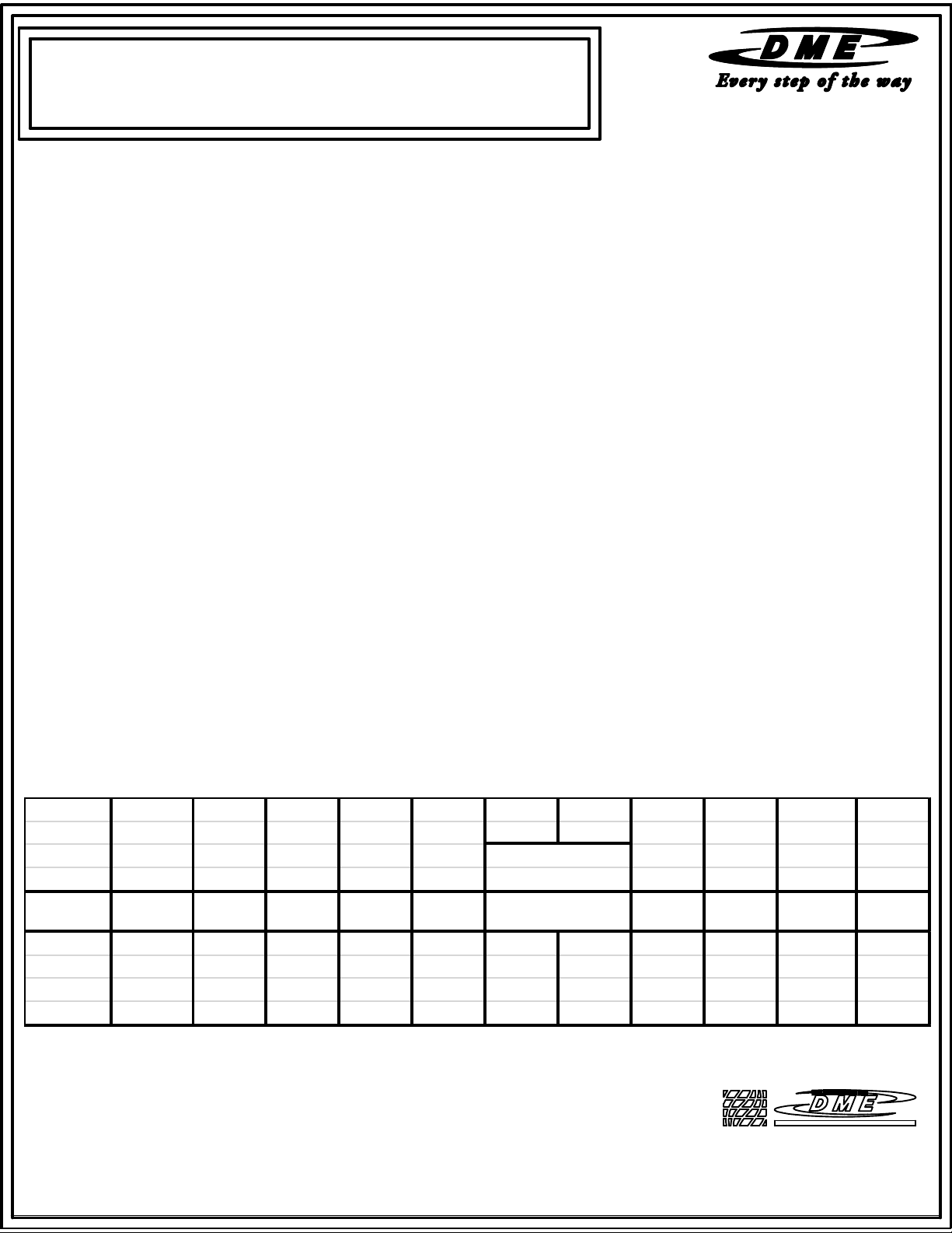
CAT # CAT #
MALE FEMALE MALE FEMALE POCKET POCKET THREAD
BGS05016M BGS05016F 50.00 21.50 21.50 16.00 11.00 17.00 5.0 0.2 M 6x20 Lg 12.0
BGS07519M BGS07519F
BGS10019M B GS10019F 100.00 45.00 45.00 19.00 22.00 35.00 5.0 0.5 M 10 x 25 Lg 18.0
BGS12525M BGS12525F 125.00 45.00 45.00 25.00 22.00 42.00 5.0 1.0 M 10 x 30 Lg 17.0
NOTE: Dimensions are in mm.
WP
POCKET
LENGTH
+0.02
+0 .0 1
75.00
BM BF C D E RF/RM R T L
P OCKET P OCKET P OCKET RA DIUS RA DIUS SCREW LENGT H
WIDTH WIDTH DEPTH SIZE MIN
+0.02
+0 . 0 1
36.00 36.00 19.00 18.00 25.00 5.0 0.5 M 10 x 25 Lg 18.0
+0.02
+0 .0 1
+0.02
+0 .0 1
SCREWS
LOCA TIONS
+/-0.2
+
-0.5
+/ - 0 . 1
29111 STEPHENSON HIGHWAY
MADISON HEIGHTS
MICHIGAN 48071 USA
US 800-656-6656
CANADA 800-387-6600
www.dme.net
 Loading...