

Page 1
ME-0725-PS-216-B AFIP/ID
09-08
AUTO-FIXED INTEGRAL HEATER
MICRO PROBES
Please read carefully before installing probes
REFER TO : MINI PRINT # 1700
NOTE: PROBE DISCOLORATION
Each Integral Heater probe sold by D-M-E is pretested.
This procedure discolors the outer surface of the probe,
but in no way alters its performance or dimensions
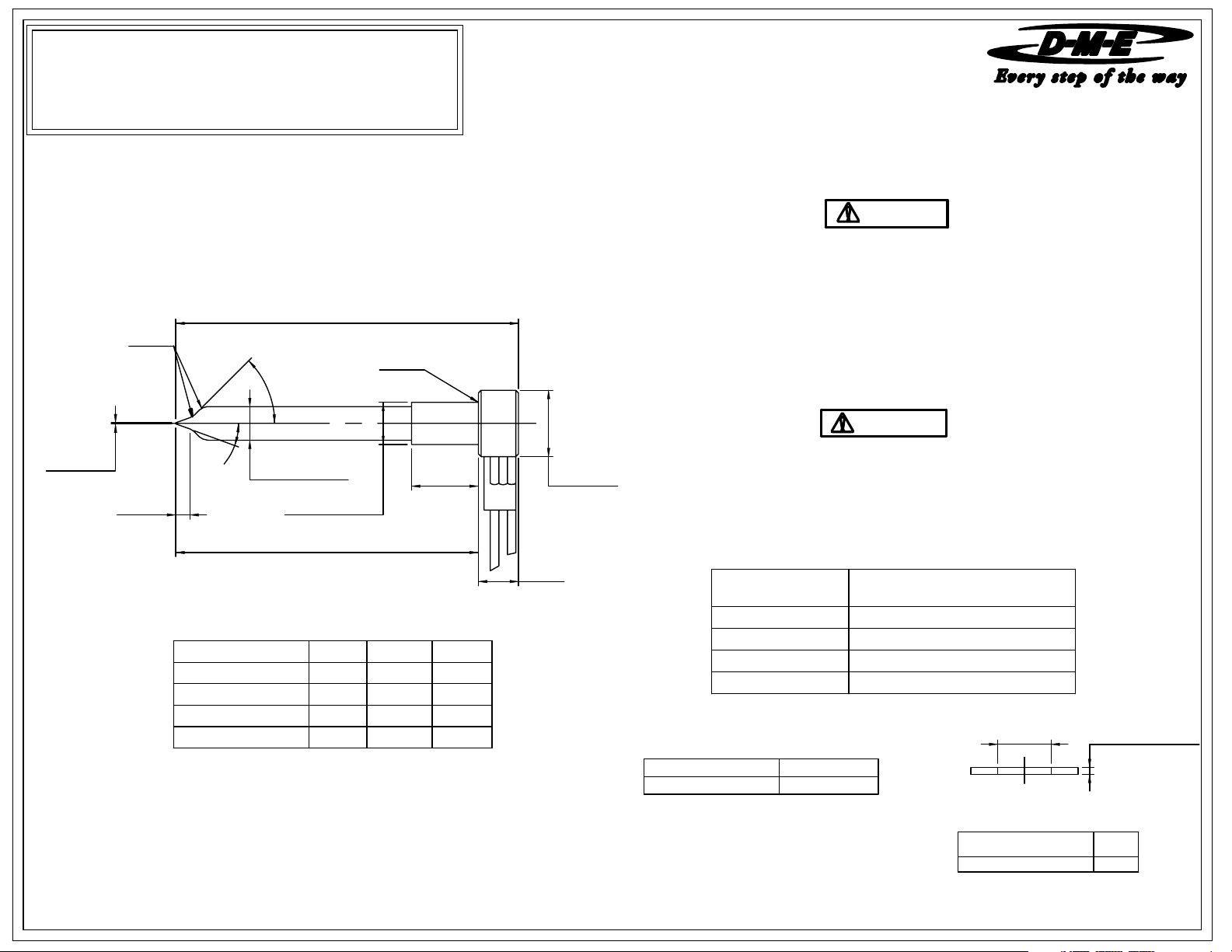
AUTO-FIXED " INTEGRAL HEATER" MICRO PROBES
(240 VAC, T/C TYPE J, 48" LEADS)
MATERIAL, AISI D-2 STEEL OR EQUIVALENT HARDNESS, 50-55 RC
A
0.125 R.
0.030 R.
0.625
DIA.
0.005 DIA.
0.157
20°
4
5
°
0.000
0.312 -0.001
0.394
DIA.
0.000
-0.001
B
0.620 DIA.
IMPORTANT SAFETY INFORMATION
A hot-runner system includes electrical elements and may contain molten
plastic at elevated temperature and pressure. To avoid injury, exercise
caution by reading these instructions before servicing or operating the
system.
These instructions must be passed on to the end user where they should
be read before using this product. Failure to do so can result in serious
injury or death.
DANGER
Failure to comply will result in serious injury or death:
ELECTRICAL HAZARDS
Improper voltages or grounding can result in electrical shock. Use only
with proper voltage and a proper earth ground.
To avoid electrical shock, do not operate product when wet.
Do not operate this equipment with covers or panels removed.
To avoid electrical shock, turn off main power disconnect and lockout /
tag out before servicing this device. Do not connect temperature sensors to
electrical power. It will damage the product and it can cause fire, severe
injuries or even death.
If green ground wire present wire must be connected to the ground.
Do not rebend rigid leads. Rebending leads might result in damage to circuit.
Product might absorb moisture when cool. Use low Voltage or power to drive
out residual moisture before applying full power. Failure to do so may cause
damage to this product.
WARNING
Failure to comply can result in serious injury or death:
STORED ENERGY AND HIGH TEMPERATURE HAZARDS
This product maintains molten plastic at high pressure. Use caution when
operating and servicing the system.
Physical contact with molten plastic may result in severe burns. Proper
protective equipment, including eye protection, must be worn. This product
has heated surfaces. Use caution when operating and servicing the system
to avoid severe burns. Proper protective equipment should be worn.
CATALOG NUMBER A DIM. B DIM.
AFIP3-310-90
AFIP3-360-90
AFIP3-410-90 4.095
3.095 2.720 110
3.595
3.220 130
Note: Dimensions shown in Inches.
WATTS
1503.720
1704.2204.595AFIP3-460-90
0.375
ITEM
ADJUSTMENT RING
REGISTER RING
GATE INSERT
THERMOCOUPLE
(Installed in probe)
LEAD LENGTHCATALOG NUMBER
AFIP3-310-90 THRU AFIP3-460-90
48"TC-9900
USED WITH
TC-9900THERMOCOUPLE
RAF3-062
AFRR-03N
AFGI-03N
ADJUSTMENT RINGS
(Packaged with all probes)
I.D.
0.062
(GRIND TO SUIT)
I.D.CATALOG NUMBER
0.456RAF3-062
Page 2
ME-0725-PS-216-B AFIP/ID
09-08
AUTO-FIXED INTEGRAL HEATER
MICRO PROBES
Please read carefully before installing probes
REFER TO : MINI PRINT # 1700
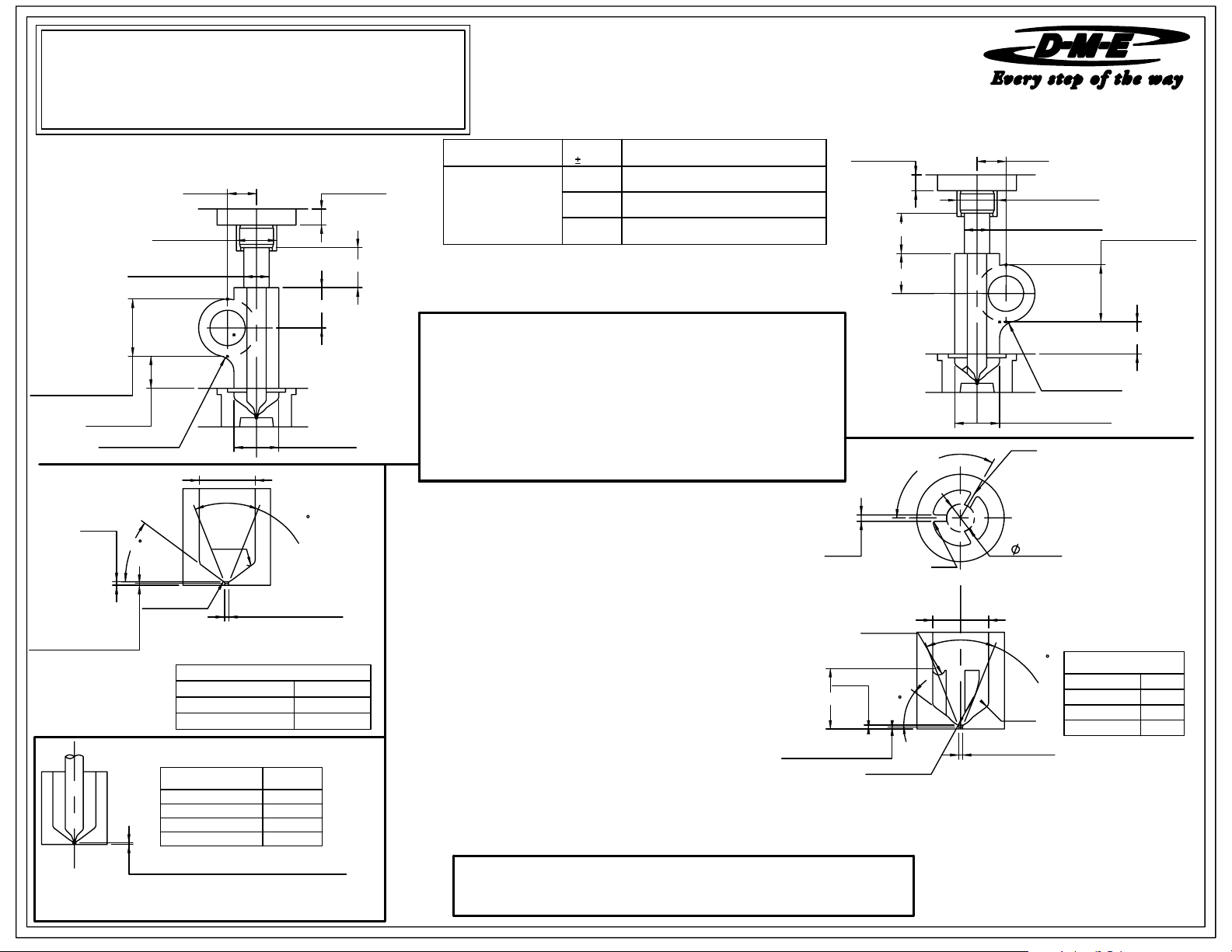
PROBE MACHINING DIMENSIONS - SOLID BLOCK DESIGN
0.625 MIN.
0.812 DIA.
8
0
C
L
.
0.812D DIA.
0.375
0.25 MIN.
0.625 MIN.
WIRING INFORMATION
Probe Heaters are supplied with 48" long leads.
Heaters are 240 VAC.
2 power leads are Multi Color.
Thermocouple is "J" Type.
Thermocouple is supplied with 48"/ 24 Gage leads.
1 T/C lead is WHITE and negative (-)
constantan (non-magnetic).
1 T/C lead is BLACK and positive (+)
iron (magnetic).
A
0.630 DIA.
+0.001
0.395
0.875/1.125 DIA.
DISTRIBUTOR
BORE
(SOLID BLOCK)
0.50 MIN.
0.25 RAD.
0.03
45
0.005 MAX. LAND
X DIMENSION (PROBE TIP SETTING
NOTE: X Dimension is for initial probe set up and may require
further adjustment. Final position of probe tip will be
determined by gate cosmetics and flow requirements.
DIA.
0.000
D DIA.
I
N
R
SPH.R.
GATE MACHINING DIMENSIONS
(SOLID BLOCK DESIGN)
AFIP3 SERIES PROBE
SPH. R. 0.187
INITIAL PROBE SET-UP DIMENSIONS
PROBE
CATALOG NUMBER
AFIP3-310-90
AFIP3-360-90 0.000-0.004
AFIP3-410-90 0.000-0.004
AFIP3-460-90
AT ROOM TEMPERATURE)
0.030/0.125
R
X DIM.
0.000-0.003
0.000-0.005
PROBE
CATALOG NUMBER
AFIP3
SERIES
NOTE: THE S SYMBOL INDICATES THE SPLIT
LINE FOR SPLIT PLATE DESIGNS.
INSTALLATION CHECK LIST
1) Insure that 0.630 diameter counterbore has been machined for probe head.
2) Check the hold down plate thickness and machined channel to
insure contact with probe and fit against adjustment ring.
3) Measure all probe machining dimensions the 0.395 diameter probe bore
must be with in the tolerance specified.
4) Double check that the probe "X" dimension is correct.
D-M-E SHALL NOT BE LIABLE FOR MISUSE OR FAILURE TO FOLLOW THE ENCLOSED
INSTRUCTIONS AND SPECIFICATIONS. D-M-E HERBY TO DISCLAIMS ALL IMPLIED
WARRANTIES, INCLUDING MERCHANTABILITY AND FITNESS FOR A PARTICULAR
PURPOSE. IN NO EVENT SHALL D-M-E BE RESPONSIBLE FOR LOSS OF USE, REVENUE
OR PROFIT, OR FOR INCIDENTAL OR CONSEQUENTIAL DAMAGED.
A DIMN.
0.010
0.428
0.544
0.550
L
USED WITH
0.394 DIA. DISTRIBUTOR PROBE
(0.875 DIA. CHANNEL OR BORE)
0.625 DIA. DISTRIBUTOR PROBE
(1.125 DIA. CHANNEL OR BORE)
0.628 DIA. DISTRIBUTOR TUBE
(1.125 DIA. CHANNEL OR BORE)
0.005 MAX. LAND
0.06 T DIA.
0.03
0.378
PROBE MACHINING DIMENSIONS - SPLIT PLATE DESIGN
0.25 MIN.
0.625 MIN.
0.625 MIN.
S
L
0.06 R
R0.06
SPH.R.
120.00°
D DIA.
5
4
0.030 / 0.125
REFER TO MINI PRINT 1700
FOR GUIDELINES OTHER THAN THOSE SHOWN
A
0.630 DIA.
+0.001
0.395
IMPORTANT: When using a single
Locator, the primary locator must
be positioned directly opposite the
distributor channel feeding the drop.
GATE MACHINING DIMENSIONS
I
N
R
DIA.
0.000
0.25 RAD.
0.812 DIA.
OPTIONAL LOCATIONS
(SPLIT PLATE DESIGN)
8
0
C
L
.
0.875/1.125
DISTRIBUTOR
CHANNEL
(SPLIT PLATE)
0.812 MIN.
AFIP3 SERIES
PROBE
D DIA.
T DIA. 0.313
SPH. R. 0.187
R0.375
0.812
D-M-E COMPANY
29111 STEPHENSON HIGHWAY
MADISON HEIGHTS
MICHIGAN 48071 USA
US 800-656-6656
CANADA 800-387-6600
www.dme.net
 Loading...