

Page 1
ME-0725-PS-217-B ID/AFN 09-08
AUTO-FIXED FINLESS PROBE
Please read carefully before installing probe
REFER TO MINI-PRINTS 1300, 1400 & 1500
D-M-E
INSTALLATION DATA
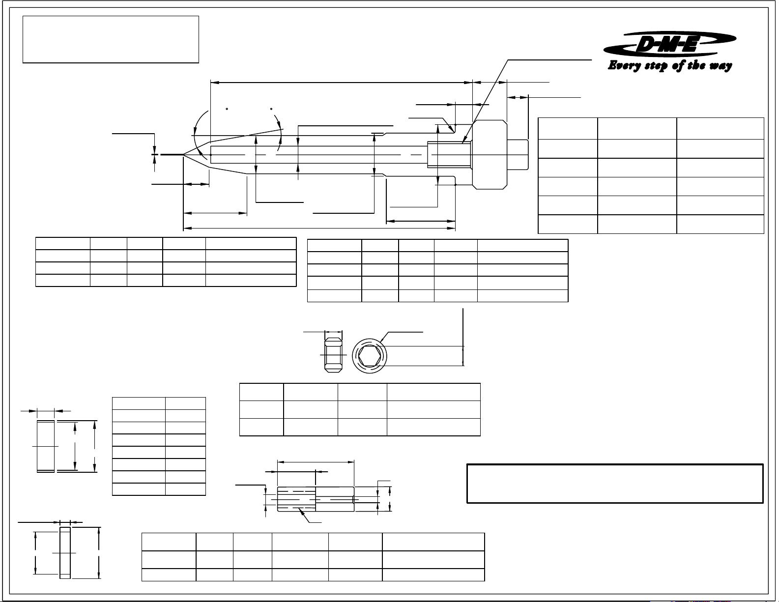
AUTO-FIXED FINLESS PROBE(CAT. NOS. AFPN.310, .410, .510 and .610)
Material: AISI D-2 Steel or equivalent (CAT. NOS. AFPN.720, .820, .920 and .1020)
Hardness: 50-55 Rc
3/8-24 TAP 0.59 DEEP
(1/2-20 TAP 0.69 DEEP)
IMPORTANT:
PARENTHESES APPLY TO LONGER
PROBES AFPN-720 THRU 1020 ONLY.
TOLERANCES SHOWN ALSO APPLY.
TO DIMENSIONS IN PARENTHESES
EXAMPLE:
+0.000
----FOR ALL PROBES
-0.001
0.625 DIA ----FOR AFPN 310 THRU 610
(0.750)DIA ----FOR AFPN 720 THRU 1020
DIMENSIONS SHOWN IN
0.014 DIA
0.370
(0.420)
25°
(30
0.920
(0.770)
)
T/C HEATER NO.C DIMB DIMA DIMCAT.NO.
AFPN-410
AFPN-510 4.625 0.875
AFPN-610
'OMIT' "T" From T/C Heater Number When Ordering Non-T/C Heaters
3.625 0.875 3.470
5.609
0.875
5.450 AFTC-216-2
AFTC-214-2
AFTC-215-24.470
10.00°
(15
)
0.556 DIA
(0.687 DIA)
C
0.250
(0.375)
0.250 DIA HEATER REF.
(0.375)
0.000
0.625 -0.001
(0.750 DIA)
A
DIA
CAT.NO. A DIM
0.03R
0.875 DIA
(0.990 DIA)
B
B DIM C DIM
AFPN-720 7.000 1.500 6.925
AFPN-820
AFPN-920
9.000
AFPN-1020
HOLD DOWN N UTS (Packaged w ith all Probes)
0.50
1.500
1.50010.000
THREAD
8.925
9.925
0.500 REF.
T/C HEATER NO.
AFTC-327-2
AFTC-328-27.9251.5008.000
AFTC-329-2
AFTC-3210-2
HEX FLAT
0.310 REF.
ITEM
HOLD DOWN
NUT
STOP
SLEEVE
REGISTER
RING
GATE
INSERT
ADJUSTEMENT
RING
USED WITH
AFPN-310 THRU-610
AFN-100
AFRR-10N
RAF-002 THRU
RAF-125
USED WITH
AFPN-720 THRU-1020
AFRR-20N
NOTE: Dimensions are in Inches
AFN-125
AFSS-12AFSS-38
AFGI-20NAFGI-10N
TO SUIT
.
ADJUSTMENT RINGS
T
0.690 DIA
FOR AFPN- 720 Thru 1020
(MOLD
MAKER
TO SUIT)
For AFP(N)-310 Thru 610
CAT. NO. TDIM.
RAF-002 0.002
RAF-003
RAF-005 0.005
0.750 DIA
RAF-007 0.007
RAF-032 0.032
RAF-062 0.062
RAF-125 0.125
CAT. NO.
0.990 DIA.0.820 DIA.
AFSS-38 0.187 0.375
AFSS-12 0.300 0.500 0.390 DIA. 1/2" - 20 AFPN-720 thru 1020
0.003
USED WITHHEX FLATTHREADCAT NO.
AFP(N)-310 thru 6109/161" - 8AFN-100
1 1/4" - 12AFN-125
STOP SLEEVES (Packaged wit h all Probes)
C'BORE
D
E C'BORE THREAD USED WITH
1.375
0.630
THREAD
AFPN-720 thru 10205/8
D-M-E SHALL NOT BE LIABLE FOR MISUSE OR FAILURE TO FOLLOW THE ENCLOSED
D
E
INSTRUCTIONS AND SPECIFICATIONS. D-M-E HERBY TO DISCLAIMS ALL IMPLIED
WARRANTIES, INCLUDING MERCHANTABILITY AND FITNESS FOR A PARTICULAR
PURPOSE. IN NO EVENT SHALL D-M-E BE RESPONSIBLE FOR LOSS OF USE, REVENUE
OR PROFIT, OR FOR INCIDENTAL OR CONSEQUENTIAL DAMAGED.
0.265 DIA. 3/8" - 24 AFP(N)-310 thru 610
Page 2
ME-0725-PS-217-B ID/AFN 08-09
AUTO-FIXED FINLESS PROBE
Please read carefully before installing probe
REFER TO MINI-PRINTS 1300, 1400 & 1500
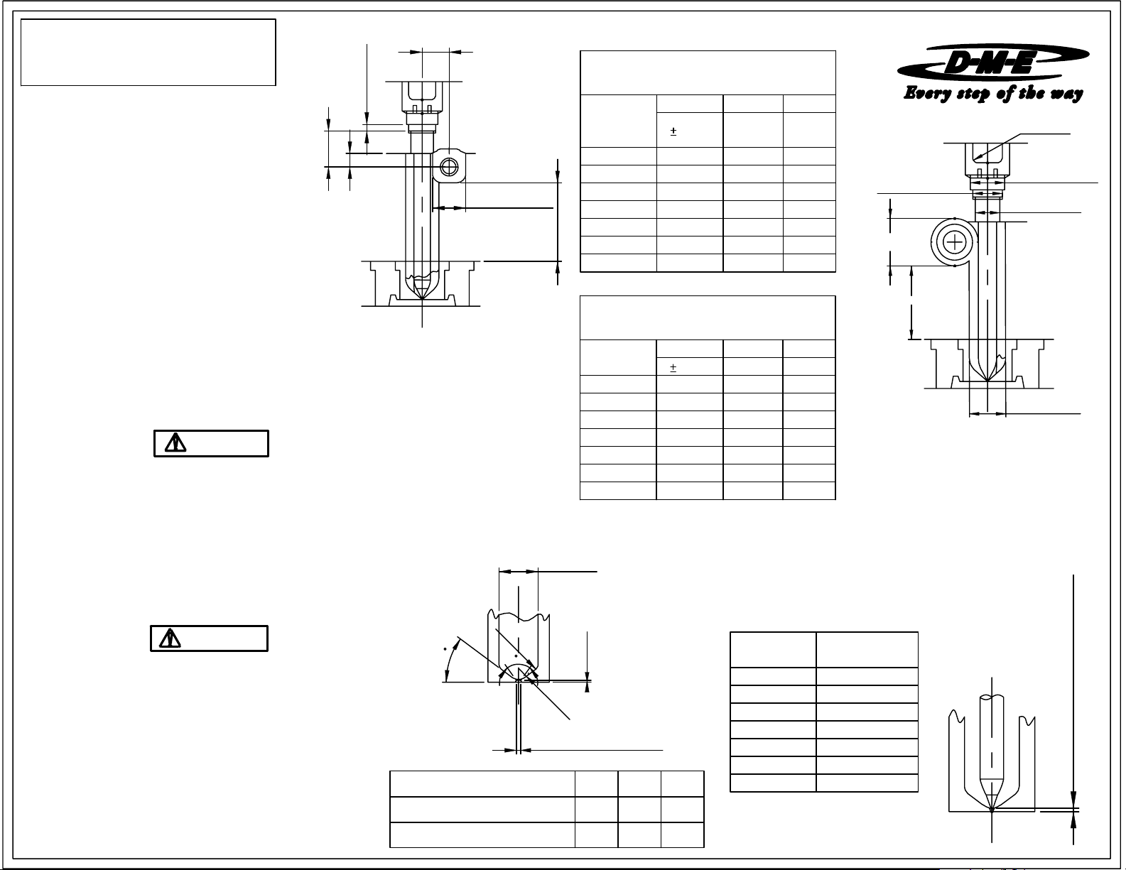
INSTALLATION CHECKLIST
1) 0.875 (1.000) Diameter Counterbore
Is the thread depth sufficient to permit full tightening
of the probe against the flat surface of the counterbore
or adjustment ring?
2) 0.626 (0.751) Diameter Probe Bore
Is the "A" dimension within the specified range?
3) Probe Set-Up Dimensions
"Refer to chart. Check "X" dimension.
D-M-E
INSTALLATION DATA
PROBE MACHINING DIMENSIONS (NOTE: Dimensions shown are common to either round or trapezoid)
±0.005
0.230
C
B
WIRING INFORMATION
Probe Heaters are supplied with 46'' long leads.
Heaters are 240 VAC.
2 power leads are MultiColor.
Thermocouple is "J" Type.
Thermocouple is supplied with 46" long leads.
1 T/C lead is WHITE and negative (-)
constantan (non-magnetic).
1 T/C lead is BLACK and positive (+)
iron (magnetic).
IMPORTANT SAFETY INFORMATION
A hot-runner system includes electrical elements and may contain molten
plastic at elevated temperature and pressure. To avoid injury, exercise
caution by reading these instructions before servicing or operating the
system.
These instructions must be passed on to the end user where they should
be read before using this product. Failure to do so can result in serious
injury or death.
NOTE: ONLY AFPN Series probes are
recommended for the trapezoidal and
round split plate concept
DANGER
Failure to comply will result in serious injury or death:
ELECTRICAL HAZARDS
Improper voltages or grounding can result in electrical shock. Use only
with proper voltage and a proper earth ground.
To avoid electrical shock, do not operate product when wet.
Do not operate this equipment with covers or panels removed.
To avoid electrical shock, turn off main power disconnect and lockout /
tag out before servicing this device. Do not connect temperature sensors to
electrical power. It will damage the product and it can cause fire, severe
injuries or even death.
If green ground wire present wire must be connected to the ground.
Do not rebend rigid leads. Rebending leads might result in damage to circuit.
Product might absorb moisture when cool. Use low Voltage or power to drive
out residual moisture before applying full power. Failure to do so may cause
damage to this product.
WARNING
Failure to comply can result in serious injury or death:
STORED ENERGY AND HIGH TEMPERATURE HAZARDS
This product maintains molten plastic at high pressure. Use caution when
operating and servicing the system.
Physical contact with molten plastic may result in severe burns. Proper
protective equipment, including eye protection, must be worn. This product
has heated surfaces. Use caution when operating and servicing the system
to avoid severe burns. Proper protective equipment should be worn.
D-M-E COMPANY
29111 STEPHENSON HIGHWAY
MADISON HEIGHTS
MICHIGAN 48071 USA
US 800-656-6656
CANADA 800-387-6600
www.dme.net
A
DISTRIBUTOR TUBE (1.25 CHANNEL)
(0.355)
ADJUSTMENT RING
PROBE
CAT. NO.
SL
AFPN-410 0.796 0.37 1.25
AFPN-510 0.796 0.37 1.25
1.250/2.000
DIST CHANNEL
AFPN-610 0.796
AFPN-720 0.861 0.46 1.96
AFPN-820 0.861
AFPN-920
1.00 MIN
AFPN-1020
DISTRIBUTOR TUBE (2.00 CHANNEL)
PROBE
CAT. NO.
AFPN-410 1.171 0.48 1.35
AFPN-510 1.171 0.48 1.35
AFPN-610 1.171 0.48 1.35
AFPN-720 1.236
AFPN-820 1.236 0.62 2.12
AFPN-920 1.236
D DIA
R
5
4
Y
PROBE CAT NO.
AFPN - 310 THRU - 610
0.030
Y°=80° INCL. MIN
S
P
H
GATE DIA. (.040 MIN.)
TO SUIT APPLICATION
90° INCL. MAX
.
R.
D
DIA.
1.000
AFPN - 720 THRU - 1020 1.125 0.250 0.50
USED WITH 0.875 DIA.
A DIM.
0.020
B DIM. * C DIM
MIN. MIN.
0.37
0.46 1.96
0.861 0.46
USED WITH 1.625 DIA.
A DIM. B DIM. C DIM
0.020 MIN. MIN.
0.62
0.62
0.621.236AFPN-1020
NOTE: Dimensions are in Inches
INITIAL PROBE SET-UP DIMENSIONS
PROBE
CAT. NO.
AFPN-410
AFPN-610 0.000 - 0.006
AFPN-720 0.000 - 0.007
AFPN-820 0.000 - 0.008
AFPN-920 0.000 - 0.009
SPH.
R
0.187
R
0.380
AFPN-1020 0.000 - 0.010
1.25
1.960.460.861
1.96
2.12
2.12
2.12
.
0.000 - 0.004
0.000 - 0.005AFPN-510
0.125 R.
MIN.
1"-8 TAP
0.875
±0.002
(1.000 DIA)
1.250/2.000 DIA
DIST. CHANNEL
1.00 MIN
Dimensions in parentheses apply to AFPN-720 thru 1020 only
* The purpose of the "B" dimension is to
insure adequate probe bore depth.It is
NOT used to establish the location of
the distributor tube.
(1 1/4"-12 TAP)
+0.001
0.626
0.000
(0.751 DIA)
1.000 DIA
(1.125 DIA)
X DIM.
X DIMENSION
(PROBE TIP SETTING
AT ROOM TEMPERATURE)
 Loading...