

Page 1

Analog Resistive Touch Screen Controller
TSC-34/U-L User’s Guide
Page 2

TSC-34/U-L User’s Guide
Table of Contents
1. Product Overview ................................................................................................................ 2
1-1. Products Applicable ...................................................................................................................... 2
1-2. Overview ...................................................................................................................................... 2
1-3. Peripheral Composition Overview.................................................................................................. 3
2. Specifications ...................................................................................................................... 4
3. Connector ............................................................................................................................ 5
3-1. Explanation of a connector terminal ............................................................................................... 5
3-2. The mounted connector ................................................................................................................ 5
4. Packing Specification ......................................................................................................... 6
4-1. Outline ......................................................................................................................................... 6
4-2. Packing material ........................................................................................................................... 6
4-3. Outer case and lot label ................................................................................................................ 6
4-4. Product name label ....................................................................................................................... 7
5. Changes & Improvements .................................................................................................. 8
5-1. Version History ............................................................................................................................. 8
6. Warranty .............................................................................................................................. 9
6-1. Warranty Period ........................................................................................................................... 9
6-2. Warranty Target ........................................................................................................................... 9
6-3. Warranty Exceptions ..................................................................................................................... 9
7. Precautions for Use .......................................................................................................... 10
7-1. General Handling........................................................................................................................ 10
7-2. Others ........................................................................................................................................ 10
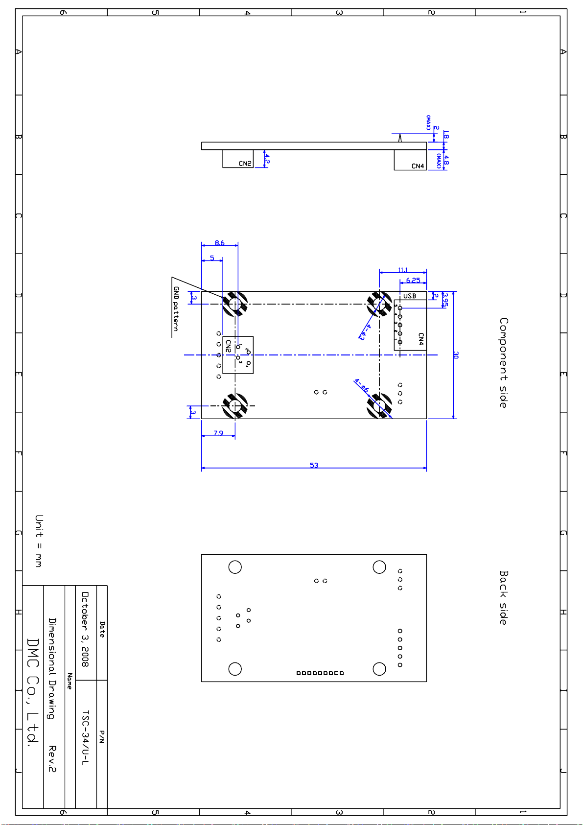
Dimensional Drawing
Document No. DER-S0102A 1 Rev.1.2 ©2012 DMC Co., Ltd.
Page 3
TSC-34/U-L User’s Guide
1. Product Overview
1-1. Products Applicable
This specification is applicable to TSC-34/U-L.
1-2. Overview
TSC-34/U-L is a touch screen controller board that performs an A/D conversion of an analog signal of a 4
wire resistive touch screen, and transmits the coordinate data to the host in a 10-bit resolution via USB
interface. TSC-34/U-L can be used for various applications for its functions including the power saving
mode, seven sampling speed settings (max. 150p/s *1), two external switch connections, and automatic
calibration data loading with an external EEPROM.
TSC-34/U-L is a succeeding model of the boards of the TSC-10/USB-PI. TSC-34/U-L is lead-free and
compliant with RoHS.
§ TSC-34/U-L TSC-34/U-L dispenses a need to newly design the peripheral circuits, and can easily
be used by connecting to the touch screen and the host. Using the driver software *2
enables the mouse emulation on various operation systems and dispenses the need
to newly design the controller software.
TSC-34/U-L is the product compatible with software of the TSC-10/USB-PI.
*1: 150 transmissions of coordinate data per second.
*2: Please contact the local sales representatives for software availability.
Document No. DER-S0102A 2 Rev.1.2 ©2012 DMC Co., Ltd.
Page 4
TSC-34/U-L User’s Guide
xl
A_in
Output Data
A
0V
0000h (Min.)
B
1.25V
00FFh
C
2.5V
01FFh
D
3.75V
02FFh
E
5V
03FFh (Max.)
Vcc
= 5.0V
xl
A_in
X-resistive-layer
Y-resistive-layer
Touch
Vcc
(TSC-30/IC)
E D C B A
(Touch Screen)
(TSC-34/U-L)
USB
To host
Y-resistive-layer
X-resistive-layer (reverse side)
xl
T
X electrode
(reverse side)
Y electrode
Vcc
A
A B C D E
A_in
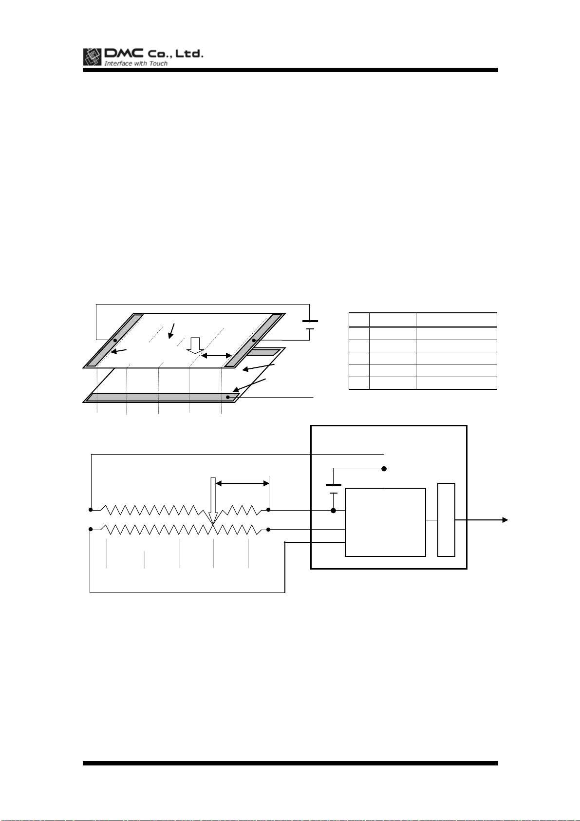
1-3. Peripheral Composition Overview
A resistive touch screen is operated by resistance sensitive system between two layers such as film or
glass. Two pieces of transparent materials with conductive coating are placed in the same direction as
two electrodes face each other. The touch screen is activated when these transparent conductive layers
are pressed to contact each other with a finger or a pen. The one of these conductive layers functions as
an X-coordinates electric circuits and the other as a Y-coordinates circuits. To measure the
X-coordinates TSC-34/U-L supplies voltage, Vcc to the one of X-coordinates electrodes with GND to the
other. When the touch screen is pressed under this environment the voltage of the X-coordinates resistance is detected by the Y-coordinates electrode (A_in) at the input point (x1), where the X-Y coordinate
resistance layers make contact. The detected voltage in supply side is higher than the GND side, which
means ‘A_in’=Vcc at the point ‘E’ and ‘A_in’=0(*1) at the point ‘A’. TSC-34/U-L calculates coordinates
data starting from A/D conversion of the ‘A_in’ voltage. The Y-coordinates is measured in the same way.
By repeating this process alternately, coordinate value at the input point is determined.
(*1) Excluding the loss in the controller circuits and touch screen. Actual detected voltage should be lower than ‘Vcc - GND’ because of loss happened in the circuitry.
Document No. DER-S0102A 3 Rev.1.2 ©2012 DMC Co., Ltd.
Page 5
TSC-34/U-L User’s Guide
Item
Rating
Remarks
Operating Temp.
0°C to +70°C
No dew condensation
Storing Temp.
-20°C to +85°C
No dew condensation
Supply Voltage
DC 4.0V to 5.25V
Consumption Current
25mA
150p/s, Vin=Vbus,
Touch screen is activated.
Correspondence
(USB)
Spec
USB Specification 2.0 Full Speed
Transfer Mode
Control transfer (command)
Interrupt transfer (coordinate)
Device class
Vendor definition
Frequency
6MHz
6MHz fixed
Dimension
30 x 53 mm
Max height of components
4.8 mm
Description
Rating
Note
Coordinate Output Rate (point/sec)
(1) point mode
(2) 30p/s (3) 50p/s
(4) 80p/s (5) 100p/s
(6) 130p/s (7) 150p/s
Default: 150pps with DMC original
driver software.
Coordinate Resolution
10bit (1024 x 1024)
The value will be lower in the active
area of the touch screen
Linearity Error
3 LSB
Input Response Time
10ms (TYP)
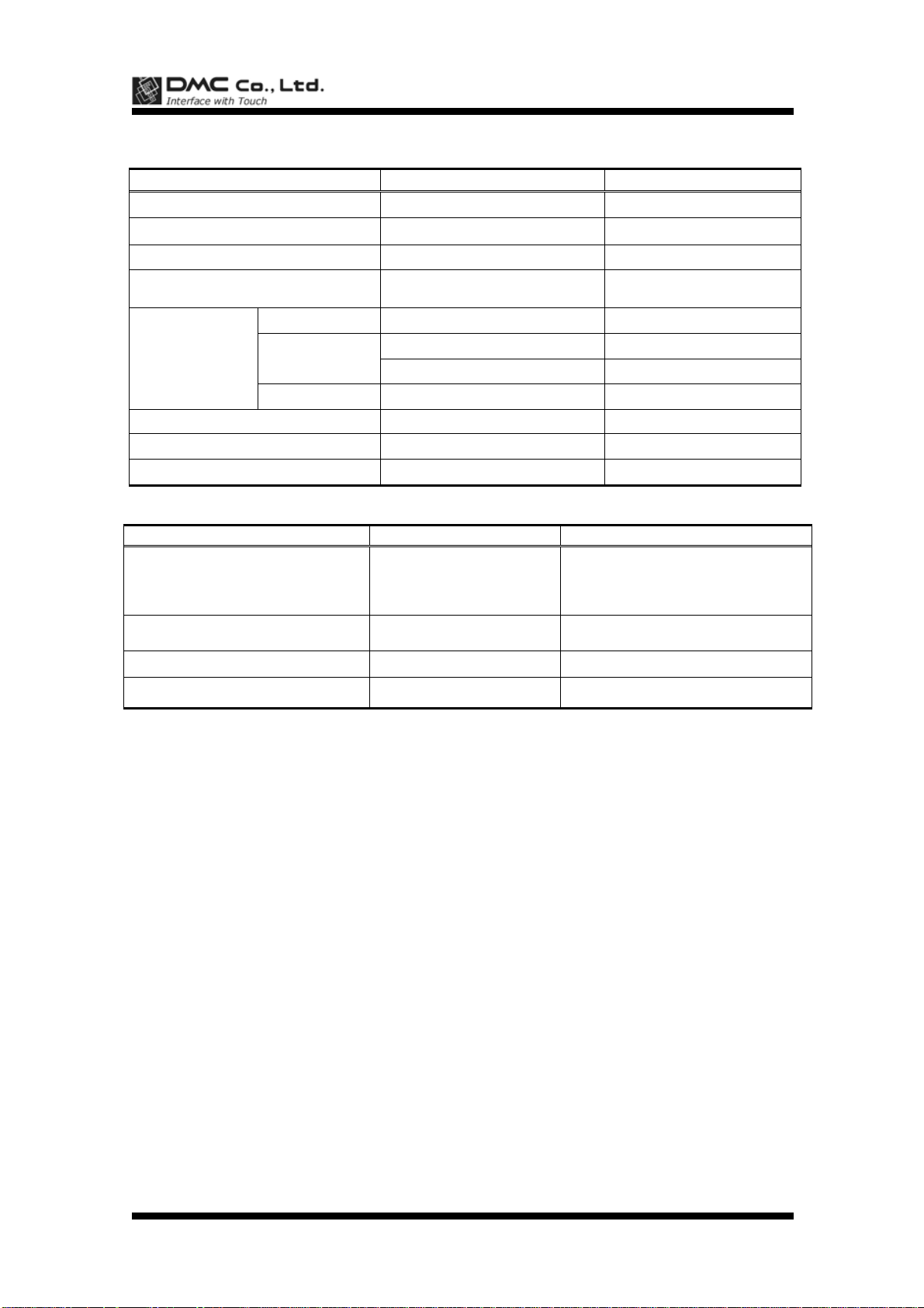
2. Specifications
General Specifications
Performance Specifications
Document No. DER-S0102A 4 Rev.1.2 ©2012 DMC Co., Ltd.
Page 6
TSC-34/U-L User’s Guide
CN
Terminal
Name
Function
CN2
1
XL
Touch screen Input XL.
2
YU
Touch screen Input YU.
3
XR
Touch screen Input XR.
4
YD
Touch screen Input YD.
CN4
1
Vbus
USB Vbus
2
D-
USB D-
3
D+
USB D+
4
GND
USB GND
5
Shield
USB FG
CN
P/N
Manufacturer
CN2
00-8370-049-000-800+
Kyosera Elco Corporation
CN4
S5B-PH-K-S
J.S.T. Mfg Co., Ltd
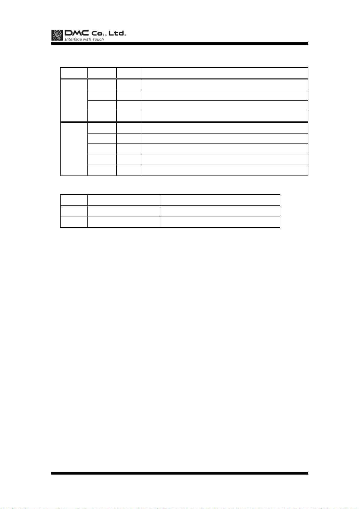
3. Connector
3-1. Explanation of a connector terminal
3-2. The mounted connector
Document No. DER-S0102A 5 Rev.1.2 ©2012 DMC Co., Ltd.
Page 7
TSC-34/U-L User’s Guide
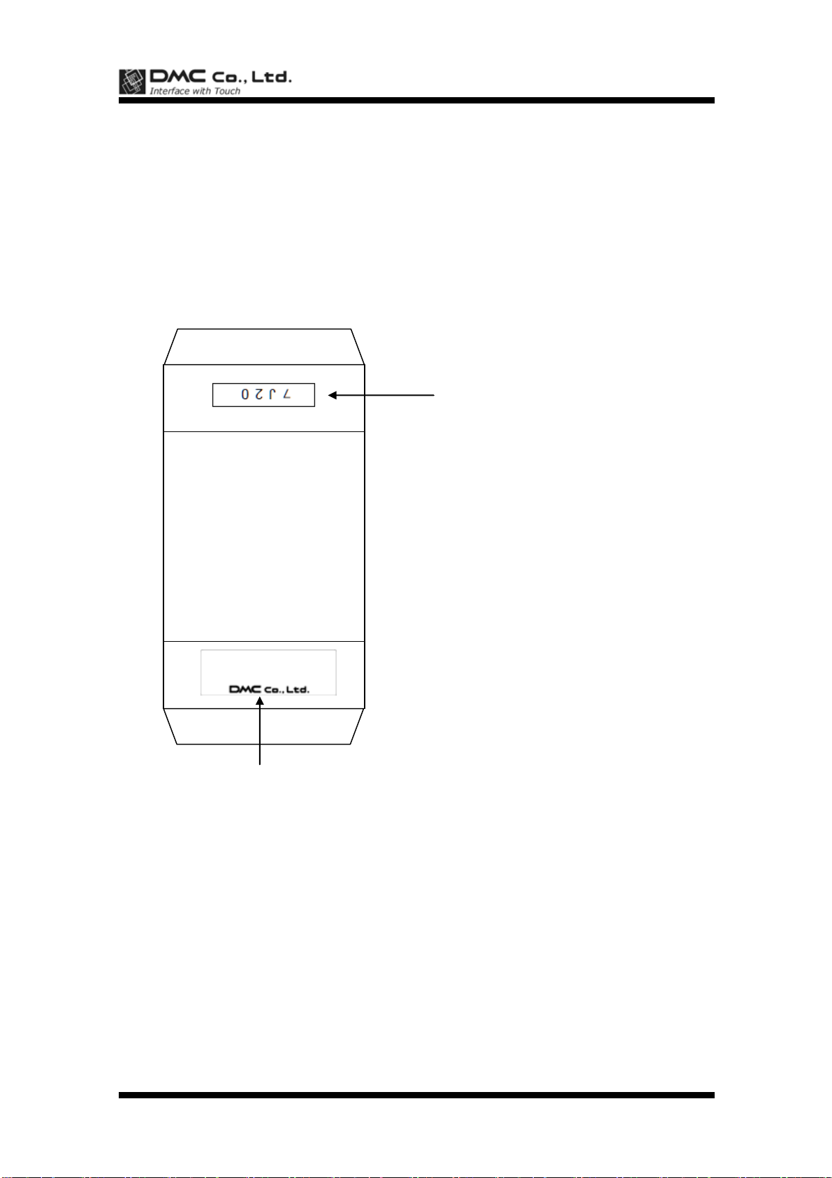
T S C - 3 4 / U - L
Lot number
Sample: 7J20
7: the last digits of the year
J: Month Jan : A Jul : G
Feb : B Aug : H
Mar : C Sep : I
Apr : D Oct : J
May : E Nov : K
Jun : F Dec : L
20: Date manufactured
Product name, DMC logo
4. Packing Specification
4-1. Outline
TSC-34/U-L is wrapped up in the air packing of the prevention of static protection type and puts it in a
packing box.
4-2. Packing material
Outer case: 75 x 55 x 15 mm, clay coated newsback board
Cushioning: 120 x 70 mm, air packing, static protection
4-3. Outer case and lot label
Document No. DER-S0102A 6 Rev.1.2 ©2012 DMC Co., Ltd.
Page 8
TSC-34/U-L User’s Guide
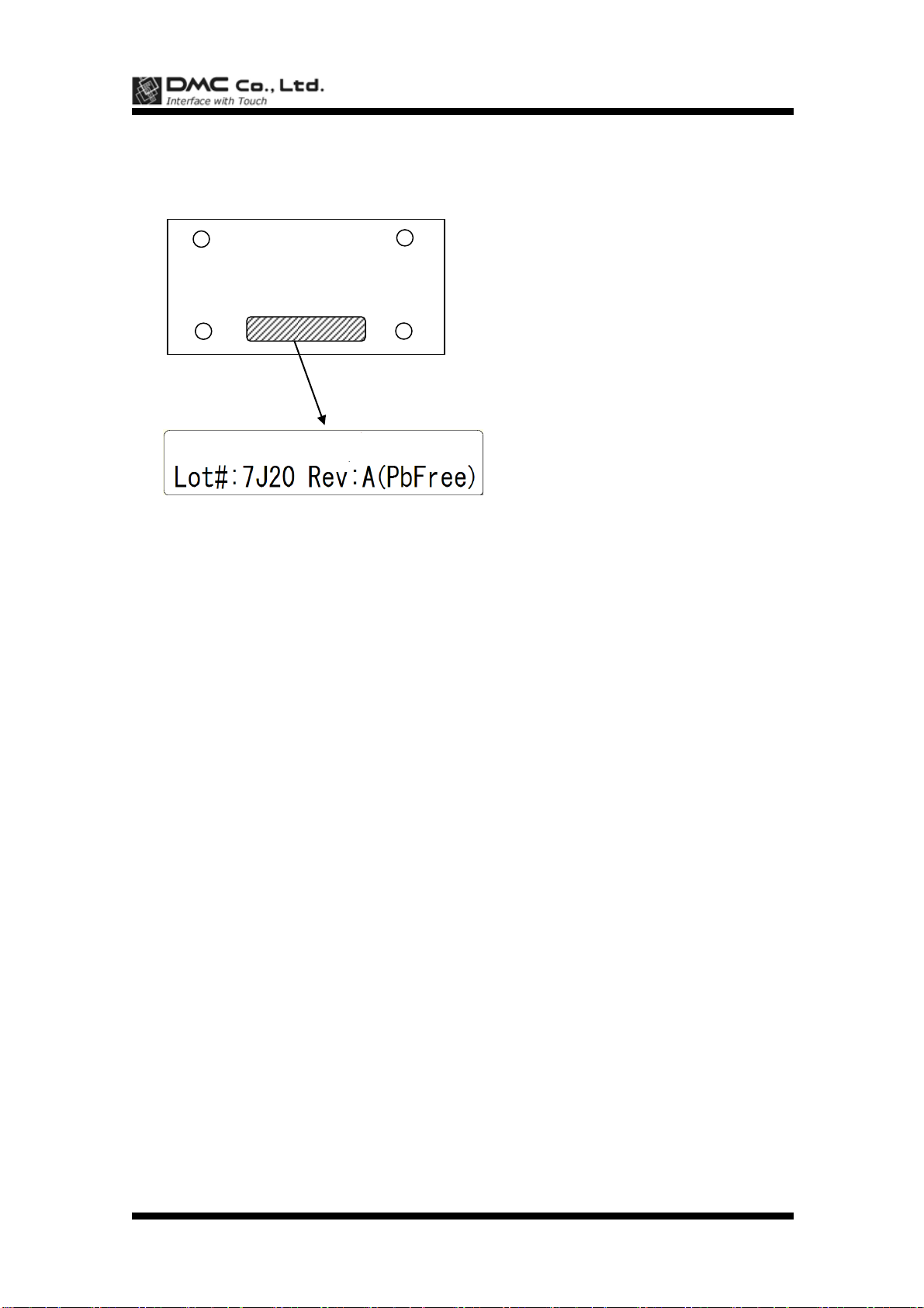
TSC-34/U-L: Product name
Lot#: 7J20
7: the last digits of the year
J: Month Jan : A Jul : G
Feb : B Aug : H
Mar : C Sep : I
Apr : D Oct : J
May : E Nov : K
Jun : F Dec : L
20: Date manufactured
Rev: Revision information
(PbFree): lead free
TSC-34/U-L
4-4. Product name label
Backside of board
Document No. DER-S0102A 7 Rev.1.2 ©2012 DMC Co., Ltd.
Page 9
TSC-34/U-L User’s Guide
5. Changes & Improvements
5-1. Version History
§ TSC-34/U-L
Ver0.1 (February 6, 2008)
Draft release
Ver 1.0 (March 13, 2008)
First release
(Change from ver0.1)
2. Specifications Consumption Current and Input Response Time were added.
Dimensional Drawing Revision 1 for first release
Ver 1.1 (October 20, 2008)
3. Connector CN6 was deleted. (Correction of typographical error)
Dimensional Drawing CN6 was deleted.
Ver 1.2 (May 25, 2012)
Address has changed as Tokyo office had moved
Document No. DER-S0102A 8 Rev.1.2 ©2012 DMC Co., Ltd.
Page 10
TSC-34/U-L User’s Guide
6. Warranty
6-1. Warranty Period
§ The warranty period is limited to 1 year from the date of shipping. The warranty for the initial defection
such as appearance defection is limited to 1 month.
§ Any defected parts under proper use will be examined by the supplier and replaced by the new parts if
the defection is considered to be caused by the supplier.
§ The replacement is subject to be included in the next lot.
6-2. Warranty Target
§ The warranty only covers the product itself and does not cover any damage to others caused by using
this product. Onsite repair or replacement is not supported.
§ We will do our best for delivery problem and product defections, but the warranty for the production line
is not covered.
6-3. Warranty Exceptions
Following conditions are not covered with the warranty and subject to charge.
§ Any malfunctions and damages during transportation and transfer by the user.
§ Any malfunctions and damages caused by a natural disaster or a fire.
§ Any malfunctions and damages caused by static electricity
§ Any malfunctions and damages caused by the failure of the associated equipment.
§ If the product is remodeled, disassembled or repaired by the user.
§ If the product is glued onto the equipment and uninstalled.
§ Any malfunctions and damages caused by an improper usage and handling against the specifications
and notes.
Document No. DER-S0102A 9 Rev.1.2 ©2012 DMC Co., Ltd.
Page 11
TSC-34/U-L User’s Guide
Initialization
Mode
05h S_Rate
Idle Mode
Initialization Pro-
cess Time
(Approx. 500ms)
06h(ACK)or15h(
NAK)
TSC-10 The Host
Initialization
Process
7. Precautions for Use
7-1. General Handling
§ Keep the product away from any conductive objects while in use.
§ Do not touch the conductive part of the product to avoid being damaged by the electrostatic discharge.
Follow the proper procedure for handling.
§ Keep the product in the proper storing environment and avoid any load to the product.
§ Do not use or store the product in the severe condition like following:
Wet environment or a condition where the product is likely to get wet.
Where dew condensation is likely to occur.
Near solvent or acid.
§ Do not take apart or alter the product.
7-2. Others
§ The contents of this document are subject to change without notice.
§ The manufacturer or sales representatives will not be liable for any damages or loss arising from use of
this product.
§ This product is intended for use in standard applications (computers, office automation, and other office
equipment, industrial, communications, and measurement equipment, personal and household devices,
etc.) Please avoid using this product for special applications where failure or abnormal operation may
directly affect human lives, or cause physical injury or property damage, or where extremely high levels
of reliability are required (such as aerospace systems, vehicle operating control, atomic energy controls,
medical devices for life support, etc.).
§ Any semiconductor devices have inherently a certain rate of failure. The user must protect against injury,
damage, or loss from such failures by incorporating safety design measures into the user’s facility and
equipment.
TSC-34/U-L User’s Guide
Rev. 1.2, May 25, 2012
©2012 DMC Co., Ltd.
This document can be freely distributed, but any alternation to this document is prohibited.
DMC Co., Ltd.
http://www.dmccoltd.com/english/
11F Nisseki Takanawa Bldg., 2-18-10 Takanawa, Minato-ku, Tokyo 108-0074, Japan
Phone: +81-3-6721-6731 (Japanese), 6736 (English) Fax: +81-3-6721 -6732
Document No. DER-S0102A 10 Rev.1.2 ©2012 DMC Co., Ltd.
Page 12
 Loading...