

Page 1
Analog Resistive Touch Screen Controller
TSC-30/IC product specification
Page 2

TSC-30/IC Product Specification
Table of Contents
1. Products outline ........................................................................................................... 2
1-1. Scope of Application ................................................................................................................... 2
1-2. Outline......................................................................................................................................... 2
1-3. Features ...................................................................................................................................... 2
1-4. General specification ................................................................................................................... 3
2. Pin layout and representation ........................................................................................ 4
3. Pin functions ............................................................................................................... 5
4. Initial setting ................................................................................................................ 7
4-1. EEPROM setting ......................................................................................................................... 7
4-2. Communication mode setting ...................................................................................................... 7
4-3. Touch screen mode setting ........................................................................................................ 7
4-4. Configuration in USB mode ........................................................................................................ 8
4-5. Panel ID setting (USB mode)..................................................................................................... 8
5. Data sheet .................................................................................................................. 9
5-1. Absolute maximum rating ........................................................................................................... 9
5-2. Recommended operational conditions ....................................................................................... 10
5-3. Timing requirement ................................................................................................................... 12
5-4. DC standards ............................................................................................................................ 14
6. Packaging Specification .............................................................................................. 16
6-1. Outline....................................................................................................................................... 16
6-2. Notes on storage/handling ........................................................................................................ 16
6-3. Basic packaging ........................................................................................................................ 16
6-4. Small group packaging ............................................................................................................. 17
6-5. Tray specification ...................................................................................................................... 18
6-6. Product name label specification .............................................................................................. 18
7. Storage Specification ................................................................................................. 19
7-1. Storage Conditions.................................................................................................................... 19
7-2. Baking ....................................................................................................................................... 19
8. Implementation Temperature Specification ................................................................... 20
9. Terminal Pin Specification ........................................................................................... 21
10. Cleaning ................................................................................................................. 21
11.Changes and improvements ....................................................................................... 22
11-1. Version history ........................................................................................................................ 22
12. Warranty ................................................................................................................. 24
12-1. Warranty Period ...................................................................................................................... 24
12-2. Warranty Target ...................................................................................................................... 24
12-3. Warranty Exceptions ............................................................................................................... 24
13. Notes on use ........................................................................................................... 25
13-1. Overall handling ...................................................................................................................... 25
13-2. Others ..................................................................................................................................... 25
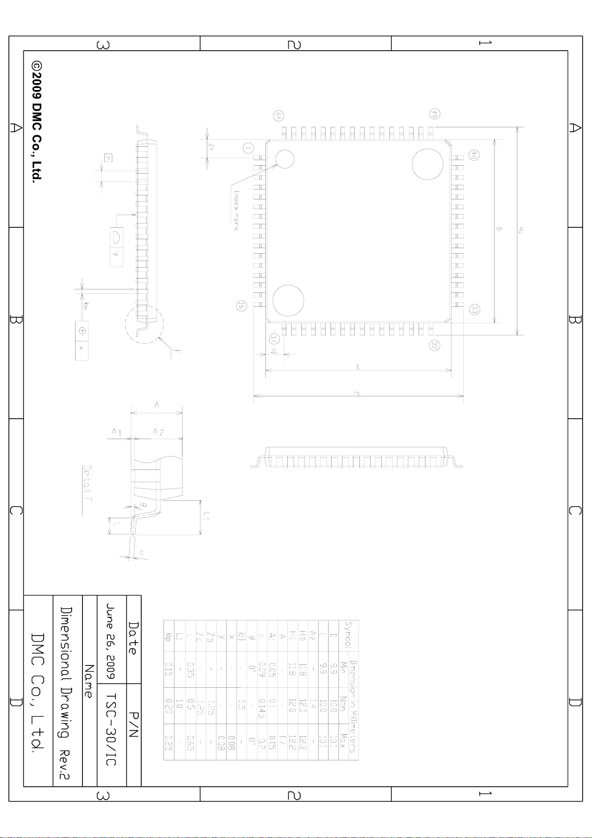
Dimensional Drawing
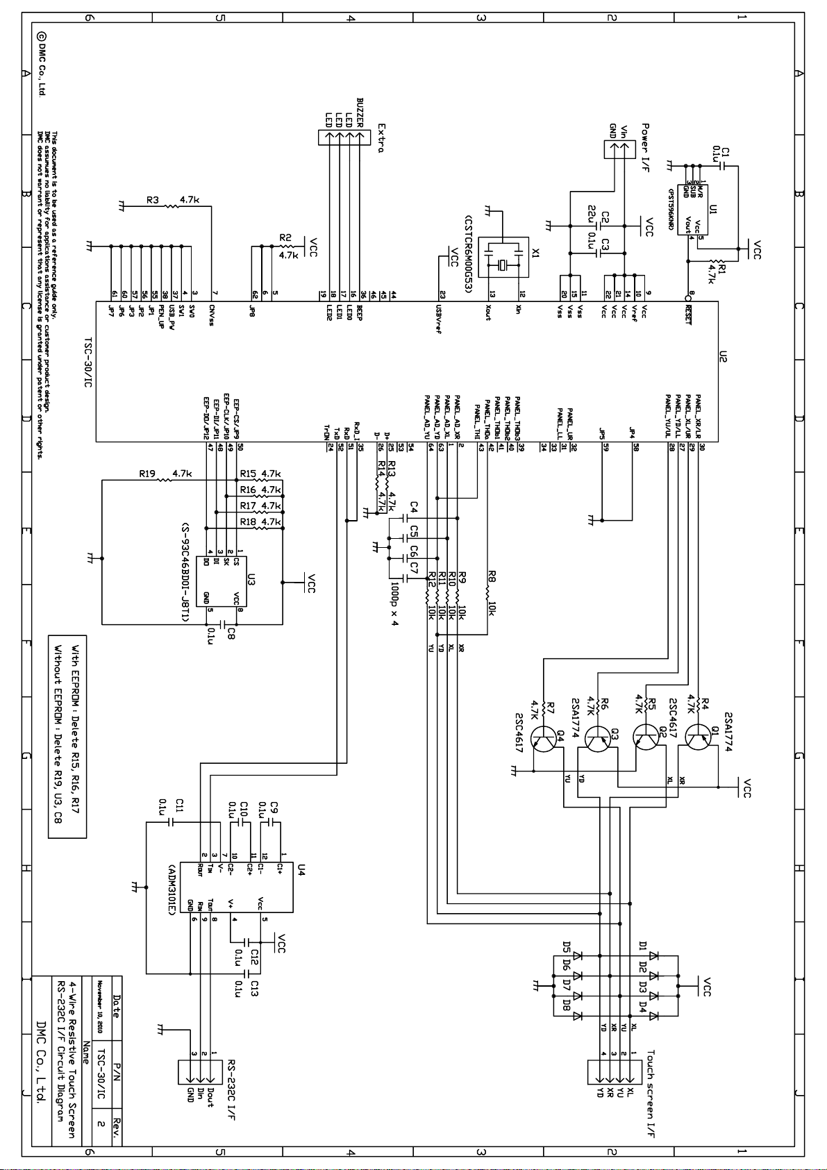
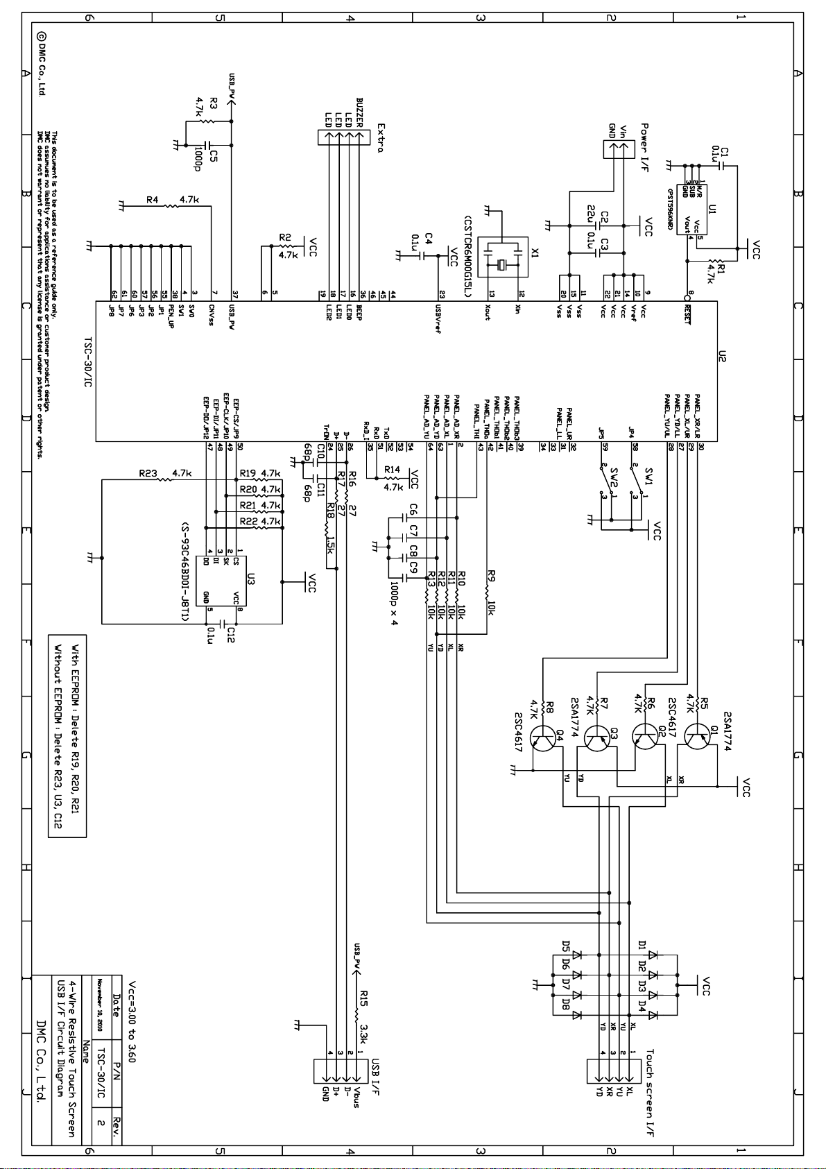
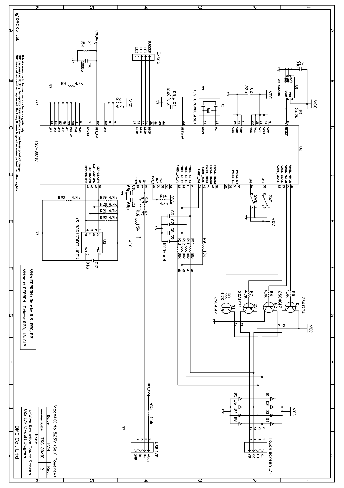
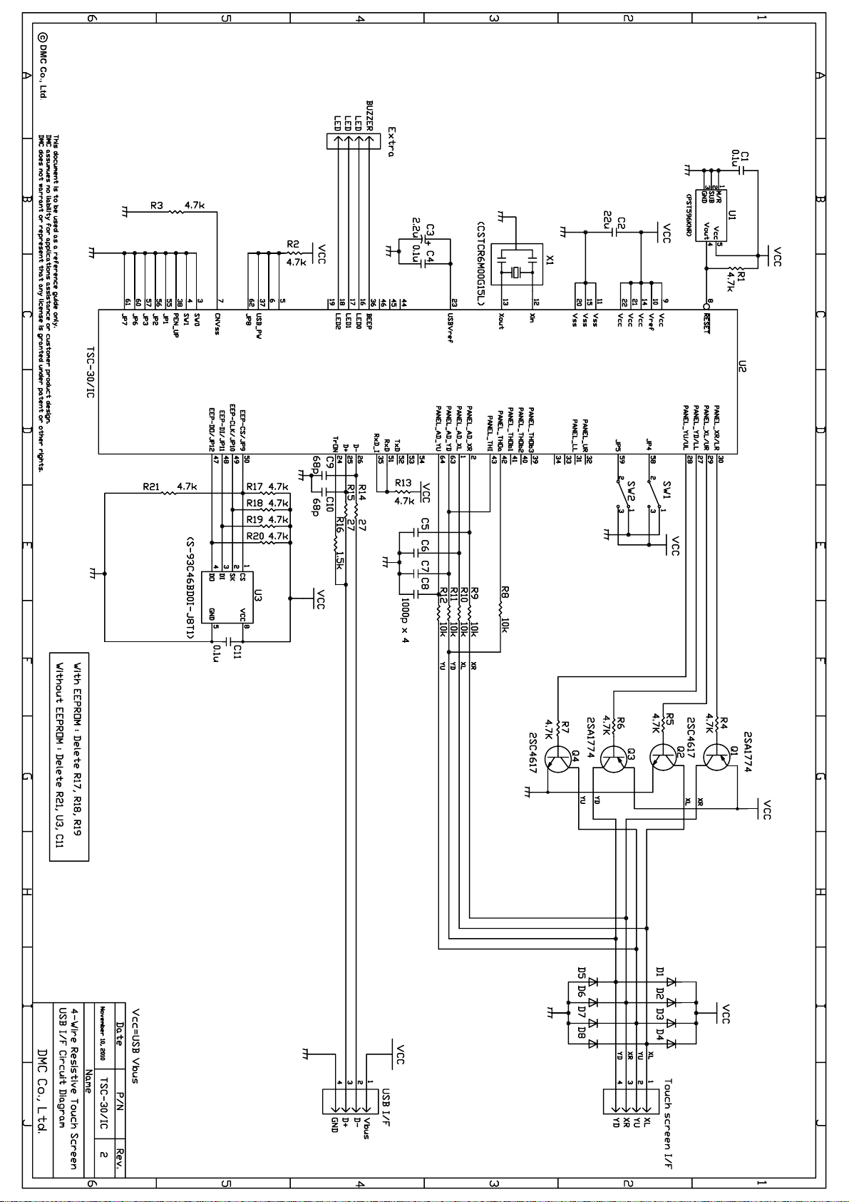
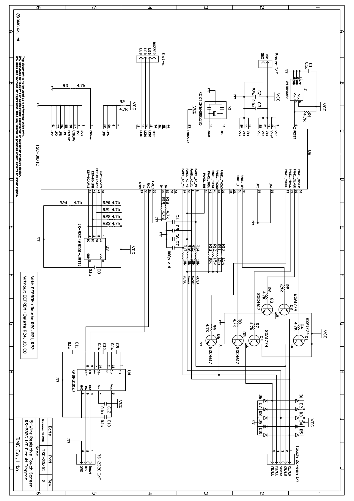
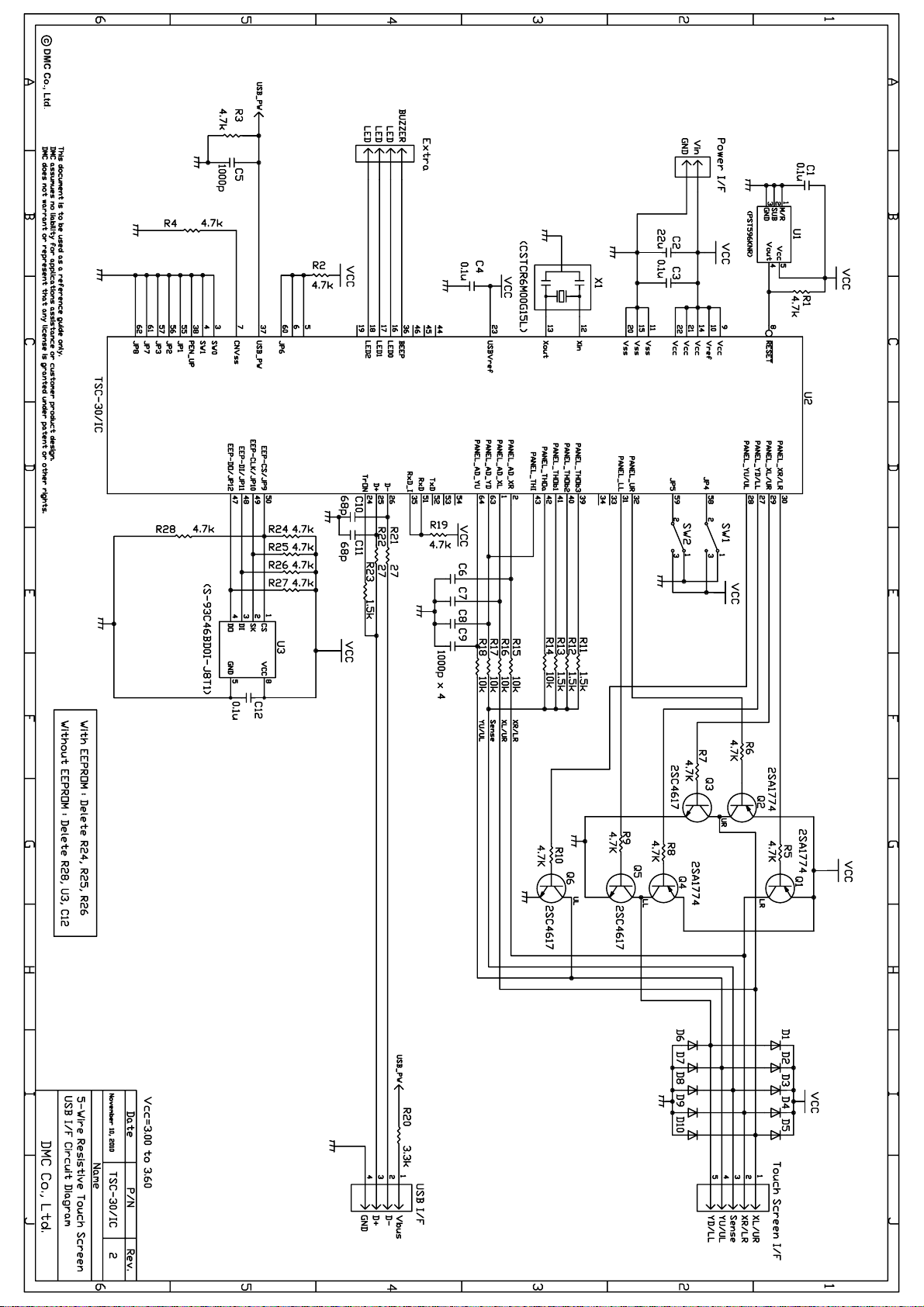
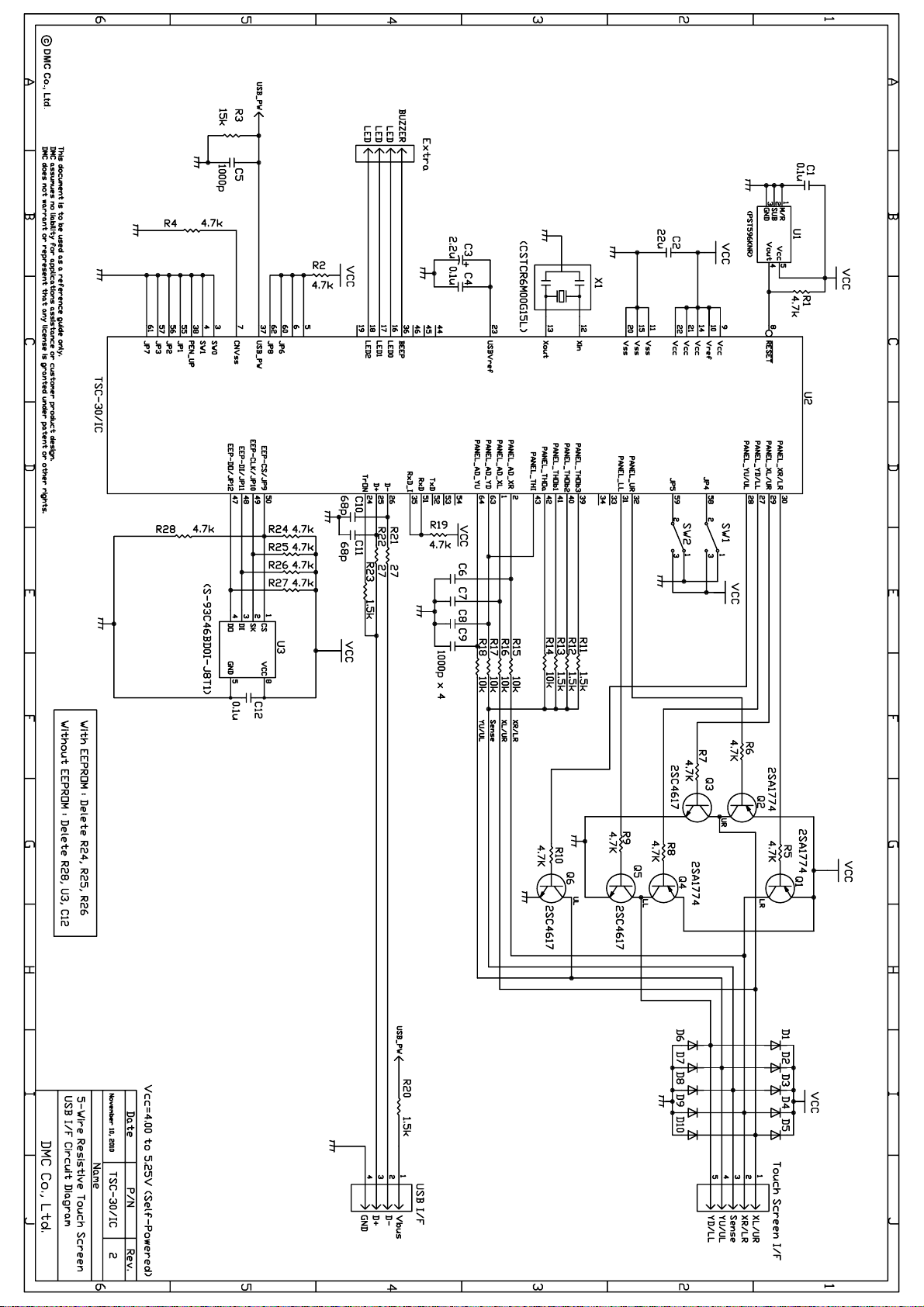
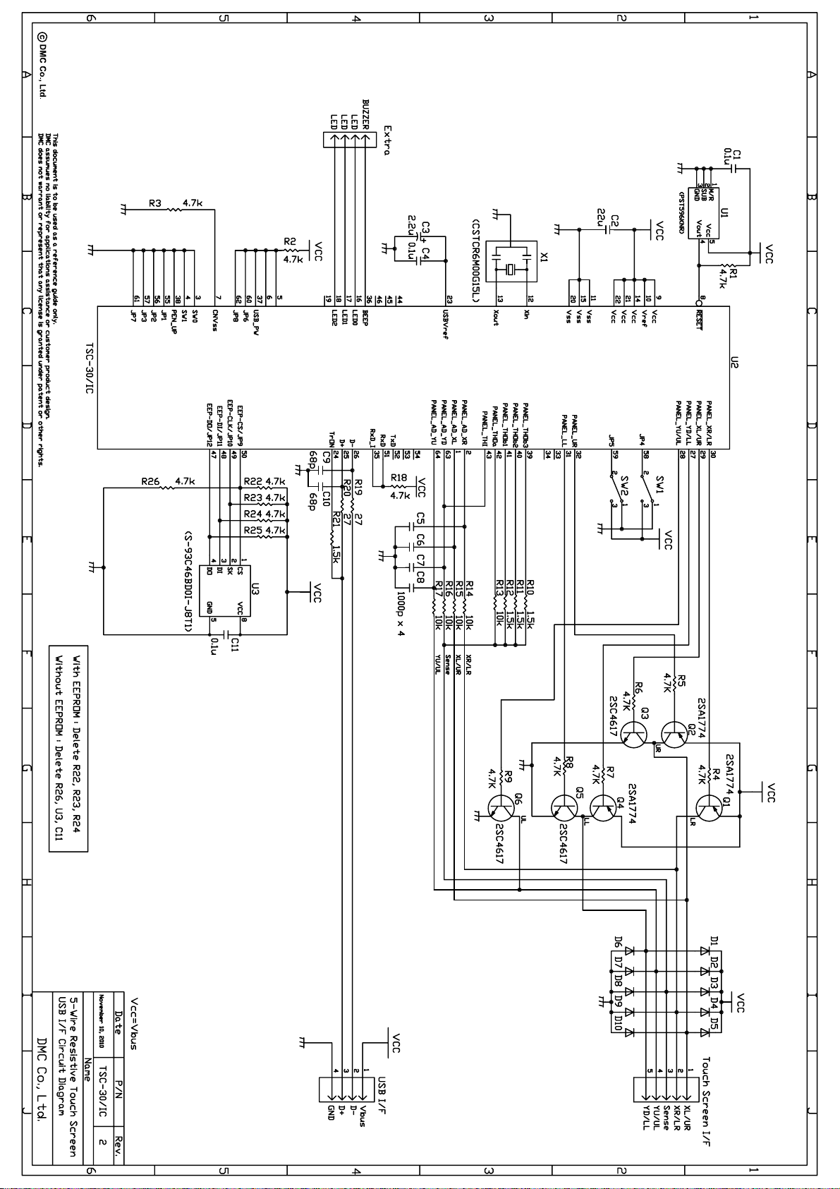
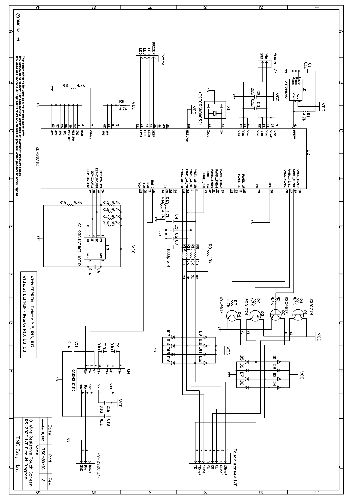
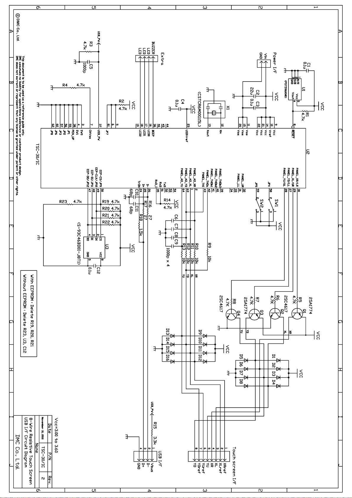
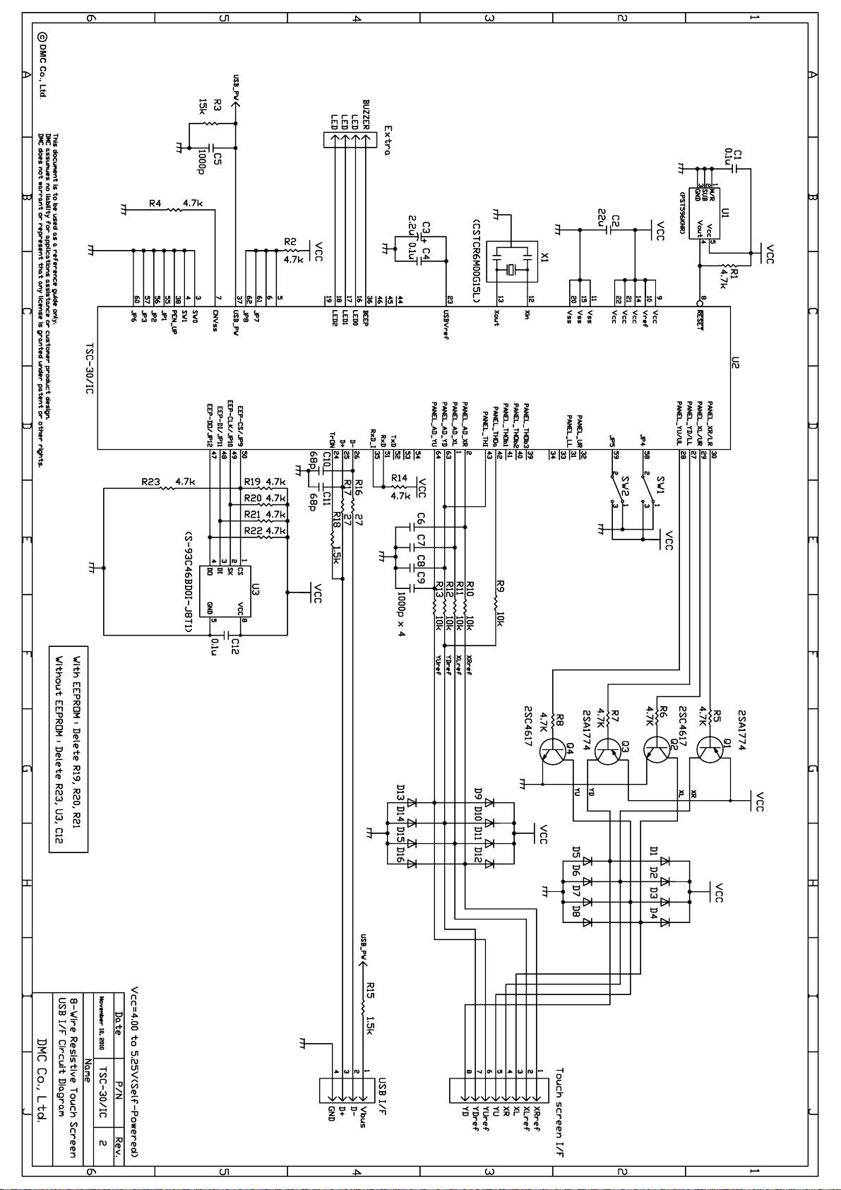
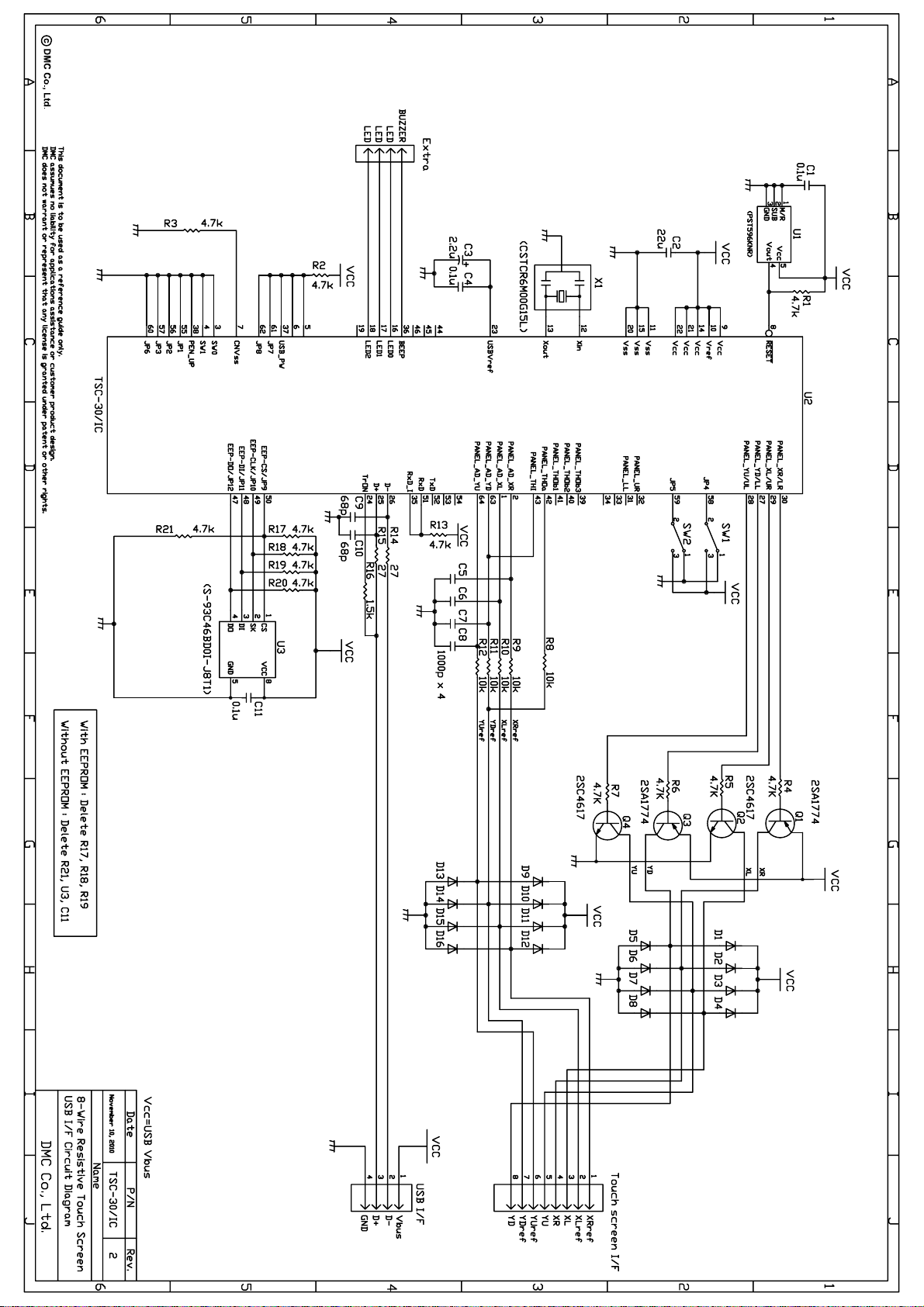
Circuit Diagram
Document No. DER-S0098A 1 Version 1.3 ©2012 DMC Co., Ltd.
Page 3

TSC-30/IC Product Specification
1. Products outline
1-1. Scope of Application
This specification applies to the TSC-30/IC.
1-2. Outline
TSC-30/IC is an analog touch screen control IC that performs A/D conversion on analog signal for the
4-wire, 5-wire and 8-wire resistive analog touch screen, and transmits coordination data with 10bit
resolution to the host in a 9600bps serial (asynchronous) and USB.
At the coordinate detection, internal filtering process provides a stabilized coordinate value. By using the
correction function, in addition to the losses that occur in the circuit, display deflection between touch
screen input point that occur in each element and indicator cursor can be corrected to adjust the display
position.
1-3. Features
§ Two coordinate output modes are provided and selected per application: “Coordinate data mode”
where coordinate information is sent with 10bit resolution as it is, and “correction data mode” where
read coordinate is converted to the indicator’s display coordinate and sent.
§ “Correction data mode“ is available after EEPROM is externally attached. It enables to set up to nine
correction points. Coordinate data can be corrected with the base of correction points. Using this
function allows the host driver to make the implementation of correction function unnecessary. In
addition, by placing correction points at the touch screen center and center points of four edges of
touch screen, resistance value deviation of transparent electrode film can be corrected.
§ USB has multi-touch screen function enable two simultaneous connections to the host.
§ Two external switch functions are always available in the coordinate (correction) data mode. Two
pieces of external switch information are, at the transmission of coordinate data, included in the
coordinate data as pen-down/pen-up information. Since in the pen-up mode, pen-up data can be
always output to the host, this switch is available as a function switch.
§ At the touch screen input, buzzer and LED outputs are available. Input confirmation via display and
sound is available.
§ In the serial communication, when no touch screen input is performed, the state moves to “power-save
mode“ so that such application can be supported that requests a low power consumption. In USB
mode, USB suspend is supported and restored by the external interrupt of touch screen input.
§ Seven types of coordinate output rates are provided and either can be selected per application among
seven types: six types from 30 to 150p/s plus one type, a point mode that outputs the coordinate only
one time when pen-down is performed.
Document No. DER-S0098A 2 Version 1.3 ©2012 DMC Co., Ltd.
Page 4
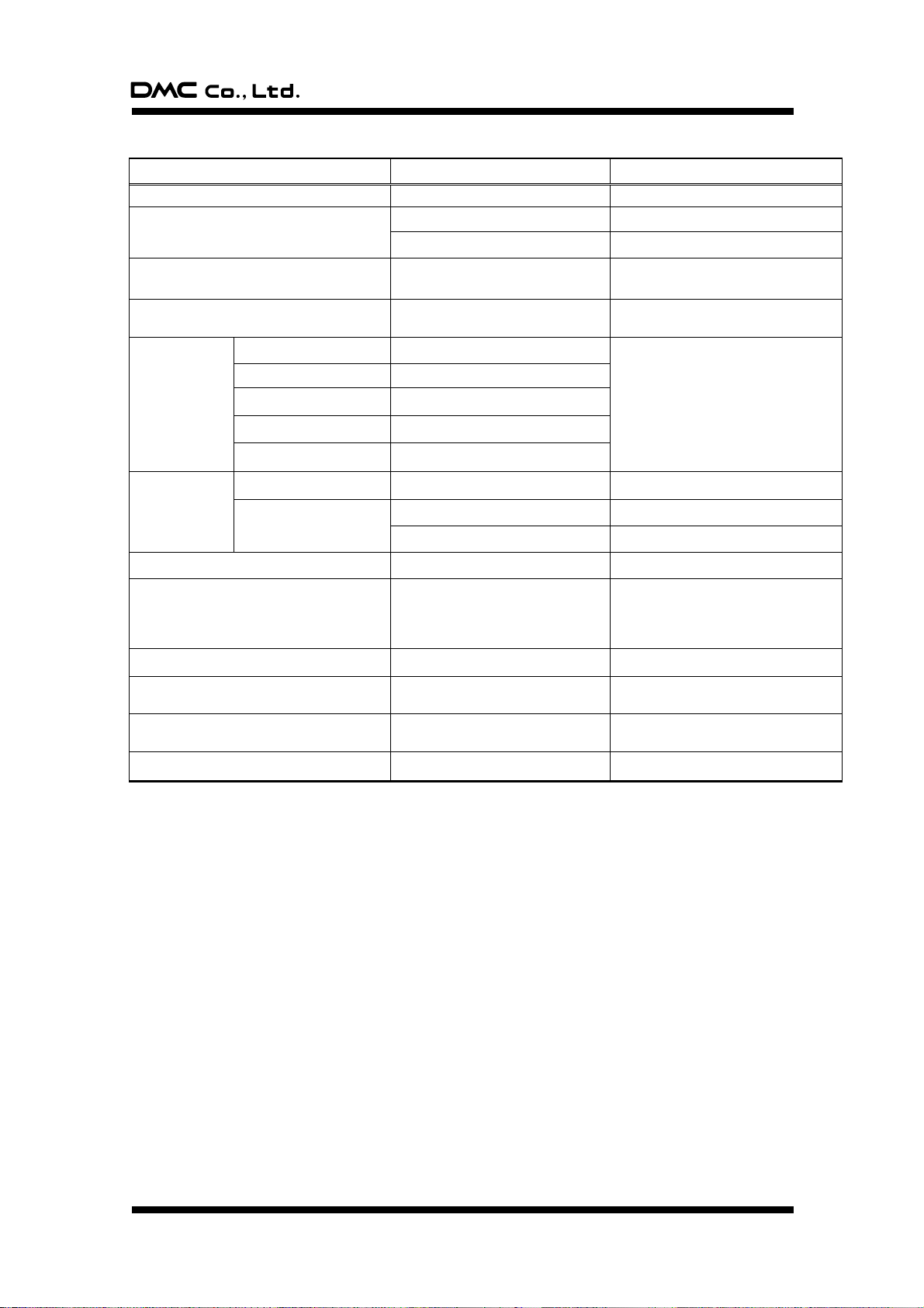
TSC-30/IC Product Specification
Item
Rating
Notes
Power supply voltage
DC 3.00V to 5.25V
Power consumption
125mW (standard)
Power supply voltage is 5V.
30mW (standard)
Power supply voltage is 3.3V.
Operating Temp
-20 ˚C to +85 ˚C
(No dew condensation)
Temperature range at storing
-40 ˚C to +125 ˚C
(No dew condensation)
Communication
scheme (serial)
Communication scheme
Asynchronous, serial
Each setting is fixed
Communication rate
9600bps
Data length
8bits
Stop bit
1bit
Parity
None
Communication
scheme (USB)
Transfer rate
USB Specification2.0 Full Speed
Transfer mode
Control transfer (command)
Interrupt transfer (coordinate)
Operation frequency
6MHz
Fixed to 6MHz
Coordinate output rate (point / second)
(1) Point mode
(2) 30p/s (3) 50p/s
(4) 80p/s (5) 100p/s
(6) 130p/s (7) 150p/s
Point Mode: Only when touch screen is
input, pen-down ID is sent once. After
input ends, no pen-up ID is sent.
Linearity error
±3 LSB
Input response time
10ms (TYP)
For coordinate mode, 150p/s,
Serial mode
Coordinate resolution
10bit (1024×1024)
In the correction data function,
resolution follows the setting value
Dimension (mm)
12×12×1.7
1-4. General specification
Document No. DER-S0098A 3 Version 1.3 ©2012 DMC Co., Ltd.
Page 5
TSC-30/IC Product Specification
INDEX
1 2 3 4 5 6 7
8
PANEL_AD_XL
PANEL_AD_XR
SW0
SW1
CNVss
RESET
TSC-30x
XXX ######
9
10
11
12
13
14
15
16
TrON
USBVref
Vcc
Vcc
Vss
LED2
LED1
24
23
22
21
20
19
18
17
32
31
30
29
28
27
26
25
PANEL_UR
PANEL_LL
PANEL_XR/LR
PANEL_XL/UR
PANEL_YU/UL
PANEL_YD/LL
D-
D+
Vcc
Vref
Vss
Xin
Xout
Vcc
Vss
LED0
JP3
JP4
JP5
JP6
JP7
JP8
PANEL_AD_YD
PANEL_AD_YU
57
58
59
60
61
62
63
64
49
50
51
52
53
54
55
56
EEP-CLK/JP10
EEP-CS/JP9
RxD
TxD
JP1
JP2
41
42
43
44
45
46
47
48
PANEL_THOb1
PANEL_THOa
PANEL_THI
EEP-DO/JP12
EEP-DI/JP11
RxD_I
BEEP
USB_PW
PEN_UP
PANEL_THOb3
PANEL_THOb2
33
34
35
36
37
38
39
40
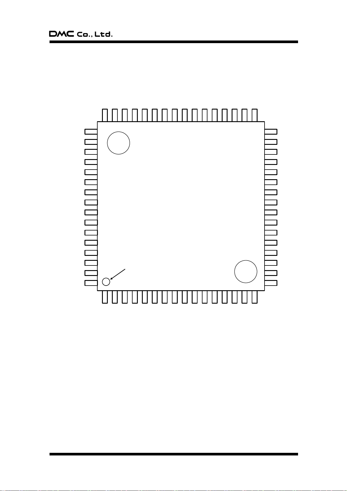
2. Pin layout and representation
Marking specification
TSC-30x Product number x: version number
xxx ROM number
###### Lot number
Document No. DER-S0098A 4 Version 1.3 ©2012 DMC Co., Ltd.
Page 6
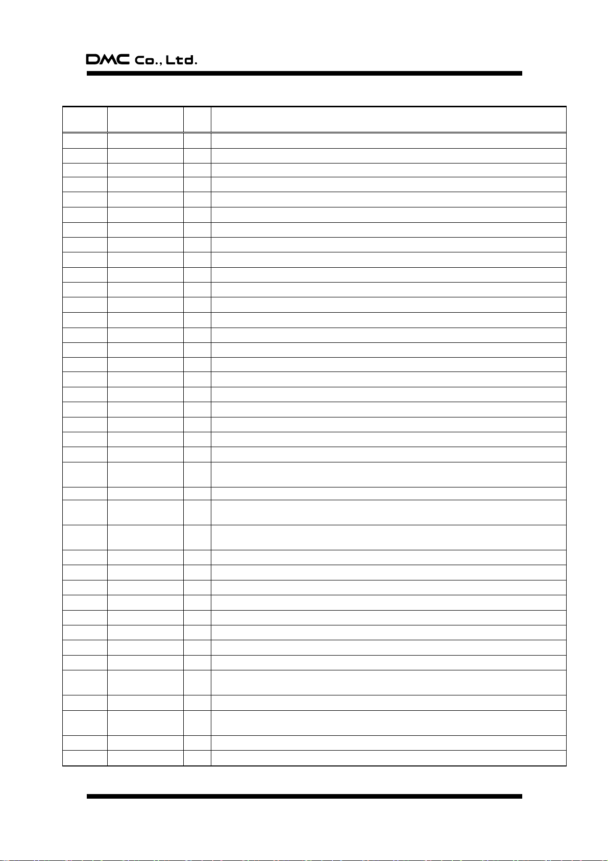
TSC-30/IC Product Specification
Pin
number
Pin name
I/O
Functional description
1
PANEL_AD_XL
I
Touch Screen XL input pin.
2
PANEL_AD_XR
I
Touch Screen XR input pin.
3
SW0
I
SW0 input pin; H=ON=1, L=OFF=0.
4
SW1
I
SW1 input pin; H=ON=1, L=OFF=0.
5 I
Unused pin. Via resistance; Vcc is connected.
6 I
Unused pin. Via resistance; Vcc is connected.
7
CNVss
P
Vss is connected.
8
RESET
I
Reset input pin (active L).
9
Vcc
P
Power supply input pin; Vcc is connected.
10
Vref
P
A/D converter reference voltage input pin; Vcc is connected.
11
Vss
P
Power supply input pin (GND); GND is connected.
12
Xin
I
Clock input pin; When using external clock, clock is input to this pin.
13
Xout
O
Clock output pin; When using external clock, this pin is opened.
14
Vcc
P
Power supply input pin; Vcc is connected.
15
Vss
P
Power supply input pin (GND); GND is connected.
16
LED0
O
LED output pin; When internal initialization was finished correctly, output L.
17
LED1
O
LED output pin; Touch input, ON=L, OFF=H.
18
LED2
O
LED output pin; When a response for the command is NAK, output L.
19 O
Unused pin; Opened.
20
Vss
P
Power supply input pin (GND); GND is connected.
21
Vcc
P
Power supply input pin; Vcc is connected.
22
Vcc
P
Power supply input pin; Vcc is connected.
23
USBVref
P
USB reference voltage input pin. If Vcc is 3.3V, Vcc is connected. If Vcc is 5V, GND is
connected via capacitor.
24
TrON
O
Identification signal for USB. D+ is connected via resistance (1.5k ohm).
25
D+
I/O
Data send/receive pin; In USB mode, D+ pin.
In serial mode, GND is connected via resistance (1k to 10k ohm).
26
D-
I/O
Data send/receive pin; In USB mode, D- pin.
In serial mode, GND is connected via resistance (1k to 10k ohm).
27
PANEL_YD/LL
O
Touch screen control pin.
28
PANEL_YU/UL
O
Touch screen control pin.
29
PANEL_XL/UR
O
Touch screen control pin.
30
PANEL_XR/LR
O
Touch screen control pin.
31
PANEL_LL
O
Touch screen control pin. Used only in 5-wire mode. In 4-wire/8-wire mode, opened.
32
PANEL_UR
O
Touch screen control pin. Used only in 5-wire mode. In 4-wire/8-wire mode, opened.
33 O
Unused pin; Opened.
34 O
Unused pin; Opened.
35
RxD_I
I
In power-save mode, start signal input pin by command reception. Only used serial
communication mode.
36
BEEP
O
BEEP output pin; H output. Output frequency=2.5KHz, Output time=50ms.
37
USB_PW
I
USB power supply detection pin. In USB mode, USB-Vbus is connected. *1
In serial mode, GND is connected.
38
PEN_UP
I
GND is connected.
39
PANEL_THOb3
I/O
Touch screen control pin. Used only in 5-wire mode. In 4-wire/8-wire mode, opened.
3. Pin functions
Document No. DER-S0098A 5 Version 1.3 ©2012 DMC Co., Ltd.
Page 7
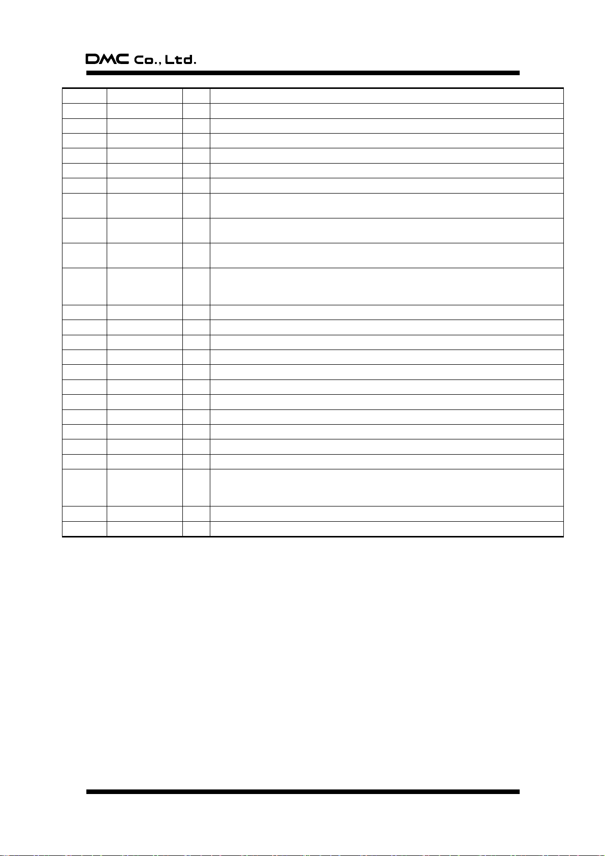
TSC-30/IC Product Specification
40
PANEL_THOb2
I/O
Touch screen control pin. Used only in 5-wire mode. In 4-wire/8-wire mode, opened.
41
PANEL_THOb1
I/O
Touch screen control pin. Used only in 5-wire mode. In 4-wire /8-wire mode, opened.
42
PANEL_THOa
I/O
Pen down detection pin.
43
PANEL_THI
I
In power-save mode, start signal input pin by pen down.
44 O
Unused pin; Opened.
45 O
Unused pin; Opened.
46 O
Unused pin; Opened.
47
EEP-DO/JP12
I/O
Vcc is connected.
When using EEPROM, EEPROM DO is connected.
48
EEP-DI/JP11
I/O
When using EEPROM, EEPROM DI is connected.
When not using EEPROM, Vcc is connected via resistance.
49
EEP-CLK/JP10
I/O
When using EEPROM, EEPROM SK is connected.
When not using EEPROM, Vcc is connected via resistance.
50
EEP-CS/JP9
I/O
EEPROM setting pin shared with EEPROM CS signal output pin.
EEPROM is set via resistance and Vcc or GND is connected. (L=Used, H=Not used)
When using EEPROM, EEPROM CS is connected.
51
RxD
I
In serial mode, data receive pin. In USB mode, Vcc is connected via resistance.
52
TxD
O
In serial mode, data send pin. In USB mode, opened.
53 O
Unused pin; Opened.
54 O
Unused pin; Opened.
55
JP1
I
GND is connected.
56
JP2
I
GND is connected.
57
JP3
I
GND is connected.
58
JP4
I
Panel ID select pin.
59
JP5
I
Panel ID select pin.
60
JP6
I
Touch screen mode setting pin; L=4 / 8 wire, H=5-wire
61
JP7
I
Touch screen mode setting pin; L=4 / 5 wire, H=8-wire
62
JP8
I
In USB mode, if Vcc is 5V, Vcc is connected via resistance. If Vcc is 3.3V, GND is
connected.
In serial mode, Vcc is connected via resistance or GND is connected.
63
PANEL_AD_YD
I
Touch Screen YD input pin.
64
PANEL_AD_YU
I
Touch Screen YU input pin.
*1: Please be careful if you use a external power supply not to exceed the power supply voltage in this
terminal.
Document No. DER-S0098A 6 Version 1.3 ©2012 DMC Co., Ltd.
Page 8
TSC-30/IC Product Specification
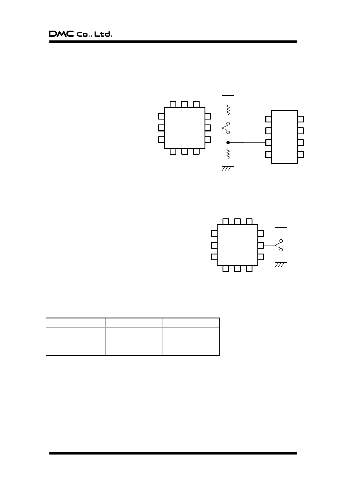
USB_PW
USB Vbus
L= Serial
H = USB
(TSC-30/IC)
EEP-CS/JP9
VCC
L= Used
H= Not used
CS
(TSC-30/IC)
(EEPROM)
Mode
Pin number 60
Pin number 61
4-wire touch screen
GND
GND
5-wire touch screen
Vcc
GND
8-wire touch screen
GND
Vcc
4. Initial setting
4-1. EEPROM setting
Depending on that calibration is performed in either TSC-30/IC or host, you can select whether EEPROM
is used or not to store the correction data. EEPROM selection can be set via pin number 50, where
hardware reset release enables the setting.
4-2. Communication mode setting
Communication mode setting for serial/USB is performed by setting pin number 37 to “H” or “L”. When
power supply is turned on, or hardware reset is released, pin number 37 is read to turn on in either USB/
serial mode.
No both communication schemes are used at a time. After the
hardware reset, if setting is performed with jumper switch, the
setting is enabled by power supply restart or hardware reset.
4-3. Touch screen mode setting
Touch screen mode setting for 4-wire, 5-wire or 8-wire is performed by setting pin number 60 and 61 to “H”
or “L”. When power supply is turned on, or hardware reset is released, pin number 60 and 61 are read to
turn on in either 4-wire, 5-wire or 8-wire mode.
Document No. DER-S0098A 7 Version 1.3 ©2012 DMC Co., Ltd.
Page 9
TSC-30/IC Product Specification
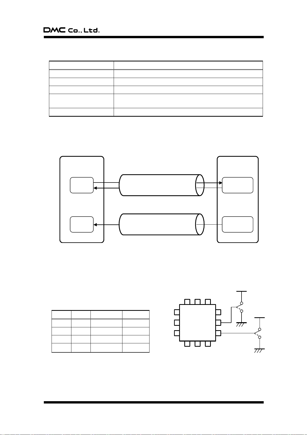
JP4
VCC
(TSC-30/IC)
VCC
JP5
H
L
H
L
Item
Specification
USB standard
Specification Rev2.0 Full Speed
Power supply
Bus power supply / Self-Power
Device class
Vendor definition
Interrupt (coordinate)
transfer interval
1ms
End point buffer size
EP0: 8byte EP1: 5byte (EP0: control transfer, EP1: interrupt transfer)
JP4
JP5
iProduct
Panel ID
L L 00h
0
H L 01h
1
L H 02h
2
H H 03h
3
Host
TSC-30/IC
End Point 0
IN/OUT
Control transfer
(Descriptor, Device Request (command))
Interrupt transfer
(Coordinate data)
End Point 1
IN
Buffer
Buffer
4-4. Configuration in USB mode
§ Basic configuration
§ Connection with Host
Coordinate data, correction value or other various output data are all output to the host as a response
to IN token. Output coordinate in coordinate data mode and correction data mode is output in the
interrupt transfer, while other data is output to the host with control transfer.
4-5. Panel ID setting (USB mode)
If two (three or four) touch screens to the same host are connected simultaneously, each TSC-30/IC to the
host needs panel ID setting. This function is enabled in the USB mode, by setting pin number 58 (JP4) and
pin number 59 (JP5) to “ H” or “ L” . Setting is enabled when hardware is reset, where Device
Descriptor’ s iProduct is set to “ 0” or “ 1” and this value
is identified by the host as panel ID.
Document No. DER-S0098A 8 Version 1.3 ©2012 DMC Co., Ltd.
Page 10
TSC-30/IC Product Specification
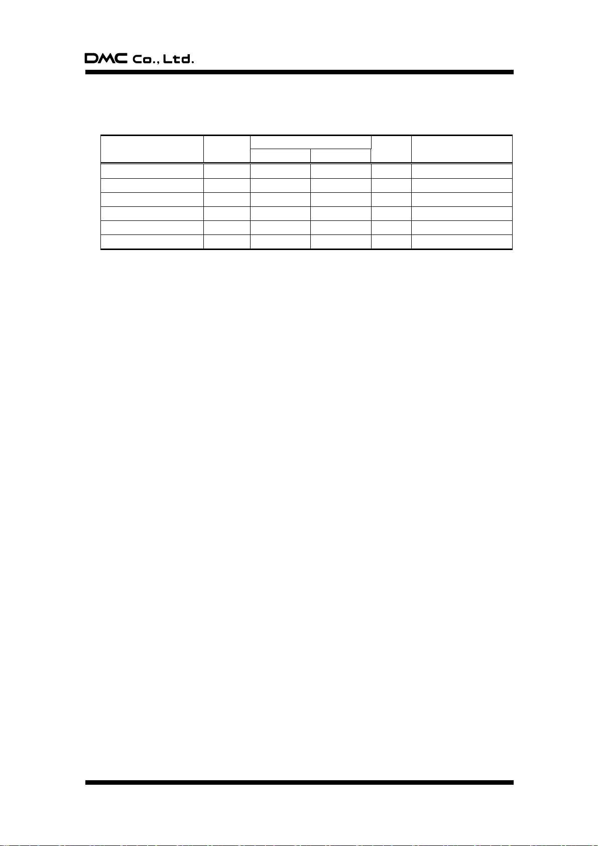
Item
Symbol
Ratings
Unit
Description
Minimum
Maximum
Power supply voltage
VCC
-0.3
6.5
V
Input voltage
VI
-0.3
Vcc+0.3
V
Output voltage
VO
-0.3
Vcc+0.3
V
Power consumption
PD 500
mW
Ta=25˚C
Operation temperature
TOPR
-20
+85
˚C
Storage temperature
TSTG
-40
+125
˚C
5. Data sheet
5-1. Absolute maximum rating
Document No. DER-S0098A 9 Version 1.3 ©2012 DMC Co., Ltd.
Page 11
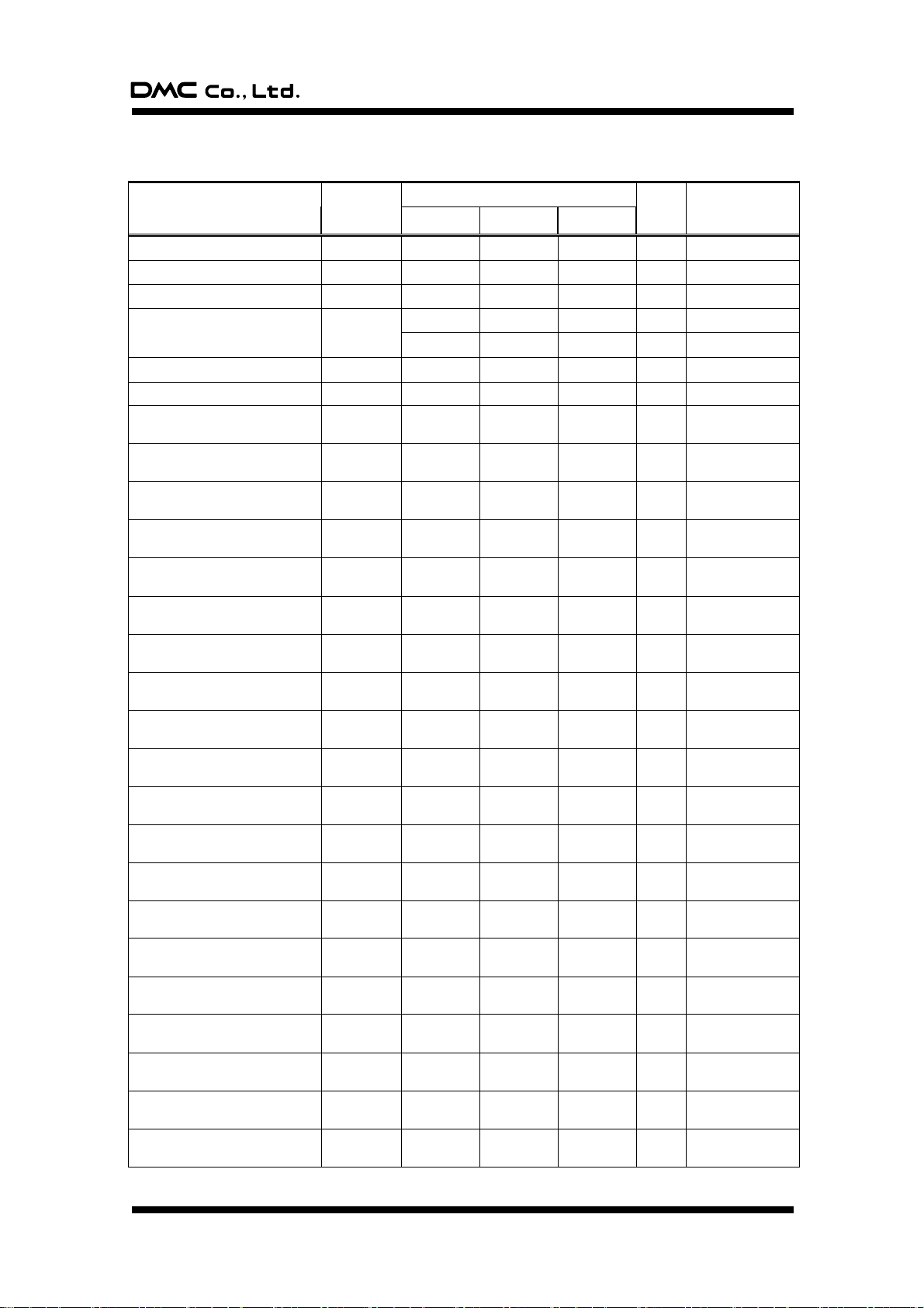
TSC-30/IC Product Specification
Item
Symbol
Limits
Unit
Description
Minimum
Standard
Maximum
Power supply voltage
Vcc
3.00
5.00
5.25 V
Analog reference voltage
AVcc Vcc
V
Analog reference voltage
AVREF
2.0 Vcc V
Analog reference voltage USB
USBVREF
3.0 3.6
V
Vcc=3.6 to 4.0V
3.0 Vcc
V
Vcc=3.0 to 3.6V
Power supply voltage
Vss 0 V
Analog reference voltage
AVss 0 V
“H” input voltage
(Pin number 16-19, 27-50)
VIH
0.8Vcc
Vcc V
“H” input voltage
(Pin number 1-6, 51-64)
VIH
0.8Vcc
Vcc V
“H” input voltage
RESET, XIN, Pin number 7, 15
VIH
0.8Vcc
Vcc V
“H” input voltage
D+, D-
VIH
2.0 3.6 V
“L” input voltage
(Pin number 16-19, 27-50)
VIL 0
0.2Vcc V
“L” input voltage
(Pin number 1-6, 51-64)
VIL 0
0.2Vcc V
“L” input voltage
RESET, XIN, Pin number 7, 15
VIL 0
0.2VCC V
“L” input voltage
D+, D-
VIL 0
0.8 V
“H” output total peak current *1
(Pin number 16-19, 27-50)
IOH (peak)
-80
mA
“H” output total peak current *1
(Pin number 1-6, 51-64)
IOH (peak)
-80
mA
“L” output total peak current *1
(Pin number 27-50)
IOL (peak)
80
mA
“L” output total peak current *1
(Pin number 16-19)
IOL (peak)
80
mA
“L” output total peak current *1
(Pin number 1-6, 51-64)
IOL (peak)
80
mA
“H” output total average current*1
(Pin number 16-19, 27-50)
IOH (avg)
-40
mA
“H” output total average current*1
(Pin number 1-6, 51-64)
IOH (avg)
-40
mA
“L” output total average current*1
(Pin number 27-50)
IOL (avg)
40
mA
“L” output total average current*1
(Pin number 16-19)
IOL (avg)
40
mA
“L” output total average current *1
(pin number 1-6, 51-64)
IOL (avg)
40
mA
“H” output peak current *2
(Pin number 16-19, 27-50)
IOH (peak)
-10
mA
“H” output peak current *2
(Pin number 1-6, 51-64)
IOH (peak)
-10
mA
5-2. Recommended operational conditions
Document No. DER-S0098A 10 Version 1.3 ©2012 DMC Co., Ltd.
Page 12

TSC-30/IC Product Specification
“L” output peak current *2
(Pin number 27-50)
IOH (peak)
10
mA
“L” output peak current *2
(Pin number 16-19)
IOH (peak)
20
mA
“L” output peak current *2
(Pin number 1-6, 51-64)
IOH (peak)
10
mA
“H” output average current *3
(Pin number 16-19, 27-50)
IOH (avg)
-5
mA
“H” output average current *3
(Pin number 1-6, 51-64)
IOH (avg)
-5
mA
“L” output average current *3
(Pin number 27-50)
IOL (avg) 5 mA
“L” output average current *3
(Pin number 16-19)
IOL (avg)
10
mA
“L” output average current *3
(Pin number 1-6, 51-64)
IOL (avg) 5 mA
Vibration frequency *4
XIN
6.0
MHz
In USB mode
Tolerance:±0.25%
*1 The total peak output current is the absolute value of the peak currents flowing through all the
applicable ports. The total average output current is the average value of the absolute value of the
currents measured over 100ms flowing through all the applicable ports.
*2 The peak output current is the absolute value of the peak current flowing in each port.
*3 The average output current is the average value of the absolute value of the currents measured over
100ms.
*4 The duty of oscillation frequency is 50%.
Document No. DER-S0098A 11 Version 1.3 ©2012 DMC Co., Ltd.
Page 13
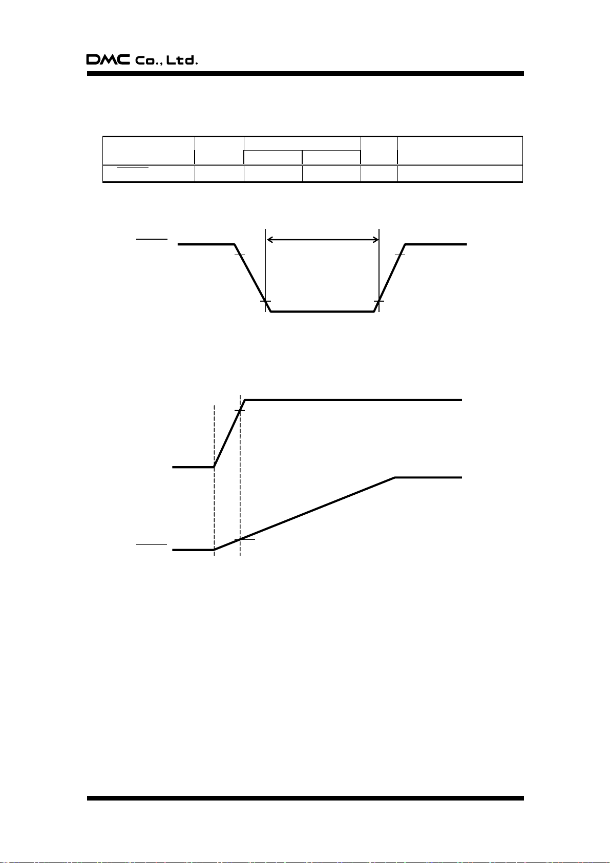
TSC-30/IC Product Specification
Item
Symbol
Limits
Unit
Description
Minimum
Maximum
RESET L width
tw 2
μs
RESET
0.2Vcc
0.8Vcc
0.2Vcc
0.8Vcc
tw
≦0.2Vcc
3.0V
VCC
RESET
(PWR ON)
Reset release voltage: Vcc = 3.0V
5-3. Timing requirement
§ Reset
(Vcc = 3.0 to 5.25V , Vss = 0V , Ta = -20 to 85°C)
§ Power-on reset
Reset input voltage shall be 0.6V or below at the timing when power supply voltage crosses 3.0V.
(Ta = -20 to 85°C)
Document No. DER-S0098A 12 Version 1.3 ©2012 DMC Co., Ltd.
Page 14
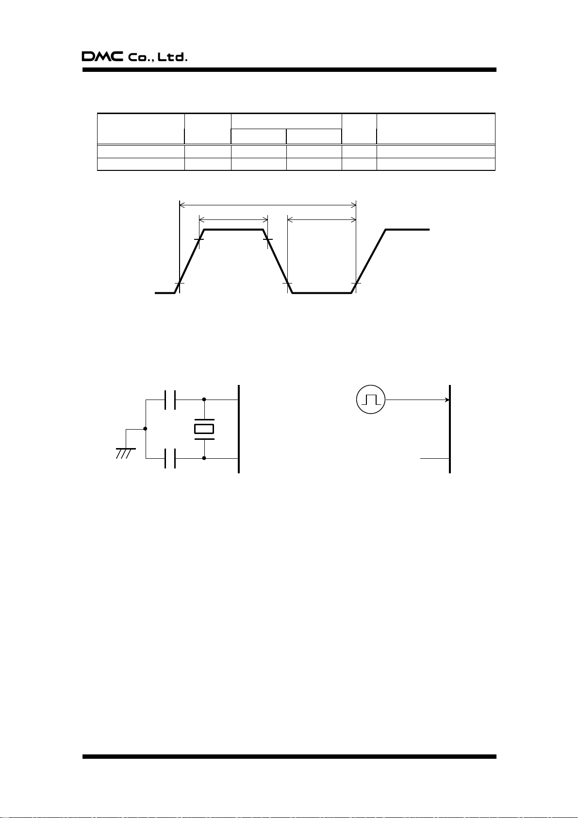
TSC-30/IC Product Specification
Item
Symbol
Limits
Unit
Description
Minimum
Maximum
Input cycle
tC
166
ns
Clock Frequency Fixed to 6MHz
Clock pulse width
tWH, tWL
70
ns
XIN
XOUT
CIN
COUT
Using ceramic vibrator
XIN
XOUT
Open
External clock input circuit
XIN
0.2VCC
tWH
tWL
0.8VCC
tC
§ External clock timing
§ Clock input circuit
Document No. DER-S0098A 13 Version 1.3 ©2012 DMC Co., Ltd.
Page 15
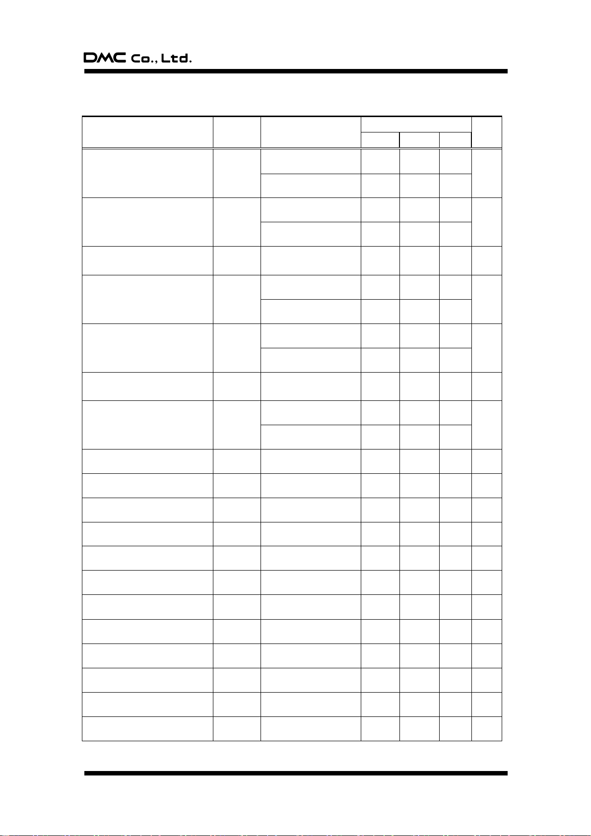
TSC-30/IC Product Specification
Item
Symbol
Condition
Limits
Unit
Minimum
Standard
Maximum
“H” Output voltage
(Pin number 16-19, 27-50)
VOH
IOH = -10mA
VCC = 4.0 to 5.25V
Vcc-2.0
V
IOH = -1.0mA
VCC-1.0
“H” Output voltage
(Pin number 1-6, 51-64)
VOH
IOH = -10mA
VCC = 4.0 to 5.25V
Vcc-2.0
IOH = -1mA
Vcc-1.0
“H” Output voltage
(Pin number. 25 (D+), 26 (D-))
VOH
Pull-down with 0V via a
resistor of 15kΩ±5%
2.8 3.6
V
“L” Output voltage
(Pin number 27-50)
VOL
IOL = 10mA
VCC = 4.0 to 5.25V
2.0
V
IOL = 1mA
1.0
“L” Output voltage
(Pin number 16-19)
VOL
IOL = 20mA
VCC = 4.0 to 5.25V
2.0
V
IOL = 1mA
1.0
“L” Output voltage
(Pin number. 25 (D+), 26 (D-))
VOL
Pull-up with 3.6V via a
resistor of 15kΩ±5%
0.3
V
“L” Output voltage
(Pin number 1-6, 51-64)
VOL
IOL = 10mA
VCC = 4.0 to 5.25V
2.0
V
IOL = 1mA
1.0
hysteresis
(Pin number 35-37)
VT+ - VT-
0.6 V
hysteresis
(Pin number 1-6, 51-64)
VT+ - VT-
0.6 V
hysteresis
(Pin number 25(D+), 26(D-))
VT+ - VT-
0.25 V
hysteresis
(Pin number 8)
VT+ - VT-
0.5 V
“H” Input current
(Pin number 16-19, 27-50)
IIH
VI = VCC
5.0
μA
“H” Input current
(Pin number 1-6, 51-64)
IIH
VI = VCC
5.0
μA
“H” Input current
(Pin number 7, 8)
IIH
VI = VCC
5.0
μA
“H” Input current
(Pin number 12)
IIH
VI = VCC
4.0
μA
“L” Input current
(Pin number 16-19, 27-50)
IIL
VI = VSS
-5.0
μA
Input “L” current
(Pin number 1-6, 51-64)
IIL
VI = VSS
-5.0
μA
Input “L” current
(Pin number 7, 8, 15)
IIL
VI = VSS
-5.0
μA
Input “L” current
(Pin number 12)
IIL
VI = VSS
-4.0 μA
5-4. DC standards
(Vcc=3.00 to 5.25V, Vss=0V, Ta=-20 to 85˚C, unless otherwise noted)
Document No. DER-S0098A 14 Version 1.3 ©2012 DMC Co., Ltd.
Page 16
TSC-30/IC Product Specification
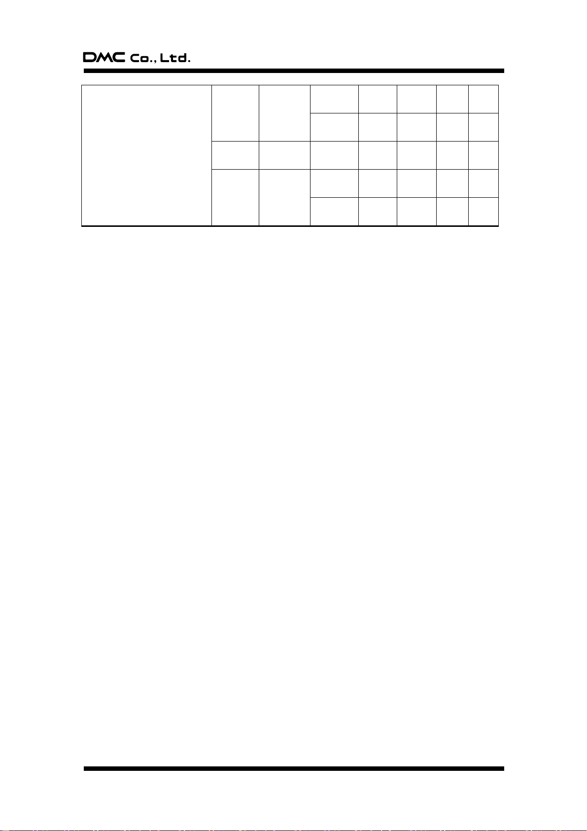
Power supply current
Icc1
Normal
mode
*1
Vcc=
4.0 to 5.25V
2.1
60
mA
Vcc=
3.0 to 4.0V
35
mA
Icc2
STOP mode
*2
Vcc=
3.0 to 5.25V
2.0 mA
Icc3
At USB
suspend
mode*3
Vcc=
4.0 to 5.25V
125.0
250
uA
Vcc=
3.0 to 5.25V
0.1 uA
*1: All USB difference-input circuits enabled. Leaving I/O pins open. Operating functions: CPU, Timers
*2: All USB difference-input circuits enabled. Leaving I/O pins open. Operating functions: Timers, USB
receiving. Disabled functions: CPU.
*3: All USB difference-input circuits disabled. Leaving I/O pins open. Oscillation stopped.
Document No. DER-S0098A 15 Version 1.3 ©2012 DMC Co., Ltd.
Page 17
TSC-30/IC Product Specification
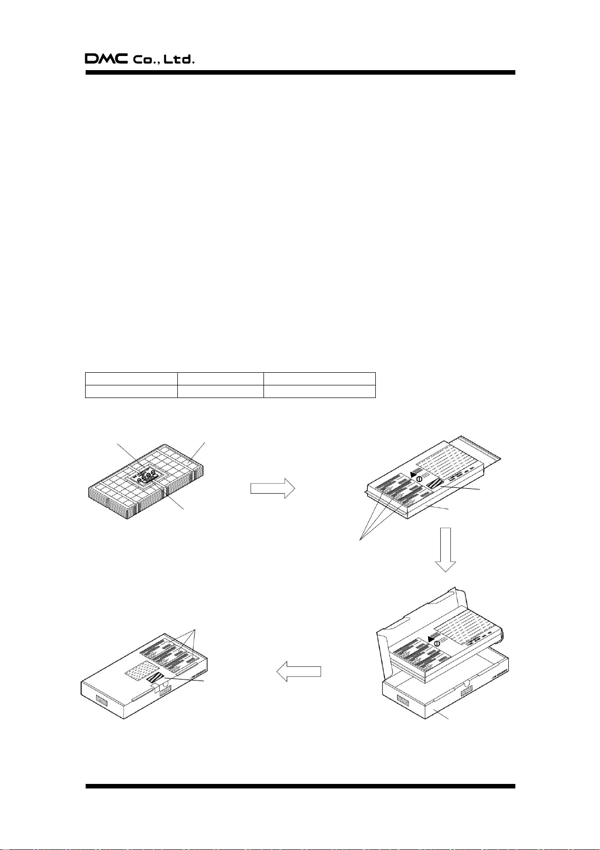
Quantity per tray
Number of trays
Quantity per packages
160
5 + 1(cover)
800
Desiccant
Tray
Humidity indicator
Packaging label
Aluminum laminate bag
Packaging box
Packaging label
Product name label
Product name
label
6. Packaging Specification
6-1. Outline
With a basic packaging unit of 800, TSC-30/IC is packaged for the number of 800 and its multiple using
damp-proof aluminum laminate bags (Basic packaging). If the delivery quantity is less than 800 or not
multiple of 800, or the product can not be packaged with a unit of 800, then no damp-proof packaging
specification is applicable (Small group packaging).
If packaged with small group packaging, the products may be dampened. Before packaging, the product
shall take the baking process as specified in [Baking] defined in “7. Storage Specification”.
6-2. Notes on storage/handling
(1) Handle the packages with care and avoid throwing and dropping them. Or, a large impact may be
imposed, causing packaging material’s damage, broken package or bending lead.
(2) Cardboard box may be deteriorated in its strength and deformed due to storage site’s humidity,
stacking condition and storage duration. It is desirable to keep the storage under normal
temperature/humidity (5 to 35 C, 45 to 75%RH). For warehousing, follow the FIFO principle.
(3) After unpacking, be careful in handling the product to avoid electrostatic breakdown.
6-3. Basic packaging
6-3-1. Packaging type
Damp-proof packaging (Aluminum laminate bag)
6-3-2. Packaging quantity specification
Document No. DER-S0098A 16 Version 1.3 ©2012 DMC Co., Ltd.
Page 18
TSC-30/IC Product Specification
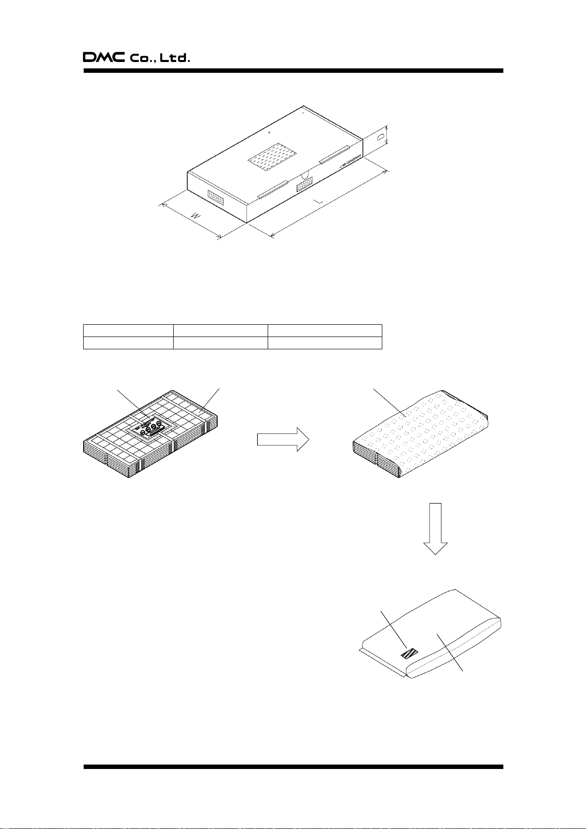
Quantity per tray
Number of trays
Quantity per packages
160
1 – 5 + 1(cover)
1 - 799
Desiccant
Number of trays: 1 to 5
(Additionally, one dummy tray pl
aced at the top for reinforcing)
Air cap
Product name label
Antistatic bag
L: 351 W: 148 D: 55 (mm)
* No sizes specified for packaging box (Cardboard
box) used for transportation.
6-3-3. Diagram for packaging box sizes
6-4. Small group packaging
6-4-1. Packaging type
General packaging (No damp-proof processing)
6-4-2. Packaging quantity specification
Document No. DER-S0098A 17 Version 1.3 ©2012 DMC Co., Ltd.
Page 19
TSC-30/IC Product Specification
6-5. Tray specification
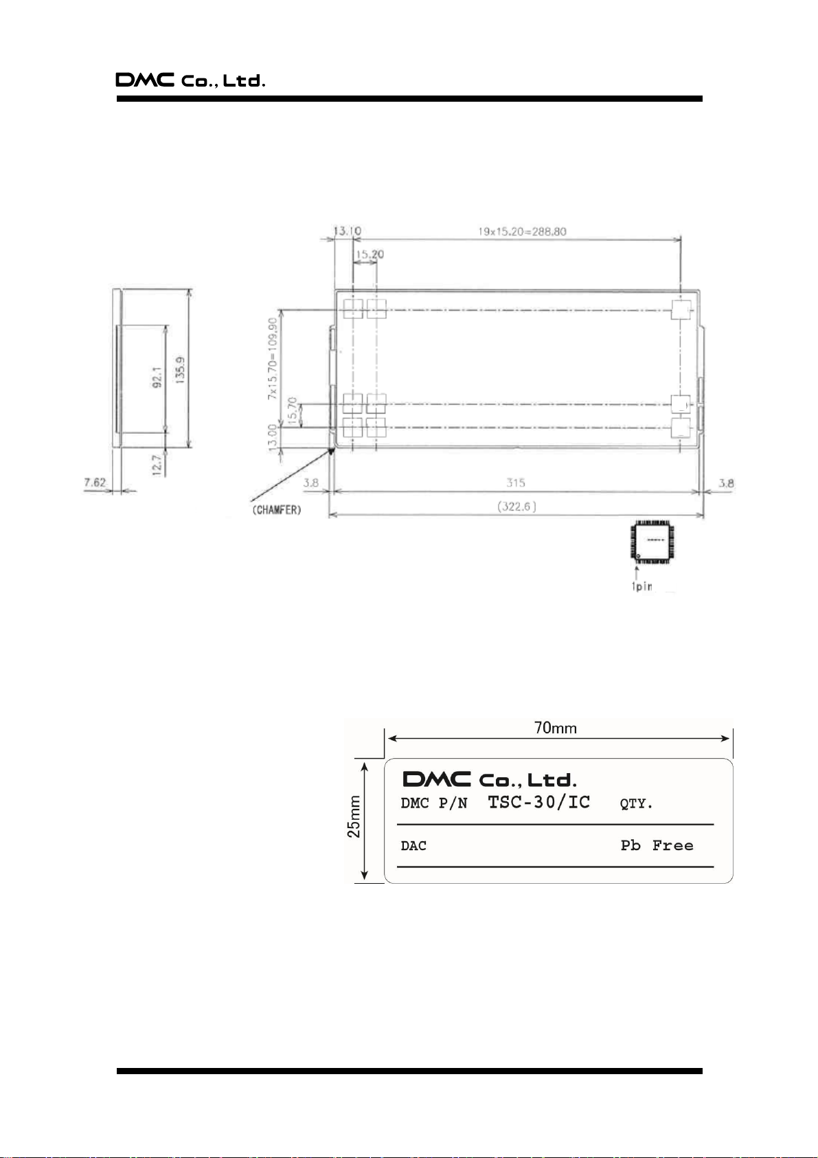
This tray is heat-proof type, allowing the heating with 125 C for 24 hours. During heating/cooling process,
however, bending may occur. In baking process, to minimize the bending, heat and cool the tray by placing
it on a flat plate.
6-6. Product name label specification
DMC P/N: Product number (TSC-30/IC)
QTY: Quantity
DAC: DMC Control Number
Document No. DER-S0098A 18 Version 1.3 ©2012 DMC Co., Ltd.
Page 20

TSC-30/IC Product Specification
7. Storage Specification
7-1. Storage Conditions
For storing the product until its implementation, it is recommended that the following storage conditions are
applied:
1. Before unpacking the damp-proof package (Aluminum laminate bag)
Temperature and humidity: 5 to 40 C, 20 - 80%RH
Duration: Two years or less
2. After unpacking the damp-proof package (Aluminum laminate bag)
For the storing duration after the damp-proof package is unpacked and before the implementation, it is
recommended that the following storage conditions is to be applied:
(1) Reflow method: Two weeks or less under the ambient condition: 30 C, 70%RH or less
3. Temporary storage after damp-proof package is unpacked
To store again temporarily the once unpacked and unused damp-proof package, it is recommended to
pack it again into another damp-proof bag with desiccant within a shorter time after opened (Around 10
minutes) as far as possible, and fold the bag’s opening, followed by sealing with adhesive material
such as adhesive tape, then store it under the following conditions:
Temperature, humidity: 5 to 40 C, 20 - 80%RH
Duration: One month or less
7-2. Baking
If any condition among those 1 to 3 listed below is applicable, it is recommended to apply the baking as
described below to dry the moisture the package absorbs.
You may place the tray used for damp-proof packaging directly into the thermostatic chamber since the
tray is heat-proof type. When placing into the chamber or after removing from it, to avoid deformation, cool
the tray by placing it on the flat plate such as surface table.
1. Any condition among 1 to 3 in [7-1. Storage condition] is unsatisfied
2. Indicator’s 30% Humidity Check section changes the color to lavender or pink
3. Blue color indicator of desiccant (Silica gel) changes to pink or white
Baking method
Temperature: 125 C
Duration: 20 to 24 hours
Frequency: Four times or less (Upper limit: 96 accumulative hours)
Document No. DER-S0098A 19 Version 1.3 ©2012 DMC Co., Ltd.
Page 21
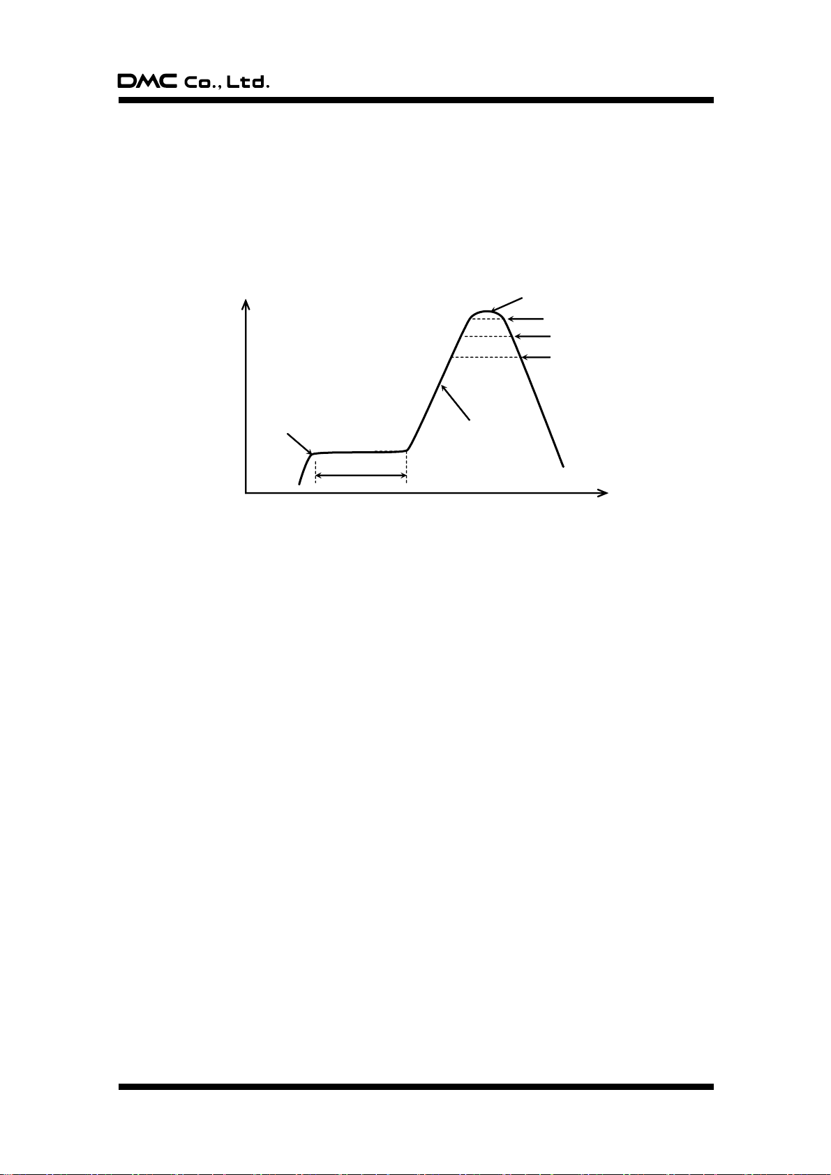
TSC-30/IC Product Specification
11020s
17510 C
1 to 4 C/s
220 C or higher, 50s max.
255 C or higher, 10s max.
260 C max.
Time
Package’s surface temperature
200 C or higher, 70s max.
8. Implementation Temperature Specification
We do not recommend the wave soldering method.
1. Reflow method (Infrared reflow, air reflow)
Frequency: Three times or less
Temperature: The following device surface temperature profile is recommended.
Figure 1: Infrared reflow, air reflow temperature profile
2. Soldering iron (Manual soldering)
Soldering bit’s temperature: 370 C or lower
Soldering time: Five seconds or less/terminal
Document No. DER-S0098A 20 Version 1.3 ©2012 DMC Co., Ltd.
Page 22

TSC-30/IC Product Specification
Base material
:Cu
Coat
:Sn-1.5%Cu
Thickness of coat
:5um or above
9. Terminal Pin Specification
10. Cleaning
In case of cleaning boards with solvents after soldering, following items should be taken attention.
*Administrative guidance and regulation.
*Residual ionic (non ionic) contamination.
*Solvent resistance of parts.
Document No. DER-S0098A 21 Version 1.3 ©2012 DMC Co., Ltd.
Page 23

TSC-30/IC Product Specification
11.Changes and improvements
11-1. Version history
§ TSC-30/IC
Ver0.1 (July 31, 2007)
Draft release
Ver0.2 (September 27, 2007)
2. Pin layout Pin layout was changed. (SW0, SW1, LED0, LED2, RxD_I)
3. Pin functions Pin functions were changed. (LED0, LED2, USB_PW, EEP-DI/JP11,
EEP-CLK/JP10, JP3, JP8)
4-2. Communication mode setting Terminal number was changed from 57 to 37.
4-5. Panel ID setting (USB mode) Replaced setting of JP4 with JP5.
“6. Packing Specification” was added.
“7. Storage Specification” was added.
“8. Implementation Temperature Specification” was added.
“9. Cleaning” was added.
Ver0.3 (November 29, 2007)
1-2. Outline 8-wire touch screen was added.
3. Pin function Pin functions were changed. (USBVref, USB_PW, JP6, JP7)
4-3. Touch screen mode setting 8-wire touch screen mode was added.
6-6. Product name label specification “Pb Free” was added.
Circuit Diagram In USB mode, Vcc is 3.3V, it changed the circuit of the USB_PW terminal.
Circuit Diagram A capacitor was added to a power I/F circuit.
Ver 1.0 (March 13, 2008)
First release
(Change from ver0.3.)
1-4. General specification Input response time was added.
2. Pin layout and representation Marking specification was changed.
3. Pin functions “8-wire” was added.
3. Pin functions “Sleep mode” was changed to “Power save mode”.
4-2. Communication mode setting “Vcc” was changed to “USB Vbus”.
5-2. Vibration frequency “In USB mode, Tolerance:±0.25%” was added.
9. Terminal Pin Specification was added.
Circuit Diagram In USB mode, Self-powered mode was added.
Circuit Diagram In USB mode, the part number of the resonator was changed.
Circuit Diagram Revision 1 for first release.
Document number was added.
Ver 1.1 (July 9, 2009)
5-2. 5-3. 5-4. “Rating” was changed to “Limits”.
5-3. Timing requirement “External clock timing” “Fixed to 6MHz” was added.
Dimensional Drawing The size of the width of the terminal “bp” was added.
Document No. DER-S0098A 22 Version 1.3 ©2012 DMC Co., Ltd.
Page 24

TSC-30/IC Product Specification
Ver1.2 (November 10, 2010)
1-4. General specification Operation Temp: USB changed to -20 ˚C to +85 ˚C
3. Pin functions Pin No.36 (BEEP) “Output frequency=2.5KHz, Output time=50ms” was added.
Circuit Diagram Transistor number was added. (Rev2)
Ver1.3 (May 25, 2012)
Address has changed as Tokyo office had moved
Document No. DER-S0098A 23 Version 1.3 ©2012 DMC Co., Ltd.
Page 25

TSC-30/IC Product Specification
12. Warranty
12-1. Warranty Period
§ The warranty period is limited to 1 year from the date of shipping. The warranty for the initial defection
such as appearance defection is limited to 1 month.
§ Any defected parts under proper use will be examined by the supplier and replaced by the new parts if
the defection is considered to be caused by the supplier.
§ The replacement is subject to be included in the next lot.
12-2. Warranty Target
§ The warranty only covers the product itself and does not cover any damage to others caused by using
this product. Onsite repair or replacement is not supported.
§ We will do our best for delivery problem and product defections, but the warranty for the production line
is not covered.
12-3. Warranty Exceptions
Following conditions are not covered with the warranty and subject to charge.
§ Any malfunctions and damages during transportation and transfer by the user.
§ Any malfunctions and damages caused by a natural disaster or a fire.
§ Any malfunctions and damages caused by static electricity
§ Any malfunctions and damages caused by the failure of the associated equipment.
§ If the product is remodeled, disassembled or repaired by the user.
§ If the product is glued onto the equipment and uninstalled.
§ Any malfunctions and damages caused by an improper usage and handling against the specifications
and notes.
Document No. DER-S0098A 24 Version 1.3 ©2012 DMC Co., Ltd.
Page 26
TSC-30/IC Product Specification
13. Notes on use
13-1. Overall handling
§ When using the product, do not place it close to, or make it contact with, the conductive materials such
as metal.
§ Do not touch the metal part in the product directly with your hands. Or, it may be destructed by the static
electricity. If you contact, or may contact, it directly with your hand, prepare in advance the measure
against static electricity.
§ To store the product, use an appropriate packing box and keep the storage temperature range with no
overload on it.
§ In using the product or storing it, avoid the following conditions:
- Conditions where water is, or may be, attached to the product.
- Conditions where condensation takes place, or may take place.
- In the ambience of organic solvent or acidity or contact, or where the product contacts them.
§ Do not alter or disassemble the product.
13-2. Others
§ This specification may be changed for improvement without prior notices.
§ No liabilities are taken by us for any damage caused by use of this product.
§ This product intends to be used for the standard applications (e.g. office equipment and OA devices,
industrial use, communication devices, household equipment). Avoid its use where failure or malfunction
directly may affect the human body or special applications where extremely high reliability is required
(e.g. airline and space industries, nuclear controls, medical use for life-sustaining).
§ Semi-conductor devices may fail in a certain possibility. Keep the safety design in your mind so that
possible failure in this product shall not cause physical accidents such as injury and death, fire and other
social damages.
TSC-30/IC Product Specification
Version 1.3: Issued at May 25, 2012
©2012 DMC Co., Ltd.
This document is allowed to redistribute but no alteration, part or all, is prohibited.
http://www.dmccoltd.com/english/
11F Nisseki Takanawa Bldg., 2-18-10 Takanawa, Minato-ku, Tokyo 108-0074, Japan
Phone: +81-3-6721-6731 (Japanese), 6736 (English) Fax: +81-3-6721-6732
Document No. DER-S0098A 25 Version 1.3 ©2012 DMC Co., Ltd.
Page 27
Page 28
Page 29
Page 30
Page 31
Page 32
Page 33
Page 34
Page 35
Page 36
Page 37
Page 38
Page 39
 Loading...