

Page 1
PH1005
POWER CRIMP TOOL
INTRODUCTION
The PH1005Power Crimp Tool is a pneumatic / hydraulic powered version of the Tyco®49935 hand crimp tool. The
basic system consists of a hand held tool (PHMT1005) and the PHRPU4 Remote Power Unit. The Remote Power
Unit contains cycle control logic that assures the tool completes the crimp cycle without operator intervention.
IMPORTANT SAFETY INSTRUCTIONS / USER’S RESPONSIBILITIES
When connected together, the PHMT1005 along with the remote power unit, constitute an integrated operating
system. Under no circumstances should the crimping tool be attached to any control box or power system other than
the control unit provided (PHRPU4). It is imperative that operators using this tool system follow the noted Safety
Precautions, be alert at all times and observe the highest level of operator safety.
1. Disconnect from air supply when tool is not in use or when changing dies.
2. Keep all body parts clear of the crimping area while loading and operating the tool.
3. Restrict operation of the PH1005 system to a single operator and follow the directions on the warning labels.
4. Do not alter the tool or operate outside the guidelines specified in this data sheet.
Itis the user’s responsibility to properly train andinstruct alltool operatorsinthe proper use of this tool.
The operator must be made aware of the danger of the moving parts, the possibility of serious injury to
fingers and other body parts in inserted into the crimp area; and the need to be alert and attentive at all
times while using this tool.
SAFETY OPERATION MANUAL
PREPARING TOOL FOR OPERATION (see Figure 1)
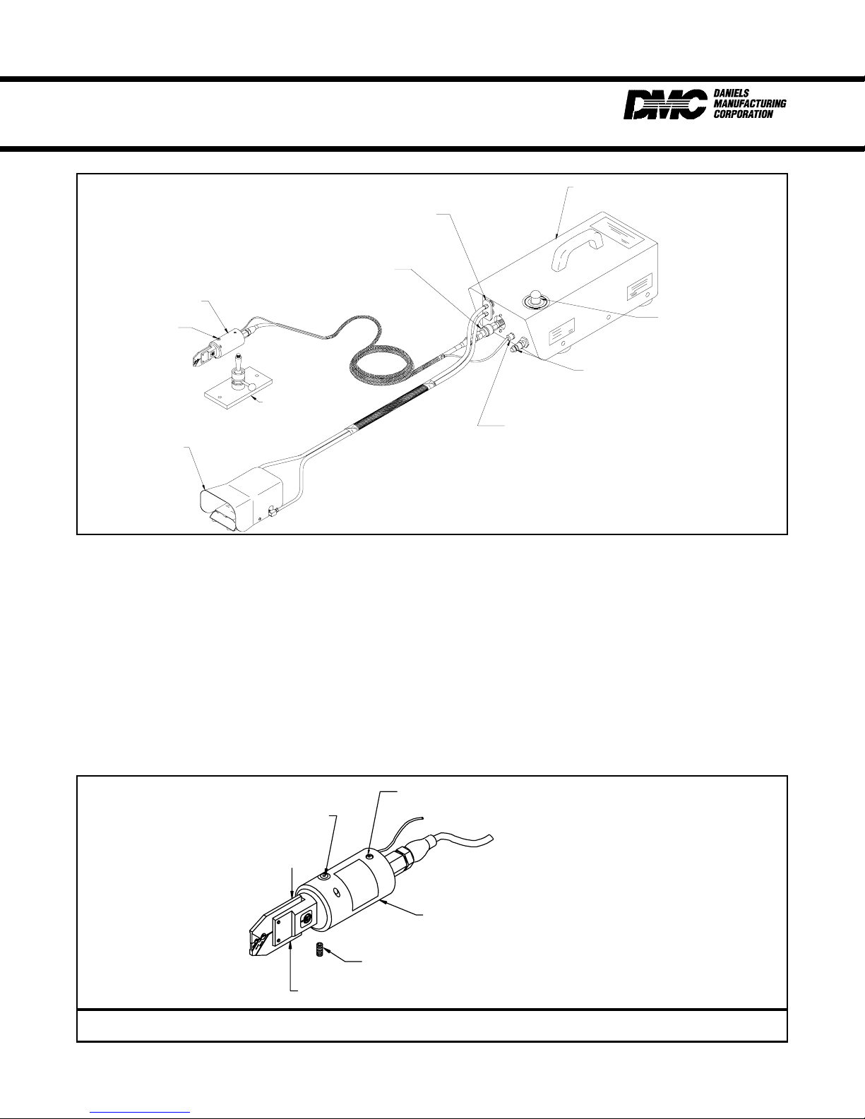
The PH1005 Power Crimp Toolconsists of the PHMT1005 CrimpingTool, PHRPU4 Remote Power Unit, PHFV3 Foot Press (optional), and the BM-2 Bench Mount (optional). Four features used for operation or control can be
seen on the front panel of the PHRPU4 Remote Power Unit, they include the Hydraulic Quick Disconnect, Dual
Coupling Control, Single Coupling Control, and the Input Air Quick Disconnect. Use the following steps to assemble the separate parts:
1. Connectthe hydraulic hose from the PHMT1005 Crimping Tool into the hydraulic quick disconnect on thefront
panelof the PHRPU4 Remote Power Unit by pushing back on the lockingringofthehydraulic quick disconnect
andpluggingthe male part of the hydraulic hose into the provided area. Theoperator will realize the connection
has been made when the locking ring snaps into place.
2. Connect the small tool control hose from the PHMT1005 Crimping Tool to the single coupling control on the
front panel of the PHRPU4 Remote Power Unit by pushing the connecting end of hose into the fitting until the
spring clip locks into place.
3. Connecttheshop air supply to the air quick disconnect by pulling back on the air hose coupling and inserting the
hose into the fitting on the PHRPU4 Remote Power Unit.
4. If PHFV-3 Foot Press is supplied, connect it to the dual coupling control by orienting the connector on the hose
so the side marked "TOP" is up, then press inward until the spring clips lock into place.
5. IfBM-2 Bench Mount is supplied, attach ittothe PHMT1005 Crimping Tool by threading themalethreadof the
benchmount into the female thread on the tool. Adjust toolto appropriate working position, and lock handle on
bench mount.
EMERGENCY STOP BUTTON
ThePHRPU4 Remote Power Unit is configured with an Emergency Stop Button. Bypressingthisbuttonat any time
during the crimp cycle, the forward motion on the crimp tool will stop and retract to the open position. Further
operation of the system will be inhibited until this Emergency Stop Button is rotated in a clockwise direction and
DANIELS MANUFACTURINGCORP. 526 THORPEROAD, ORLANDO, FL 32824, USA
PHONE (407)855-6161 • FAX (407) 855-6884• WWW.DMCTOOLS.COM • E-MAIL: [email protected]
COPYRIGHT© 2001 ALL RIGHTS RESERVED
1of6
12/01 REV. A FILE #: SOM0021 DOC. #: PH1005-SOM
Page 2
PHMT1005
AIR BLEED
(ACTUATOR)
PHFV-3
(OPTIONAL)
DUAL COUPLING CONTROL
HYDRAULIC QUICK
DISCONNECT
BM-2
(OPTIONAL)
FIGURE 1
SAFETY OPERATION MANUAL
PHRPU4
EMERGENCY STOP
BUTTON
INPUT AIR
QUICK DISCONNECT
SINGLE COUPLING CONTROL
allowed to release.
Tool Head Positioning (see Figure 2):
Thetoolheadon the PH1005 Crimping Tool may be rotated to any selectable position relative to the actuator that an
operatormightprefer. Toselect or change the head position, loosenthe headposition holding screwso thehead can
be turned by hand and rotate head to selected position, then tighten screw.
TOOL OPERATION:
After the PH1005 tool has beenassembled with the dies intheir proper location, the tool isready for operation. Use
the following steps to operate the tool properly and safely:
1. Connect the PHRPU4 remote power unit to a standard shop air supply of 80 - 120 psi. (5.5 - 8.3 BAR).
2. Insert component to be crimped in crimp jaws and position properly. The jaws are spring loaded and will hold
the part in place.
HYDRAULIC FLUID
AIR BLEED HOLE (SEAL HOLE
WITH FINGER TO ACTIVATE
TOOL)
FIGURE 2
PRESS HERE TO LOAD AND UNLOAD SPLICE
FILL HOLE
PHMT1005
CRIMP TOOL
HEAD POSITIONING HOLDING SCREW
DANIELS MANUFACTURING CORP. 526 THORPE ROAD, ORLANDO, FL 32824, USA
PHONE (407) 855-6161 • FAX (407) 855-6884 • WWW.DMCTOOLS.COM • E-MAIL: [email protected]
2of6
12/01 REV. A FILE #: SOM0021 DOC. #: PH1005-SOMCOPYRIGHT© 2001 ALL RIGHTS RESERVED
Page 3
SAFETY OPERATION MANUAL
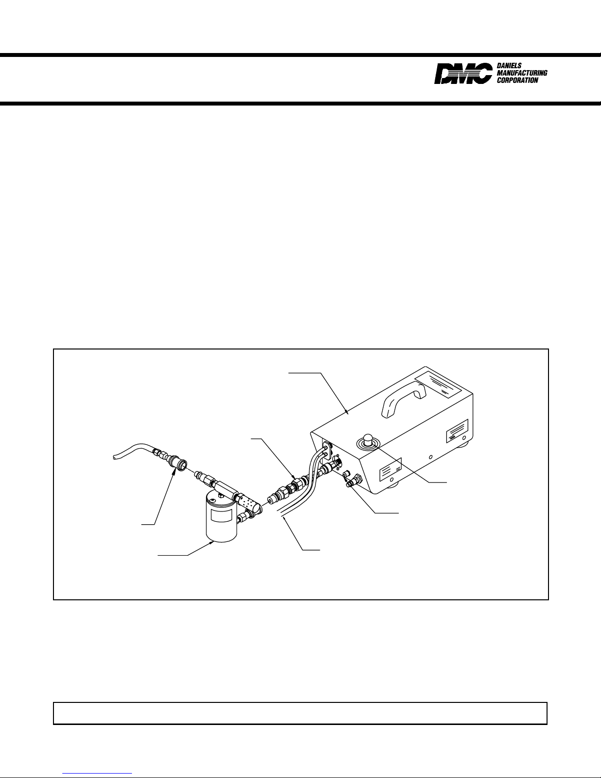
3. Cover the air bleed (actuator) of the tool and start the crimp cycle (see Figure 3).
4. If the Foot Press (PHFV-3) is used, a momentary press will start the crimp cycle.
NOTE: Should the tool not complete its cycle and open, check the supply air pressure. If the pressure reads
below 80 psi(5.5 BAR), bring it back up to a minimum of 80 psi. If the pressure is adequate, push
the Emergency Stop Button on the top of the PHRPU4 Remote Power Unit in order to open the tool.
It will be necessary to check fluid level as indicated in the next section. Do not use the tool for
crimping until this default condition has been corrected.
HYDRAULIC FLUID REFILL:
Use the following procedure to replace lost system hydraulic fluid:
PHVG VACUUM GENERATOR (see Figure 3): The PHVG vacuum generator is used with the various PH
series systems for the removal of any air that might be present in the hydraulic hose or in the PHRPU4 intensifier, and the replacement of any fluid loss from leakage or evaporation.
Procedure: It is necessary to use the vacuum generator with an amount of hydraulic fluid in the bottom of the
fill bowl. Remove the two screws that hold the cover of the bowl and pull it open. With the bowl sitting flat,
PHRPU4 REMOTE POWER UNIT
PHVG CONNECTION
(ADAPTOR)
EMERGENCY STOP
BUTTON
SINGLE COUPLING CONTROL
AIR SUPPLY
PHVG HYDRAULIC
FILL BOWL
TO PHFV-3 FOOT PRESS
FIGURE 3
coverthe bottom with about 1/4" of ISO46AW hydraulic fluid. Reassemblecover, align holes and tighten down
with the two screws just removed.
Recharging tools: Plug the male coupling of the tool hose into the female quick disconnect coupling on the
PHVG vacuum generator by pulling lock ring back while pushing the male plug in place. The lock ring will
snap back in place when released and the male plug is seated. Making sure the fill bowl is level so oil in the
bowlcoverstheinputfromthebottomofthebowl,plugintheairsupplyto the fitting provided on the rear of the
DANIELS MANUFACTURING CORP. 526 THORPE ROAD, ORLANDO, FL 32824, USA
PHONE (407) 855-6161 • FAX (407) 855-6884 • WWW.DMCTOOLS.COM • E-MAIL: [email protected]
COPYRIGHT© 2001 ALL RIGHTS RESERVED
3of6
12/01 REV. A FILE #: SOM0021 DOC. #: PH1005-SOM
Page 4
SAFETY OPERATION MANUAL
vacuum generator. As a vacuum is formed, air bubbles will pull through the oil in the bowl and the fluid level
willrise slightly. Continueto allow thevacuumgenerator to "run" until there are no noticeablebubbles flowing
through the system, or the flow of bubbles is at minimum. Unplug the air supply slowly and watch as the level
offluid in the bowl lowers. After waiting about five seconds,thetoolhose can be disconnected from thesystem.
Recharging the PHRPU4: It is necessary to plug the adaptor into the vacuum generator and into the PHRPU4
Remote Power Unit. Holding the fill bowl level with the PHRPU4 sitting on its four feet, plug the air supply
into the vacuum generator. Run the unit until there are no air bubbles or they are minimal, then slowly unplug
theairsupply.Whentheoillevelnolonger lowers (about five seconds) the generator/adaptor may be uncoupled
from the PHRPU4 Remote Power Unit and the tool hose reconnected. If a system default occurs whereby a tool
closes and will not open without activating the Emergency Stop Button and the air supply is proper (80 psi./5.5
BAR), charge both the tool and the PHRPU4 to correct the fault. If recharging does not correct the default
condition and the air supply is proper, return the system to DMC for service. It is recommended that a peri-
odic schedule be maintained for charging the system.Iffluid, other than small amounts, are displaced during
the system charging, the schedule should be changed to charge more frequently. If heavy leakage is noted and
daily charging is required, the tool/PHRPU4 system should be returned to DMC for seal replacement. It should
be noted that small amounts of fluid will be present at the coupling during the charging of the system or when
tools are disconnected from the PHRPU4.
OPERATIONALCHARACTERISTICS:
The PH1005 Power Crimp Tool builds up substantial internal hydraulic pressures in attaining the resultant crimp
force. This may result in some leakage of hydraulic fluid past the seals in the tool. This does not mean the tools
cannot be used. As long as the tools close properly, they will provide an adequate crimp. Add hydraulic fluid as
necessary. Where the fluid leakage has become unacceptable, please contact the DMC factory for the proper procedure to return the tool for seal replacement.
GAGING PROCEDURES:
Periodic gaging is suggested to monitor and assure that the proper crimp is being generated in the crimp
area.
CAUTION: DO NOT CRIMP GAGE!
"Go" Gaging
With the crimp jaws in fully closed position, insert"Go" gageend intoappropriate cavity. Gage must pass
freely through crimping cavity.
"No-Go" Gaging
With the crimp jaws in fully closed position, attempt to insert "No-Go" gage end into the appropriate
cavity. Gage may partially enter, but must not pass completely through the cavity.
DANIELS MANUFACTURING CORP. 526 THORPE ROAD, ORLANDO, FL 32824, USA
PHONE (407) 855-6161 • FAX (407) 855-6884 • WWW.DMCTOOLS.COM • E-MAIL: [email protected]
4of6
12/01 REV. A FILE #: SOM0021 DOC. #: PH1005-SOMCOPYRIGHT© 2001 ALL RIGHTS RESERVED
Page 5
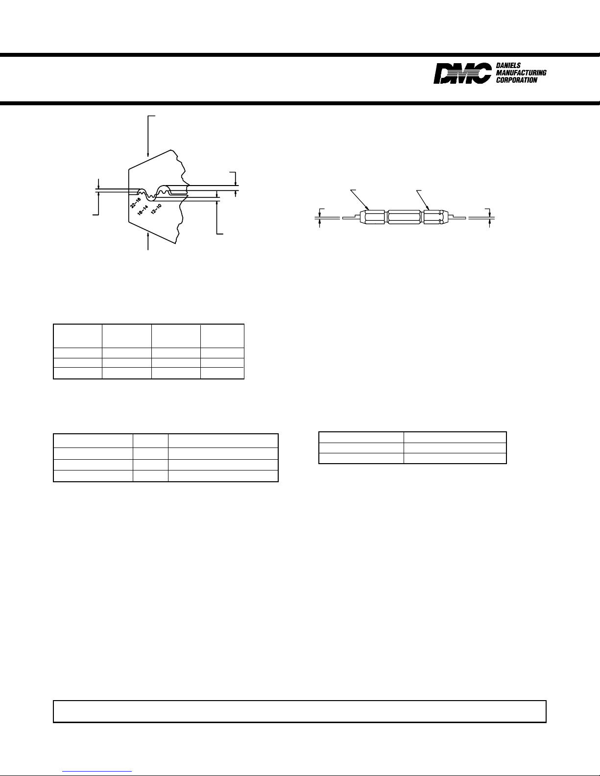
WHEN CHECKING GAGING
DIMENSIONS, HOLD JAWS
TOGETHER TO INSURE A
FULLY CLOSED POSITION.
.079
±.003
SAFETY OPERATION MANUAL
GREEN "GO"
RED "NO-GO"
.049
±.003
.057
±.003
FIGURE 4
GAGING DIMENSIONS FOR PH1005:
CRIMP
CAVITY
22-16
16-14
12-10
"GO"
DIM A
.046
.054
.076
PH1005 SYSTEM COMPONENTS:
PART NUMBER
PHMT1005
PHRPU4
PHVG
"NO-GO"
QTY
1
1
1
DIM B
.052
.060
.082
DESCRIPTION
CRIMPING TOOL
REMOTE POWER UNIT
VACUUM GENERATOR
GAGE
P/N
G739
G740
G741
A
GAGE
B
FIGURE 5
POWER TOOL SYSTEM ACCESSORIES:
PART NUMBER
BM-2
PHFV-3
DESCRIPTION
BENCH MOUNT
FOOT PRESS
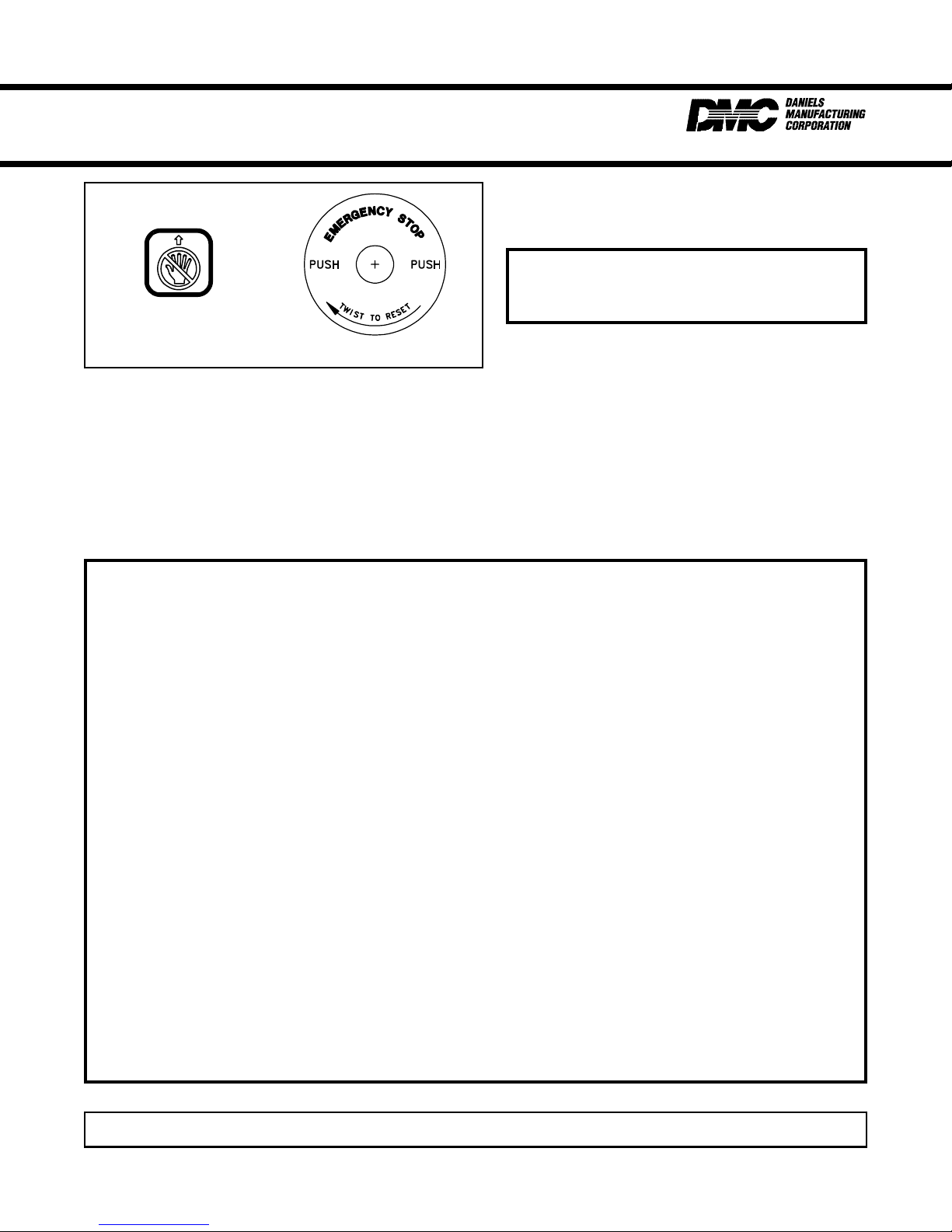
SAFETY SIGNAGE
Safety signs are placed on the PH1005 Power Crimp Tool to make you aware that this tool could seriously injure or
maim you if care is not used while operating it.
Thesesignsareintended as a constant reminder of the potential risk involved. Thesesigns should never beremoved
and should be replaced as needed.
Signs alone will not prevent accidents from occurring. Operators must be properly trained in the use of the equipment and be aware of the risks involved. While using the tool, it is important to be alert and avoid distractions.
DANIELS MANUFACTURING CORP. 526 THORPE ROAD, ORLANDO, FL 32824, USA
PHONE (407) 855-6161 • FAX (407) 855-6884 • WWW.DMCTOOLS.COM • E-MAIL: [email protected]
COPYRIGHT© 2001 ALL RIGHTS RESERVED
5of6
12/01 REV. A FILE #: SOM0021 DOC. #: PH1005-SOM
Page 6
SAFETY OPERATION MANUAL
DISCONNECT FRDISCONNECT FR
DISCONNECT FR
DISCONNECT FRDISCONNECT FR
BEFOREBEFORE
BEFORE
BEFOREBEFORE
TT
OOL OR DIESOOL OR DIES
T
OOL OR DIES
TT
OOL OR DIESOOL OR DIES
AA
TTEMPTINGTTEMPTING
A
TTEMPTING
AA
TTEMPTINGTTEMPTING
OMOM
AIR SUPPLAIR SUPPL
OM
AIR SUPPL
OMOM
AIR SUPPLAIR SUPPL
TT
OO
ADJUSTADJUST
T
O
ADJUST
TT
OO
ADJUSTADJUST
..
.
..
YY
Y
YY
FINGER FREE AREAS
EMERGENCY STOP
Daniels Manufacturing Corporation offers complete refurbishing and recalibration services.
DMC specially engineers and manufactures complete tool kits to satisfy individual customer requirements, such as
total aircraft support, general shop maintenance or production, on board ship and vehicle service, etc.
LIMITATION OF LIABILITY/LIMITED WARRANTY*
DMC (DANIELS MANUFACTURING CORP.) IS NOT LIABLE FOR CONSEQUENTIAL
ORSPECIAL DAMAGESOF ANY NATURE OR KIND RESULTING FROM THE USE,OR MISUSE,OF
ANY OF ITS PRODUCTS. OWNERS AND USERS OF DMC PRODUCTS ASSUME FULL RESPONSIBILITY FOR INSTRUCTING OPERATORS IN THE PROPER AND SAFE USE OF SUCH PRODUCTS.
OPERATORSASSUME FULLRESPONSIBILITYFOR OPERATING DMCPRODUCTSIN ASAFEMANNER AND ACCORDING TO DMC OPERATING INSTRUCTIONS.
DMC (Daniels Manufacturing Corp.) warrants each new product sold by it to be free from defects in
materialand workmanship under normal use and service. DMC'sobligation under this warranty is limitedtothe
freecorrectionor, at DMC's option, the refund of the purchase price of any suchproduct whichproves defective
in normal service within ninety (90) days after delivery to the first user, provided that the product is returned to
DMCwithalltransportationchargesprepaid and which shall appear to DMC's satisfaction, after DMC's inspection, to have been defective in material or workmanship, it being understood that DMC products are not consumer products. This warranty shall not cover any damage to any product which, in the opinion of DMC, was
caused by normal wear, misuse, improper operation, tampering, neglect or accident.
This limited warranty is in lieu of all other warranties express or implied, including, but not limited to,
warranties of fitness for aparticular purpose and warranties ofsafe operation. No warranty, express or implied,
is made or authorized to be made or assumed with respect to products of Daniels Manufacturing Corporation,
other than that herein set forth.
*as defined by PL93-637
DANIELS MANUFACTURING CORP. 526 THORPE ROAD, ORLANDO, FL 32824, USA
PHONE (407) 855-6161 • FAX (407) 855-6884 • WWW.DMCTOOLS.COM • E-MAIL: [email protected]
6of6
12/01 REV. A FILE #: SOM0021 DOC. #: PH1005-SOMCOPYRIGHT© 2001 ALL RIGHTS RESERVED
 Loading...