

Page 1
Analog Resistive Touchscreen
ATP/AST Series Product Specifications
Page 2
ATP/AST Series Product Specifications
Table of Contents
1. Product Specifications ...................................................................................................................... 3
1-1. Product Applicable ........................................................................................................................ 3
1-2. Structure ...................................................................................................................................... 3
1-3. Environmental Specifications......................................................................................................... 3
1-4. Mechanical Characteristics ........................................................................................................... 3
1-5. Electrical Characteristics ................................................................................................ ............... 3
1-6. Appearance .................................................................................................................................. 4
2. Testing Regulation ............................................................................................................................ 5
2-1. Testing Regulation ........................................................................................................................ 5
2-2. Environmental Specifications......................................................................................................... 5
2-3. Mechanical Characteristics ........................................................................................................... 5
2-4. Electrical Characteristics ................................................................................................ ............... 6
2-5. Appearance .................................................................................................................................. 6
3. Reliability Condition .......................................................................................................................... 7
3-1. Temperature Condition .................................................................................................................. 7
4. Recommended Connector ................................................................................................................ 7
4-1. Recommended Connector ............................................................................................................ 7
5. Handling Notes.................................................................................................................................. 8
5-1. Precautions .................................................................................................................................. 8
5-2. Handling Notes ............................................................................................................................. 8
5-3. Construction Notes ....................................................................................................................... 8
5-4. Electrical & Software Notice .......................................................................................................... 8
5-5. Mounting Notes ............................................................................................................................ 9
6. Warranty .......................................................................................................................................... 10
6-1. Warranty Period .......................................................................................................................... 10
6-2. Warranty Target .......................................................................................................................... 10
6-3. Warranty Exceptions ................................................................................................................... 10
6-4. Tools .......................................................................................................................................... 10
6-5. Changes .................................................................................................................................... 10
6-6. RoHS Compliance……………………………......................................................................................11
7. Revision History .............................................................................................................................. 11
DER-S0087A 2 Rev. 13©1999 - 2013 DMC Co., Ltd.
Page 3
ATP/AST Series Product Specifications
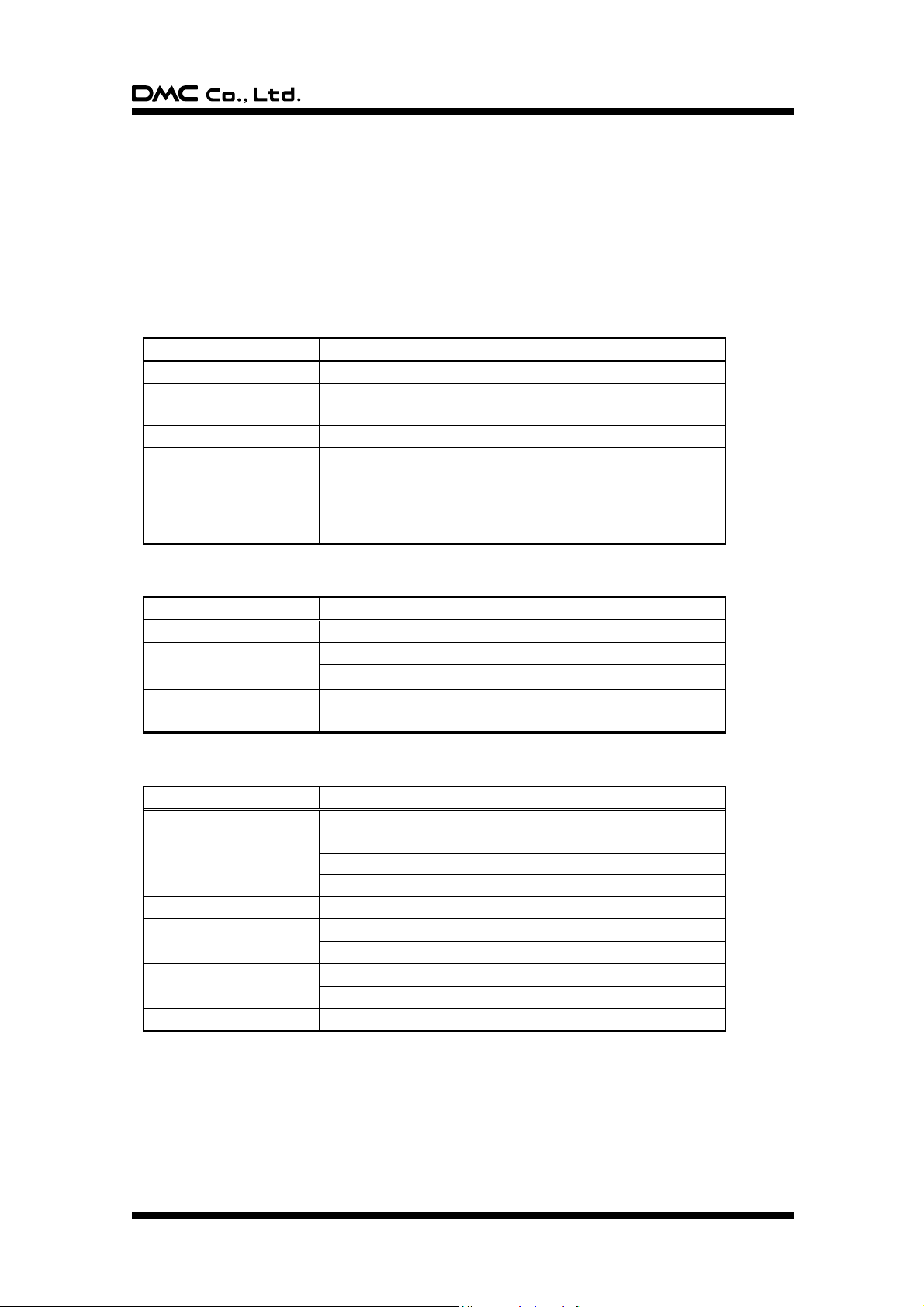
Specification
Value
Operating Temperature
-20°C to 70°C (no condensation)
Operating Humidity
-20°C to 60°C Less than 90%RH (no condensation)
Exceeding 60°C 133.8g/m3 (no condensation)
Storage Temperature
-40°C to 80°C (no condensation)
Storage Humidity
-40°C to 60°C Less than 95%RH (no condensation)
Exceeding 60°C 142.9g/m3 (no condensation)
Chemical Resistance
(top surface)
Toluene, Tricholoroethylene, Athetone, Alcohol,
Gasoline, Machine Oil, Ammonia, Glass Cleaner,
Mayonnaise, Ketchup, Wine, Salad Oil, Vinegar, Lipstick, etc.
Specification
Value
Activation Force
0.05N to 0.8N
Operating Life
Input (finger)
10,000,000 hits
Character Input (pen)
100,000 characters
Light Transmittance
Over 80% (typical value at full wavelength)
Surface Hardness
Over 2H (by JIS pencil hardness)
Specification
Value
Maximum Voltage
DC6V
Maximum Current
Top Electrode
100mA
Bottom Electrode
100mA
Between the Top and Bottom
0.5mA
Linearity
Under 2Under 1% (typical value))
Terminal Resistance
Top Electrode
Less than 1k
Bottom Electrode
Less than 1k
Insulation Resistance
Neighboring Terminals
Over 20M at 25V
Active Area Electrodes
Over 20M at 25V
Chattering
Less than 10msec at ON/OFF.
1. Product Specifications
1-1. Product Applicable
§ This specification is applied to the analog resistive touchscreen: ATP/AST Series.
1-2. Structure
§ Dimensions, structure, and shape are referred on the drawing attached.
1-3. Environmental Specifications
1-4. Mechanical Characteristics
1-5. Electrical Characteristics
DER-S0087A 3 Rev. 13©1999 - 2013 DMC Co., Ltd.
Page 4
ATP/AST Series Product Specifications
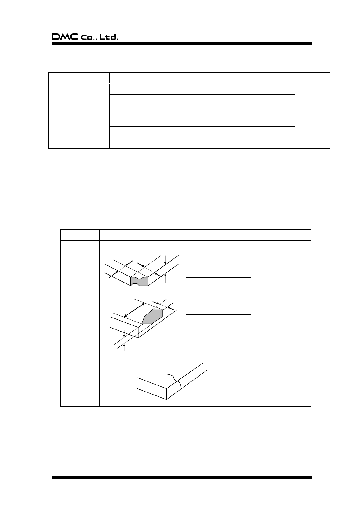
Item
Width (mm)
Length (mm)
Acceptable Numbers
Total
Linear(Scratch/Dust)
Over 0.1mm in
diameter refer to the
Circular.
0.1W>0.05
4L
1pcs in 30mm
Within 5pcs
/panel
0.05W>0.03
10L
2pcs in 20mm
0.03W
20L
Acceptable
Circular
(Scratch/Dust)
0.4D>0.3 *1
1pcs in viewing area *1
0.3D>0.2
2pcs in 30mm
0.2D
Acceptable
Item
Size (mm)
Acceptable Numbers
Corner
X
3
2pcs
/panel
Y
3 Z t
Side
X
5
2pcs
/side
Y
3 Z t
Crack
Not acceptable
X Y Z
Z
X
Y
1-6. Appearance
§ Scratch, dust (W = width, L = length, D = average diameter = (longest + shortest) /2)
Applied only in the Active Area. Scratches or dusts in the outside of the Active Area are acceptable unless the
electrical characteristics are affected.
*1 Applied to the size of 14 inches or more.
§ Dirt
Acceptable if not noticeable on a black mat.
§ Chip, crack (t = glass thickness) (applicable only for the glass)
DER-S0087A 4 Rev. 13©1999 - 2013 DMC Co., Ltd.
Page 5
ATP/AST Series Product Specifications
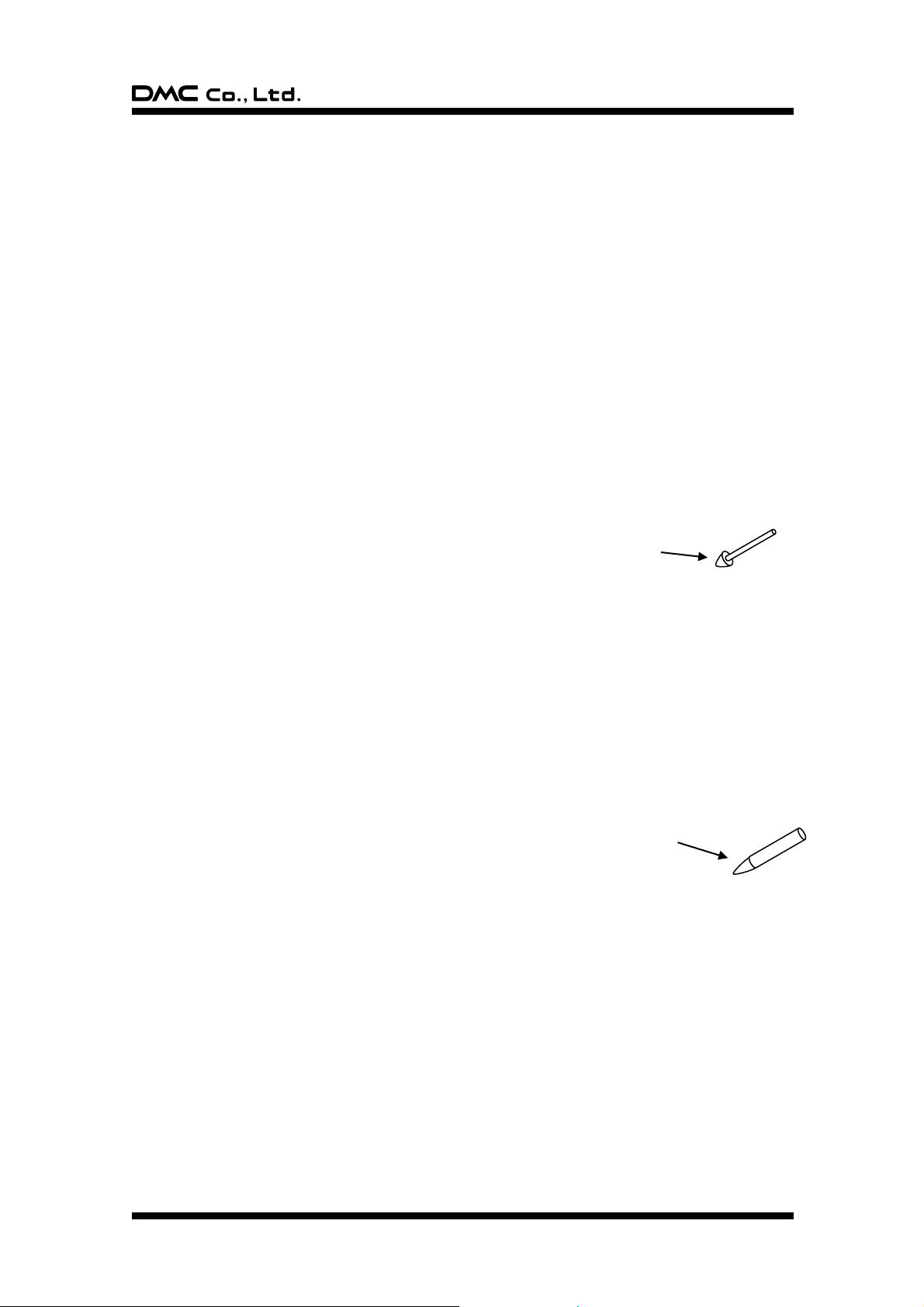
Polyacetal resin
Tip: R = 0.8
Figure 2. Testing rod 2
Silicon Rubber
(Hardness: 60°)
Tip: R = 4.0
Figure 1. Testing rod 1
2. Testing Regulation
2-1. Testing Regulation
§ If the regulation is not specified, the test is performed under the supplier’s regulation.
§ Tests are performed under the room temperature unless specified. The room temperature is referred as
follows:
Temperature: 20C5C
Humidity: 65%10%RH
2-2. Environmental Specifications
§ Chemical Resistance Test
Condition: Tested after leaving the chemical on the surface for 12 hours being wiped off by cloth.
Judgement: Must be no effect in appearance.
2-3. Mechanical Characteristics
§ Activation Force Test
Condition: Measured by depressing the point between
the dots to the conduction by the testing rod
(Figure 1).
Judgement: Must satisfy the specification.
§ Operating Life Test (Finger)
Condition: Testing rod: Refer to Figure 1
Voltage: DC5V
Load: 3N
Cycle: 2 hits/sec
Judgement: Must satisfy the following:
Activation Force: Must satisfy the specification.
Linearity: Must satisfy the specification.
Terminal Resistance: Must satisfy the specification.
Insulation Resistance: Must satisfy the specification.
§ Operating Life Test (Pen)
Condition: Testing rod: Refer to Figure 2
Voltage: DC5V
Load: 2.5N
Input size: 10 x 10 mm
Input character: A to Z/minute
Judgement: Must satisfy the following:
Activation Force: Must satisfy the specification.
Linearity: Must satisfy the specification.
Terminal Resistance: Must satisfy the specification.
Insulation Resistance: Must satisfy the specification.
DER-S0087A 5 Rev. 13©1999 - 2013 DMC Co., Ltd.
Page 6
ATP/AST Series Product Specifications
2-4. Electrical Characteristics
§ Terminal Resistance Test
Condition: Top and bottom electrodes are measured at the terminal.
Judgement: Must satisfy the specification.
§ Insulation Resistance Test
Neighboring Terminals: Measured by applying the reference voltage to the terminals
Active Area Electrodes: Measured by applying the reference voltage to the top and bottom electrodes.
Judgement: Must satisfy the specification.
2-5. Appearance
§ Appearance Test
Condition: Tested by an examiner with over 1.0 eyesight at 30cm away from the product under the
transmittable light at over 60° the surface of the product.
Judgement: Must satisfy the specification.
DER-S0087A 6 Rev. 13©1999 - 2013 DMC Co., Ltd.
Page 7
ATP/AST Series Product Specifications
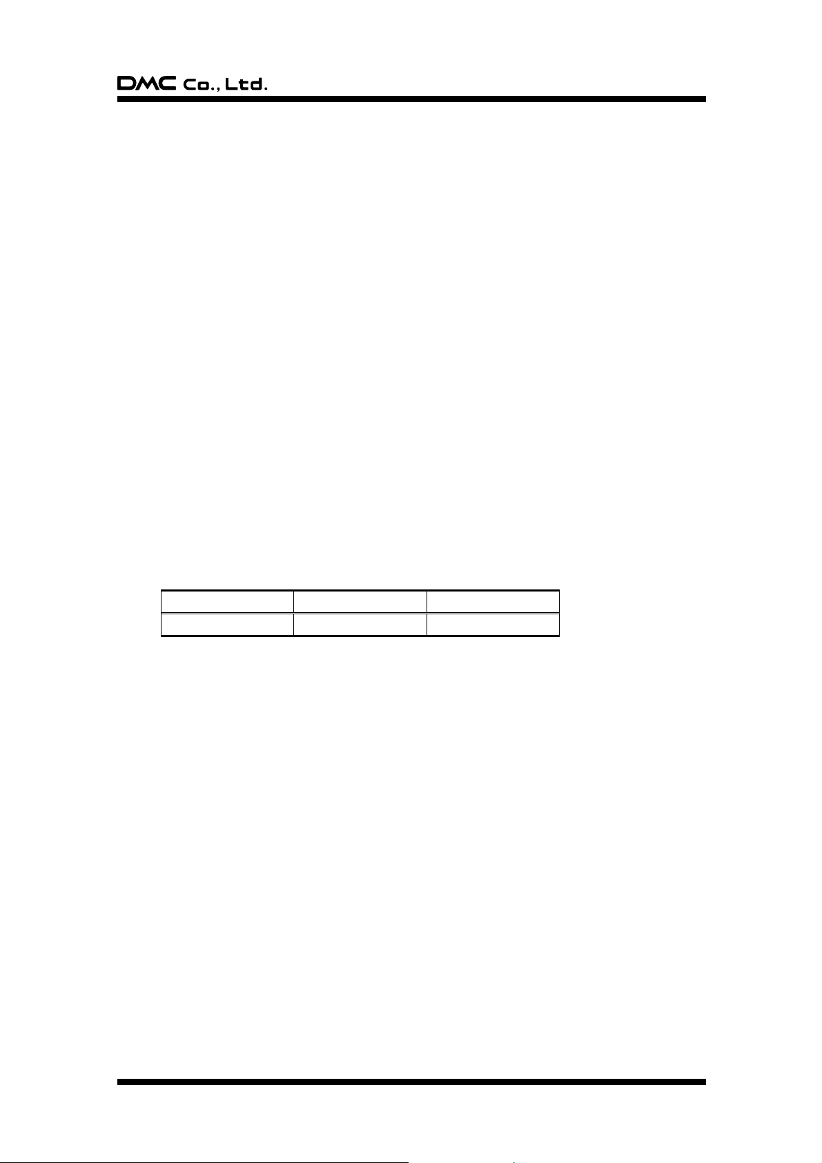
Part No.
Pins
Pitch
KCA-K4R
4 pin Double-sided
1.25mm
3. Reliability Condition
3-1. Temperature Condition
§ Temperature Condition Test
Following test are performed in the condition with no dew condensation:
Cold Test: Tested after leaving the parts in -40°C3°C for 240 hours and in the room temperature
for 2 hours.
Heat Test: Tested after leaving the parts in 80°C3°C for 240 hours and in the room temperature for
2 hours.
Humidity Test: Tested after leaving the parts in the temperature 60°C3°C, humidity 90 to 95% for 240
hours and in the room temperature for 2 hours.
Cycle Test: Tested after 5 cycles of leaving the parts in the temperature -30°C3°C for 1 hour and in
the room temperature for 0.5 hours, then leaving the parts in the temperature 70°C3°C
for 1 hour and in the room temperature for 0.5 hours.
Judgement: Must satisfy the following:
Activation Force: Must satisfy the specification.
Linearity: Must satisfy the specification.
Terminal Resistance: Must satisfy the specification.
Insulation Resistance: Must satisfy the specification.
Appearance: Must satisfy the specification.
4. Recommended Connector
4-1. Recommended Connector
DER-S0087A 7 Rev. 13©1999 - 2013 DMC Co., Ltd.
Page 8
ATP/AST Series Product Specifications
5. Handling Notes
5-1. Precautions
§ This product is intended for use in standard applications (computers, office automation, and other office
equipment, industrial, communications, and measurement equipment, personal and household devices,
etc.) Please avoid using this product for special applications where failure or abnormal operation may
directly affect human lives, or cause physical injury or property damage, or where extremely high levels
of reliability are required (such as aerospace systems, vehicle operating control, atomic energy controls,
medical devices for life support, etc.).
5-2. Handling Notes
§ Do not depress or scratch the product with any object with a sharp edge or hard end.
§ Do not put this product close to fire.
§ Do not wipe this product with too much load.
§ Do not strongly rub this product locally. It may affect the product’s functions.
§ Do not hit the product with a hard object.
§ Do not forcibly bend or fold the product.
§ When the product is stored, make sure it is packed in a packing box and stored in a storage temperature
range, eliminating any outside load.
§ Do not use or store the product under a condition where the product will be exposed to water, organic
solution or acid.
§ Do not use the product under the direct sunlight.
§ Do not disassemble the product.
§ When you handle the product, Hold the product by its body. Do not hold by the tail.
§ Clean the product with a soft cloth or a soft cloth with neutral detergent or alcohol. When contaminated
by chemicals, wipe them off immediately with caution not to cause injury to human body.
§ The edge of the glass is not rounded and may cause injury.
5-3. Construction Notes
§ The environmental specifications, mechanical characteristics, and electrical characteristics are only
applied to the Active Area.
§ Do not use the touchscreen when the condensation occurs. The condensation inside of the touchscreen
is a natural phenomenon and should disappear after the touchscreen is warmed up.
5-4. Electrical & Software Notice
The best performance can be obtained when used with the original analog resistive touchscreen controller,
“TSC-10” Series. If the touchscreen controller or controller software is to be developed by the customer,
please note the following:
§ There is a contact resistance between the top and bottom electrodes and it changes by the pressure of a
finger or a pen. The data must be read after the contact resistance becomes stabilized.
§ The terminal resistance of the analog resistive touchscreen varies by the individual, time, and
environment. The controller software must have the calibration function to adjust the input position and
the display position.
§ The analog resistive touchscreen outputs 2 point input as 1 point in between the 2 points. The controller
software must not be designed to have the 2 point input function.
§ For drawing applications, the line may be intermittent when the pen comes on the dot spacers. A
software compensation is needed.
DER-S0087A 8 Rev. 13©1999 - 2013 DMC Co., Ltd.
Page 9
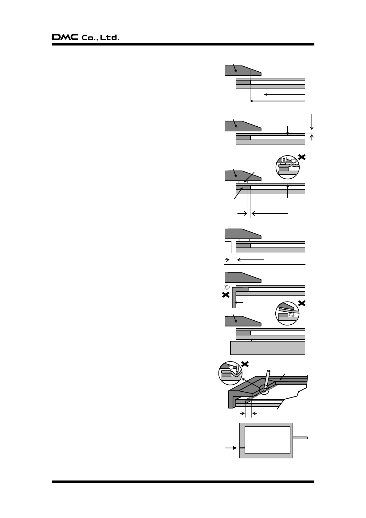
ATP/AST Series Product Specifications
0.5mm
Top Electrode
Bezel
Bezel
Display
Forbidden Area
Bezel
Bezel
Active Area
Viewing Area
Tail
0.2 - 0.3mm
Case
Top Electrode
Bezel
Cushion
Insulation Area
Minimum 1mm
5-5. Mounting Notes
§ Bezel Edge
Bezel edge must be positioned in the area between the Active
Area and the Viewing Area. The bezel may press the
touchscreen and cause input if the edge enters the Active
Area.
§ Gap between the Bezel and Touchscreen
A gap of approximately 0.5mm is needed between the bezel
and the top electrode. It may cause unexpected input if the
gap is too narrow.
§ Cushion
If a cushion is used between the bezel and the top electrode,
the cushion must be free enough to absorb the expansion and
contraction difference between the bezel and the top
electrode. If the cushion is squashed too hard, the expansion
and the contraction difference may cause the distortion to the
top electrode.
The cushion must be positioned more than 1mm outward from
an inside of the insulation area. (Please refer to right figure)
§ Tolerance
There is a tolerance of 0.2 to 0.3mm for the dimensions of the
touchscreen and the tail. A gap must be made to absorb the
tolerance in the case and the connector.
§ Tail
The tail must not be forcibly stressed or bent too hard to avoid
the conduction in the insulated area and wire breaking.
§ Mounting
Touchscreen must be held from the bottom such as the
structure gluing the touchscreen onto the display. If the
touchscreen is glued to the bezel, the adhesion between the
top and bottom electrode is stressed and may come off.
§ Forbidden Area
The area within 2mm from the insulation area is structurally
week for the pressure, espcially for pen use. The film may be
forcibly bent and may cause defection. This area must be
protected by the bezel and input must be avoided.
§ Air Vent
Most of the touchscreens have the air vent to equalize the
inside air pressure to the outside one. The air vent must be
open and liquid contact must be avoided as the liquid may be
absorbed if the lquid is accumilated near the air vent. The top
electlode must not be swelled by the air pressure from inside
of the case.
DER-S0087A 9 Rev. 13©1999 - 2013 DMC Co., Ltd.
Page 10
ATP/AST Series Product Specifications
6. Warranty
6-1. Warranty Period
§ The warranty period is limited to 1 year from the date of shipping. The warranty for the initial defection
such as appearance defection is limited to 1 month.
§ Any defected parts under proper use will be examined by the supplier and replaced by the new parts if
the defection is considered to be caused by the supplier.
§ The replacement is subject to be included in the next lot.
6-2. Warranty Target
§ The warranty only covers the product itself and does not cover any damage to others caused by using
this product. Onsite repair or replacement is not supported.
§ We will do our best for delivery problem and product defections, but the warranty for the production line
is not covered.
§ Resistive touchscreens are structurally not repairable. All defections are subject to replacement.
6-3. Warranty Exceptions
Following conditions are not covered with the warranty and subject to charge.
§ Any malfunctions and damages during transportation and transfer by the user.
§ Any malfunctions and damages caused by a natural disaster or a fire.
§ Any malfunctions and damages caused by static electricity
§ Any malfunctions and damages caused by the failure of the associated equipment.
§ If the product is remodeled, disassembled or repaired by the user.
§ If the product is glued onto the equipment and uninstalled.
§ Any malfunctions and damages caused by an improper usage and handling against the specifications
and notes.
6-4. Tools
§ All the tools, such as CAD data (except for the drawing for approval), block copies (films), printing
screens, and die-cut plates are not to be provided for administrative purpose.
6-5. Changes
§ Because of the manufacturing process, changing the dimensions, circuit pattern, and the tail position
requires replacing most of the tools and is subject to high tooling charge. Please be careful when
ordering and approving the drawing.
§ Circuit pattern and the materials that does not affect the environmental, electrical, and mechanical
characteristics such as film, glass, ink and glue are subject to change for the supplier’s reason or for
improvement within the specifications.
§ Standard products are subject to change for improvement without notice.
6-6 RoHS Compliance
§ This product complies with RoHS
DER-S0087A 10 Rev. 13©1999 - 2013 DMC Co., Ltd.
Page 11
ATP/AST Series Product Specifications
7. Revision History
Rev1 (April 15, 1998)
Initial release
Rev2 (June 1, 1999)
The overall revision by specification review.
Rev3 (April 1, 2002)
The address in the office was changed by the move.
Rev4 (August 16, 2002)
1-4.Activation Force is changed “50g 30g” to “0.5N0.3”.
1-4.Light Transmission is changed 76% to 80%(TYP).
Rev5 (September 3, 2002)
1-3.Operating Temperature is changed “0°C to 60°C” to “-20°C to 70°C”.
1-3.Storing Temperature is changed “-20°C to 70°C” to “-40°C to 80°C”
1-4.Operating Life is changed “1,000,000 hits” to “10,000,000 hits”.
1-5.Linearity is changed “Under 2” to “Under 1% (typical value)”.
Rev6 (June 28, 2004)
1-3.Operating Humidity is changed “Less than 90%RH (no condensation)” to “-20°C to 60°C Less than
90%RH (no condensation) Exceeding 60°C 133.8g/m3 (no condensation)”.
1-3.Storing Humidity is changed “Less than 95%RH (no condensation)” to “-40°C to 60°C Less than
95%RH (no condensation), Exceeding 60°C 142.9g/m3 (no condensation)”.
1-5.Maximum Voltage is changed “DC5V” to “DC6V”.
1-5.Linearity is changed “Under 1% (typical value)” to “Under 2Under 1% (typical value))”.
Rev7 (October 15, 2004)
4-4.Electrical & Software Notice: Changed “FIT-10 series” to “TSC-10 series”.
Rev8 (April 7, 2005)
Added Item4 Recommended Connector.
Rev9 (September 6, 2005)
2-3.Mechanical Characteristics: Added Operating Life Test (Pen).
DER-S0087A 11 Rev. 13©1999 - 2013 DMC Co., Ltd.
Page 12
ATP/AST Series Product Specifications
Rev10 (November 10, 2006)
The specification item name was changed.
1-3.”Storing Temperature” to “Storage Temperature”
1-3.”Storing Humidity” to “Storage Humidity”
1-4.”Operating Load” to “Activation Force”
1-4.”Light Transmissivity” to “Light Transmittance”
1-4.”Top Surface Hardness” to “Surface Hardness”
2-3.”Operating Load Test” to “Activation Force Test”
2-3.”Operating Load” to “Activation Force”
3-1.”Operationg Load” to “Activation Force”
1-4.Operating Force is changed “0.5N0.3N” to “0.05N to 0.8N”.
1-5.Insulation Resistance is changed “Over 100M at 25V” to “Over 20M at 25V”.
1-6.Tip, crack: Deleted “Applied only in the Active Area. Scratches or dusts in the outside of the Active
Area are acceptable unless the electrical characteristics are affected.”.
2-3. § Operating Life Test (Pen) Load: 300g to 250g
5-5. § Cushion: Added an installation position of a cushion.
7.Added Revision History.
Rev11 (March 23, 2010)
1-6. Appearance specification was revised. Characters of scratch/dust were classified into Circular and
Linear. The total acceptable number of scratch/dust was added.
2-3. Unit of Load (g) changed to (N) to unify the unit
2-3. Operating Life Test (Finger) Activation Force, Within 50% of the specification → Must satisfy
the specification. (Clerical error was corrected)
2-3. Operating Life Test (Pen) Activation Force, Within 50% of the specification → Must satisfy the
specification. (Clerical error was corrected)
3-1. Temperature Condition Cold Test -30℃→ -40℃ (Clerical error was corrected)
3-1. Activation Force, Within 50% of the specification. → Must satisfy the specification
(Clerical error was corrected)
Rev12 (Aug 25, 2011)
6-4. Tools: The below description has been deleted.
“To maintain the quality, the printing screens and the die-cut plates are generally limited to
use up to 1 year. Reorders after 1 year from the initial order or from the last renewal are
subject to the tooling charge for replacing the printing screens and the die-cut plates.
Reorders for the discontinued standard parts are also subject to tooling charge.”
6-6. RoHS Compliance: Description about RoHS compliance has been added.
Rev12.1(May 24, 2012)
Address has changed as Tokyo office had moved.
DER-S0087A 12 Rev. 13©1999 - 2013 DMC Co., Ltd.
Page 13
ATP/AST Series Product Specifications
Rev13 (Feb 13, 2013)
1-6. Appearance
Tip → Chip (Scribal error corrected)
5-2. Handling Notes
・Do not depress or scratch the product with any object with a sharp edge or end. → Do not
depress or scratch the product with any object with a sharp edge or hard end. (Description
changed)
・Do not put this product close to fire. (Description added)
・Do not wipe this product with too much load. (Description added)
・Do not strongly rub this product locally. It may affect the product’ s functions. (Description
added)
・Do not hit the product with a hard object. (Description added)
ATP/AST Series Product Specifications
Rev. 13, February 13, 2013
©1999 - 2013 DMC Co., Ltd.
This document can be freely distributed, but any alternation to this document is prohibited.
http://www.dmccoltd.com/english/
11F Nisseki Takanawa Bldg., 2-18-10 Takanawa, Minato-ku, Tokyo 108-0074, Japan
Phone: +81-3-6721-6731 (Japanese), 6736 (English) Fax: +81-3-6721-6732
DER-S0087A 13 Rev. 13©1999 - 2013 DMC Co., Ltd.
 Loading...