

Page 1

TREAT EVERY PAINTBALL MARKER AS IF IT WERE LOADED.
NEVER LOOK DOWN THE BARREL OF A PAINTBALL MARKER.
KEEP THE LUXE® MARKER ON SAFE (POWER OFF) UNTIL READY TO SHOOT.
KEEP YOUR FINGER OFF THE TRIGGER UNTIL READY TO SHOOT.
NEVER POINT THE LUXE® MARKER AT ANYTHING YOU DON’T WISH TO SHOOT.
DO NOT SHOOT FRAGILE OBJECTS SUCH AS WINDOWS.
KEEP THE BARREL BLOCKING DEVICE ON THE LUXE® MARKER’S MUZZLE WHEN NOT SHOOTING.
ALWAYS REMOVE PAINTBALLS AND DEGAS THE LUXE® MARKER BEFORE DISASSEMBLY.
STORE AND TRANSPORT THE LUXE® MARKER UNLOADED AND DEGASSED IN A SECURE PLACE.
FOLLOW ALL MANUFACTURER’S WARNINGS AND INSTRUCTIONS FOR PROPELLANT
SOURCE HANDLING, STORAGE, AND FILLING.
Page 2
PREMIUM ELECTROPNEUMATIC MARKER
LUXE® MARKER IS COVERED BY ONE OR MORE OF THE FOLLOWING U.S. PATENTS:
5,881,707; 5,967,133; 6,035,843; 6,474,326; 6,637,421; 7,100,593.
OTHER PATENTS PENDING. FOREIGN PATENTS GRANTED AND PENDING.
©2014 DL X TECHNOLOGY GROUP. ALL RIGHTS RESERVED.
THE PRECAUTION LIST AND OPERATOR’S MANUAL
MUST ALWAYS ACCOMPANY THE PRODUCT IN THE EVENT
OF RESALE OR NEW OWNERSHIP.
LUXE OLED EDITION REV 1.1
WHILE EVERY EF FORT HA S BEEN M ADE TO EN SURE THAT THE IN FORMATION
CONTAIN ED IN THIS GUID E IS ACCUR ATE AND COMPLE TE, NO
LIABI LIT Y CAN BE AC CEPTE D FOR ERRORS O R OMIS SIONS.
DLX T ECHNOLOGY GROUP RESERVES THE RI GHT TO
CHANG E THE SPECIFICATIONS OF T HE LUXE ® MARKER
AT ANY TIME WITHOUT PRIO R NOTICE . THE L ATEST
VERSI ON OF TH IS MAN UAL MAY BE DOWNLOA DED
FREE OF CHARG E AT
LUXEPAINTBALL.COM.
Page 3

1.1 QUICk STarT 6
1.2 INSTaLLING THE BarrEL BLOCkEr 9
1.3 SELECTING aND INSTaLLING a LOaDEr 9
1.4 HaNDLING THE LiPo BaT T E rY 9
CONTENTS
ORIENTATION
WELCOME TO THE LUXE® EXPERIENCE. Please read this section
thoroughly before you use your Luxe®, to learn about important safety and
operation procedures.
1
2.1 aBOUT COmPrESSED aIr 11
2.2 INSTaLLING aN aIr SYSTEm 12
2.3 FEaTHErTOUCH 12
3.1 aD JUSTIN G VELOCITY 14
3.2 DEGaSSING THE SYSTEm 14
3.3 aDJUSTING THE TrIGGEr 15
3.4 LUXE ® BarrEL SYSTEm 16
3.5 LiPo rECHarGE aBLE BaTTErY 17
3.6 rEPLaCING Or CHarGING THE SParE BaTTErY 17
2
3
AIR
YOUR LUXE® RELIES ON THE POWER of high-pressure compressed air for
fast, quiet and consistent operation. Proper air system handling is extremely
important for your safety.
HA RDWA RE
THE PHYSICAL ASPECTS OF OPERATING and adjusting your new Luxe®
have been streamlined to get you in the game fast. This section will inform
you about trigger and velocity adjustment as well as barrel tuning and
battery maintenance.
Page 4
4.1 INTrODUCTION TO PrOGr ammING 18
4.2 NaVIGaTION mODES 19
4.3 aDDITIONaL P OWEr BUTTON FUNCTIONS 19
4.4 rESET TO FaCTOrY DEFaULTS 19
4.5 USB INTErFaCE 19
4.6 FIrING mODES aND SETTING S 20
5.1 LUXE ® POWEr COrE 22
5.2 BaLL DETENTS & VISION EYES 24
6.1 INTrODUCTION 26
6.2 SErVICING THE VErTICa L rEGULaTOr 28
6.3 BaLL DETENT aSSEmBLIES 30
6.4 GrIP Fr amE rEmOVaL 31
6.5 QUICk-STrIP PLUG DISa SSEmBLY 32
6.6 TrOUBLESHOOTING 34
6.7 LImITED WarraNTY 35
4
5
6
S OF T WA R E
YOUR LUXE® HAS A COMPUTER on board to provide precise control of its
operation. Fortunately you won't need to be a computer expert to use it.
Voice menus and a joystick inter face put complete control at your fingertips.
MAINTENANC E
REGULAR MAINTENANCE IS NECESSARY to keep your Luxe® in peak
operating condition. Tool-free access to the Luxe® Power Core and ball
detents make this a quick and simple process.
A D VAN C E D
MAINTENANC E
SHOULD ANYTHING GO WRONG with your marker, your Certified Luxe®
Dealer is ready and able to provide complete warranty support without the
hassle or wait of shipping your marker. For the more more technically inclined,
advanced maintenance guides cover more complex service procedures.
THIS IS NOT A TOY. LUXE® ELECTROPNEUMATIC .68 CALIBER PAINTBALL
MARKER. Misuse/careless use may cause serious injury or death.
Eye protection in compliance with ASTM Specification F1776,
with temple, ear and face protection must be worn by
anyone within range of the Luxe. Must be at least
LUXEPaINTBaLL.COm
866. 573.LUXE(5893)
18 years old to purchase, 14 years old to use or operate with adult
supervision, 10 years or older to operate on insured paintball fields
meeting ASTM-standard F1777-97. Thouroughly read entire
operating manual before using. DL X TECHNOLOGY GROUP,
979 GOLF COURSE DR #148, ROHNERT PARK, C A . 94928
PaGE 5 CONTENTS
Page 5
1
OrIENTaTION 1
AIR 2
HARDWARE 3
SOFTWARE 4
MAINTENANCE 5
ADV. MAINTENANCE 6
GET TO KNOW YOUR NEW LUXE® MARKER
OrIENTaTION 1.1 QUICk STarT
WELCOME TO THE LUXE® EXPERIENCE. Follow these simple steps to get your new Luxe® marker up and
running in no time.
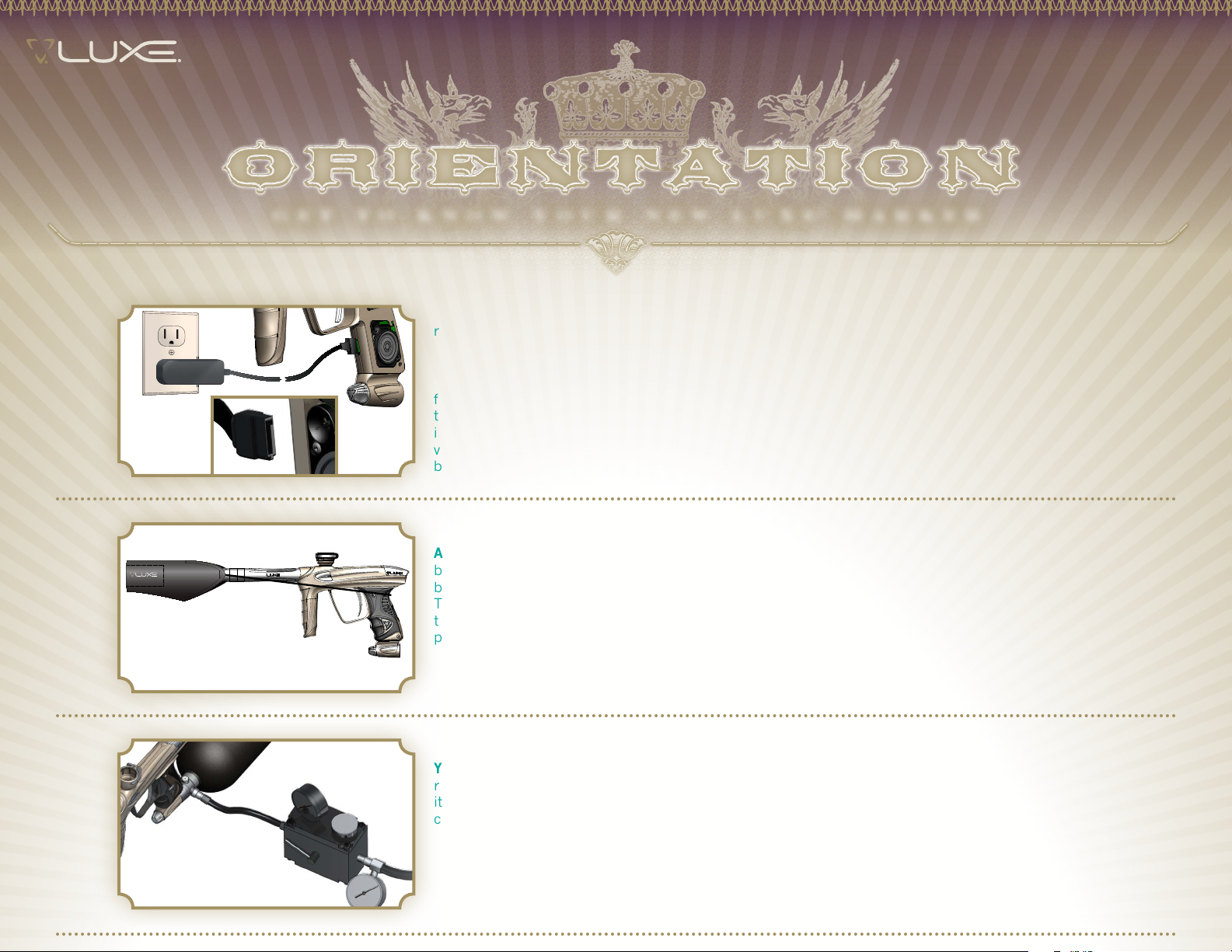
STEP ONE CHarGE THE BaTTErY (INCLUDED)
MAKE SURE THE LUXE®’S INTERNAL LITHIUM-POLYMER BATTERY is fully charged. Remove the rubber grip
from your Luxe® and connect the charger to the charging port on the front of the grip frame before plugging
the charger into a domestic electrical outlet. The L-shaped slot on the charger's SATA connector only fits
in one direction - make sure it is oriented correctly. The included charger will operate on either 110 or 240
volt standard AC power. The LED on the charger will glow solid red while charging, and solid green when the
battery is fully charged. Do not use the included USB/SATA atapter for charging. Reinstall the rubber grip.
2
3
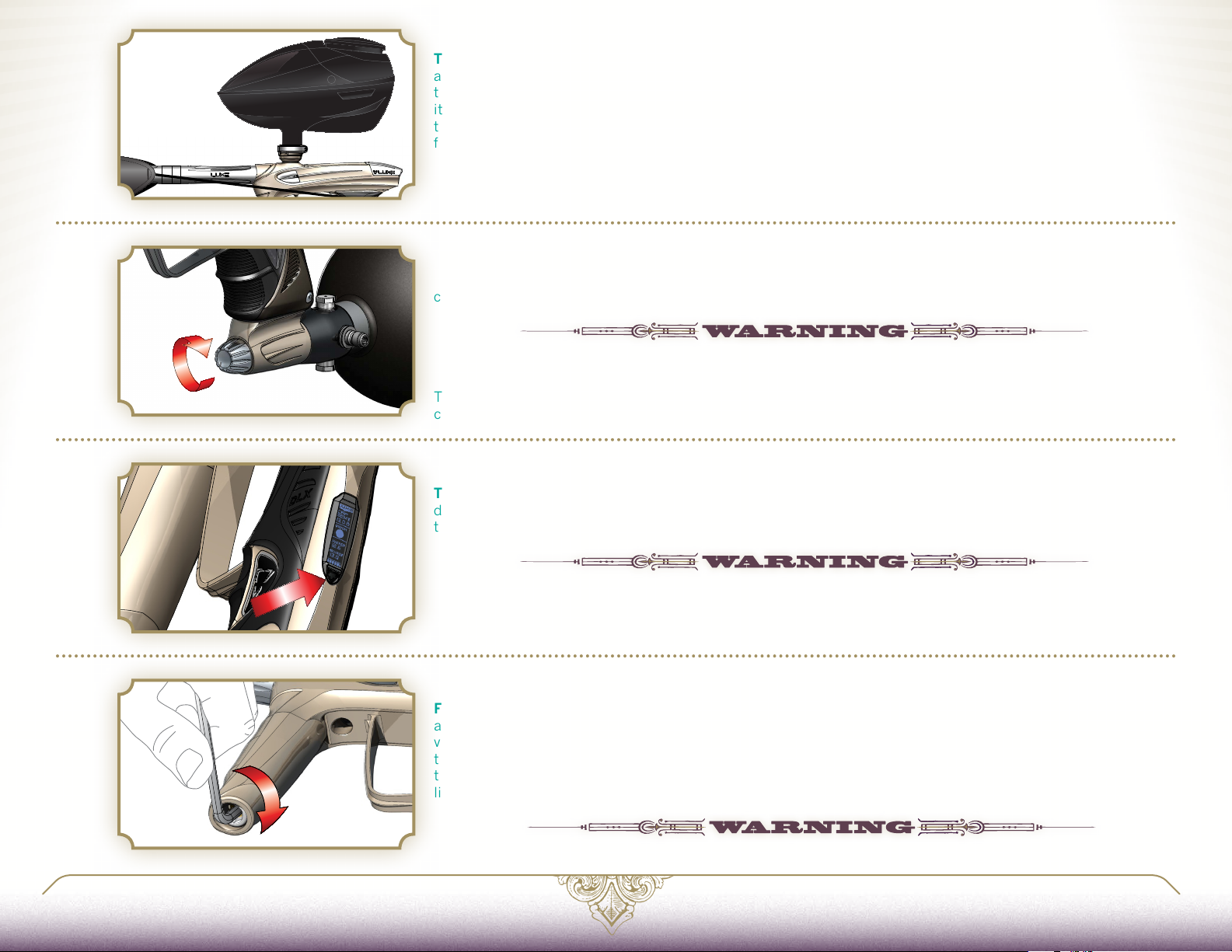
STEP TWO aFFIX THE BarrEL BLOCkEr (INCLUDED)
ASSEMBLE THE LUXE® BARREL (see
blocker over the barrel and secure its cord as far back on the Luxe® body as possible, cinching it tight. The
barrel blocker is a critical piece of paintball safety equipment—nearly as important as paintball goggles.
The barrel blocker must be fully seated on the marker's muzzle and secured in place with its strap any time
the marker is stored or handled in an area where people are not properly protected by paintball goggles or
paintball field netting.
STEP THrEE FILL & INSTaLL YOUr aIr TaNk (SOLD SEParaTELY)
YOUR LUXE® IS DESIGNED TO OPERATE PROPERLY with high pressure compressed air (HPA—also commonly
referred to in paintball as nitrogen or nitro) as its power source. Mount your air system and have it filled, following
its manufacturer’s directions. If using a screw-in style compressed air system, first turn the Luxe® bottom-line
control knob counterclockwise one and a half turns, then screw the air system into the back of the ASA.
HARDWARE 3.4) and screw it into your Luxe®. Slide the included barrel
Page 6
4
STEP FOUr INSTaLL YOUr LOaDEr (SOLD SEParaTELY)
THE ANTI-CHOP VISION SYSTEM IN YOUR LUXE® will allow it to work with any loader. Best performance
and highest rate of fire however, will only be possible with a high performance force-feed loader system. Open
the marker's locking feedneck by pulling the lock lever away from the neck, then insert the loader and secure
it in place by folding the lever back to its locked position. Loader necks vary in size from brand to brand. If
the loader does not fit securely or the lock lever does not easily close, see Orientation 1.3 in this manual for
feedneck clamp adjustment instructions.
STEP FIVE TUrN ON aIr
GENTLY GAS UP YOUR LUXE® BY SLOWLY TURNING the air system on or by turning the Luxe® bottom-line
control knob clockwise.
A GENTLE RISE IN PRESSURE IS IMPORTANT, AS A SUDDEN BLAST MAY REDUCE THE SERVICE LIFE OF PRESSURE
SEALS WITHIN YOUR LUXE®.
5
6
7
The Luxe® bottom-line control knob must be turned off (counterclockwise) before removing screw-in
compressed air systems.
STEP SIX POWEr ON YOUr LUXE® markEr
TURN THE MARKER ON BY DOUBLE-CLICKING (quickly pressing twice) the power button, or by holding it
down for two seconds. Turn it off by pressing and holding the power button for two seconds. When the Luxe®
turns on, the OLED display will be activated, indicating the marker's status.
ALTHOUGH THE POWER BUTTON SERVES AS THE LUXE®’S SAFETY SWITCH TO PREVENT ACCIDENTAL FIRING, IT
SHOULD NEVER BE RELIED UPON IN PLACE OF A BARREL BLOCKER AND PROPER PAINTBALL EYE PROTECTION.
STEP SEVEN aDJUST LUXE® VELOCITY
FILL THE HOPPER WITH PAINTBALLS and turn it on. While wearing ASTM compliant paintball goggles, in an
area where all bystanders are protected, remove the barrel blocker and fire over a chronograph to measure the
velocity. Using a 5/32-inch allen wrench on the adjuster in the bottom of the vertical regulator, turn clockwise
to increase velocity/pressure, and counterclockwise to decrease. Take three or four shots after every adjustment
to allow the gas pressure inside your Luxe® to stabilize. Adjust until the marker is firing consistently within the
limits for the field where you are playing.
NEVER ADJUST YOUR LUXE TO FIRE AT GREATER THAN 300 FEET PER SECOND.
LUXEPaINTBaLL.COm
866. 573.LUXE(5893)
PaGE 7 1.1 QUICk STarT
Page 7
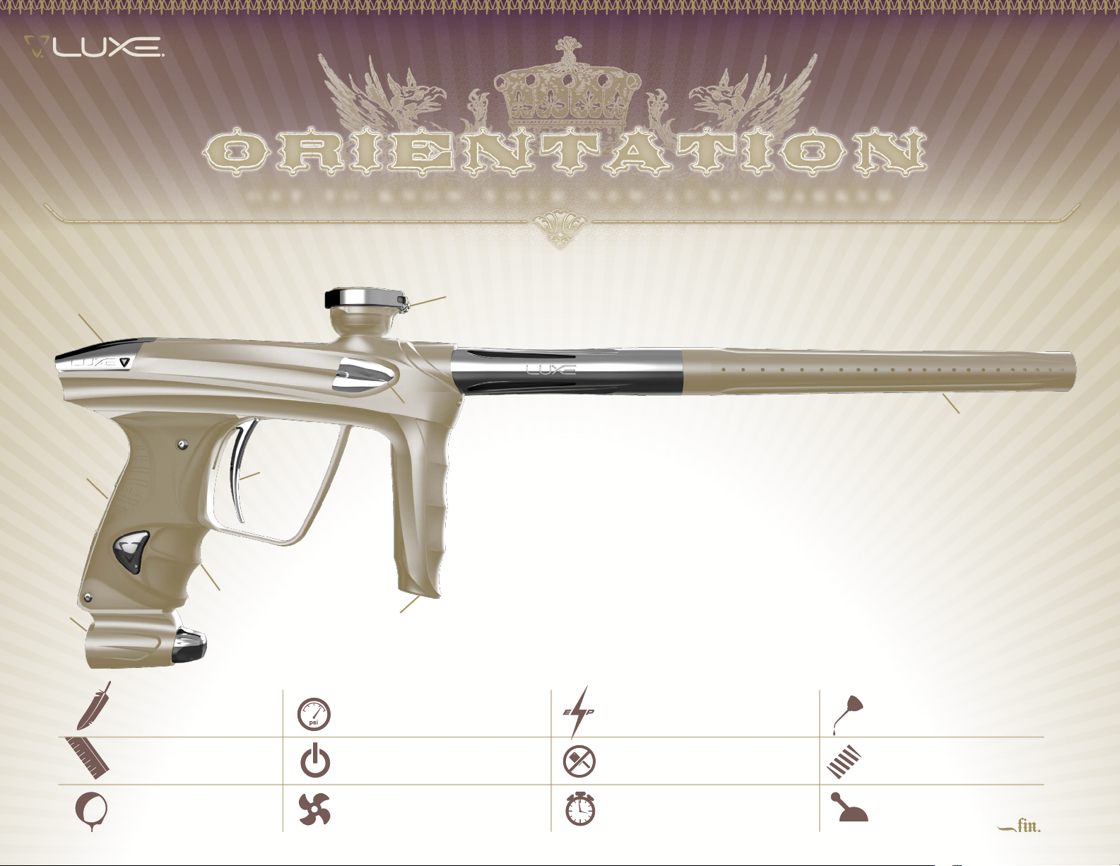
GET TO KNOW YOUR NEW LUXE® MARKER
Basic Guide to
LUXE® SPECS & FEATURES
6
3
1
4
OrIENTaTION 1
AIR 2
HARDWARE 3
SOFTWARE 4
MAINTENANCE 5
ADV. MAINTENANCE 6
7
8
2
5
maIN CONTrOL S & FEaTUrES
1
2
3
4
5
6
7
8
9
POWER/OLED DISPLAY
TRIGGER
GRIP
LUX E® IN TE GR ATED A IR B OTTOM LI N E
LUX E® IN TE GR ATED A IR V E RTICAL R EGUL ATOR
LUX E® POWER C ORE
CLAMPING FEEDNECK
LUX E® QUIC K-S NA P BA LL DETEN T ASS EMBLY (2)
LUX E® 3-PI EC E BA R REL SYSTEM
9
WEIGHT
1.8 lbs
DIMENS IONS
8.25 x 7 in
PAINT SIZE
.68 caliber Compressed Air Uncapped 11
OPERATI NG PRESSURE
190 psi
POWER SOURCE
LiPo Rechargeable Battery
PROPELLANT RATE OF F IRE
OPERATI NG METHOD
Electropneumatic
ANTI- CHOP SYSTEM
630nm Vision Break Beam
LUBRIC ANT
GR33SE
BARREL THREADS
Smart Parts
FIRI NG MODES
Page 8
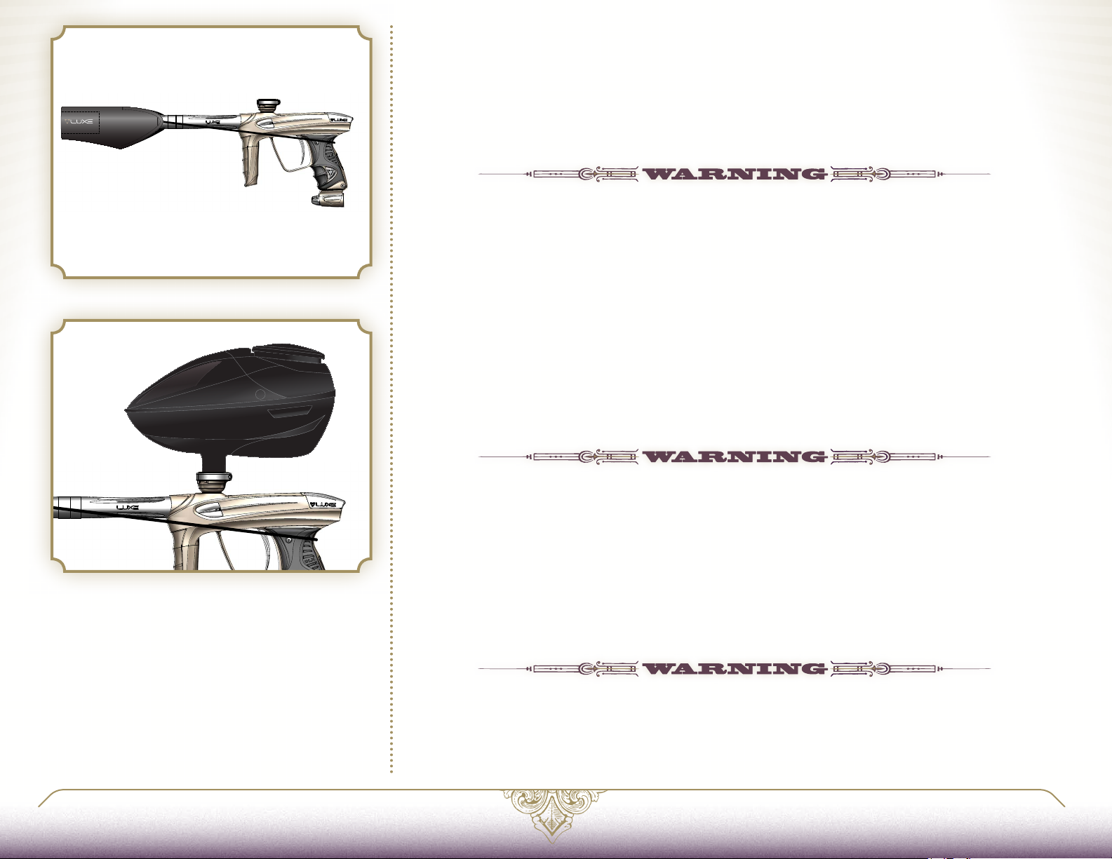
FIG. 1
OrIENTaTI ON 1. 2 INSTaLLING THE BarrEL BLOCkEr
THE BARREL BLOCKING DEVICE IS A CRITICAL PIECE of paintball safety equipment—nearly as important
as paintball goggles. The Barrel Blocker serves to protect against accidental discharge of a paintball by
catching it before it can cause harm. A Barrel Blocker is included with the Luxe® and must be used every
time it is handled in an area where people or property are not properly protected by paintball goggles or
paintball field netting. To use the Barrel Blocker simply slip it over the end of the barrel and stretch its cord
back over the rear of the Luxe® [FIG. 1.] Use the strap’s adjuster to cinch the strap tight, so that the Barrel
Blocker can provide protection against accidental discharge of a paintball.
THE BARREL BLOCKER SHOULD ONLY BE REMOVED WHEN THE LUXE® IS ON A “LIVE” PAINTBALL FIELD AND ALL
PERSONS INVOLVED ARE WEARING PROPER PAINTBALL PROTECTION.
OrIENTaTI ON 1. 3 SELECTING aND INSTaLLING a LOaDEr
YOUR LUXE® IS A HIGH PERFORMANCE PROFESSIONAL GRADE PAINTBALL MARKER. Although its
Vision anti-chop system will allow it to operate properly with any paintball loader without fear of chopping
paint, a high-end forced-feed loader must be used to achieve high rates of fire.
The Luxe® is equipped with a locking feedneck, which allows it to adapt to variance in hopper neck sizes,
and to release hoppers quickly when desired, but hold them securely on the field [FIG. 2.] Pulling the
lock lever away from the feedneck moves it to the open, or unlocked position. While it is open, the locking
mechanism may be adjusted with a 1/8-inch allen wrench opposite the latch pivot. Turning the wrench
clockwise will cause the feedneck to grip tighter, while turning it counterclockwise will result in a better fit
for larger hopper necks. Place the hopper in the feedneck, and secure it by closing the lever. If the latch
is difficult to close, do not force it. Instead, open it fully, then turn the adjuster counter-clockwise and try
again until you have adjusted for a perfect fit.
FIG. 2
LUXEPaINTBaLL.COm
OVER-TIGHTENING THE FEED NECK CAN CAUSE DAMAGE TO ITS LATCHING MECHANISM. DO NOT OVER-TIGHTEN.
OrIENTaTI ON 1. 4 HaNDLING THE LiPo BaT TErY
INCLUDED WITH YOUR LUXE® IS A RECHARGEABLE LITHIUM-POLYMER BATTERY. Do not expose the
battery to high temperatures, such as strong sunlight or in a vehicle during hot weather. Do not expose the
battery to high levels of static electricity. These situations may cause damage, leading to fire or explosion.
If the battery leaks, avoid contact with the fluids. In case of eye contact, do not rub. Rinse with clean
running water and seek medical attention immediately, or loss of sight may occur. If the battery gives off an
odor, generates heat, becomes discolored/deformed or appears abnormal, remove it from any connected
device and place in a metal box for immediate disposal. Dispose of used Luxe® batteries through a battery
recycling program, as discarded batteries pose a risk of fire or environmental contamination.
DO NOT IMMERSE THE BATTERY IN LIQUID. STORE IN A COOL, DRY ENVIRONMENT WHEN NOT IN USE. DO NOT
REVERSE POSITIVE (+) AND NEGATIVE (-) TERMINALS OR SHORT-CIRCUIT. DO NOT CONNECT THE BATTERY TO
AN ELECTRICAL OUTLET. DO NOT STRIKE OR THROW THE BATTERY AGAINST A HARD SURFACE. DO NOT MODIFY,
PIERCE, OR SOLDER NEW CONNECTIONS TO THE BATTERY. STORE AND TRANSPORT THE BATTERY IN A CASE
WHICH PROTECTS IT FROM DAMAGE OR CONTACT WITH SHARP OR METAL OBJECTS WHEN NOT IN USE.
866. 573.LUXE(5893)
PaGE 9 1.2 INSTaLLING THE BarrEL BLOCkEr
Page 9
WHAT YOUR LUXE® NEEDS TO BREATHE
ORIENTATION 1
aIr 2
HARDWARE 3
SOFTWARE 4
MAINTENANCE 5
ADV. MAINTENANCE 6
Basic Guide to THE
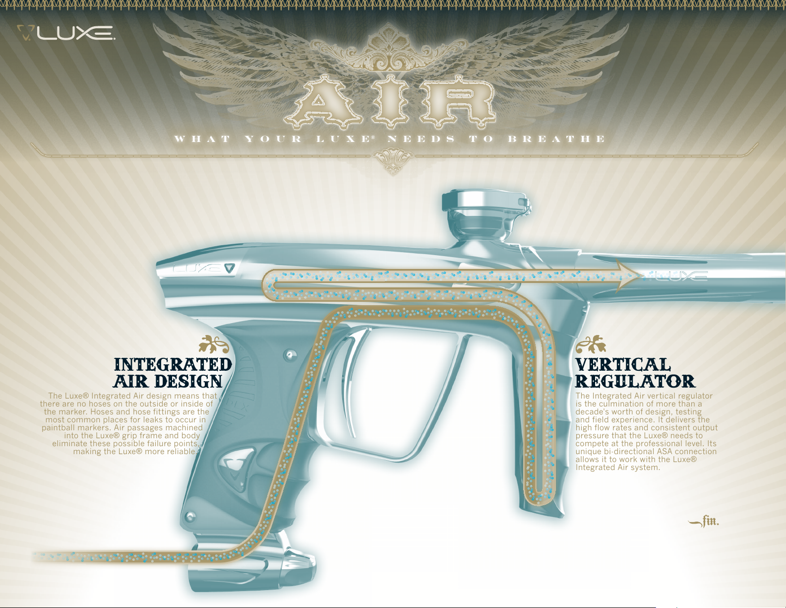
LUXE® INTEGRATED AIR SYSTEM
INTEGRATED
AIR DESIGN
The Luxe® Integrated Air design means that
there are no hoses on the outside or inside of
the marker. Hoses and hose fittings are the
most common places for leaks to occur in
paintball markers. Air passages machined
into the Luxe® grip frame and body
eliminate these possible failure points,
making the Luxe® more reliable.
VERTICAL
RE GULATOR
The Integrated Air ver tical regulator
is the culmination of more than a
decade's worth of design, testing
and field experience. It delivers the
high flow rates and consistent output
pressure that the Luxe ® needs to
compete at the professional level. Its
unique bi-directional ASA connection
allows it to work with the Luxe®
Integrated Air system.
Page 10
aIr 2.1 aBOUT COmPrESSED aIr
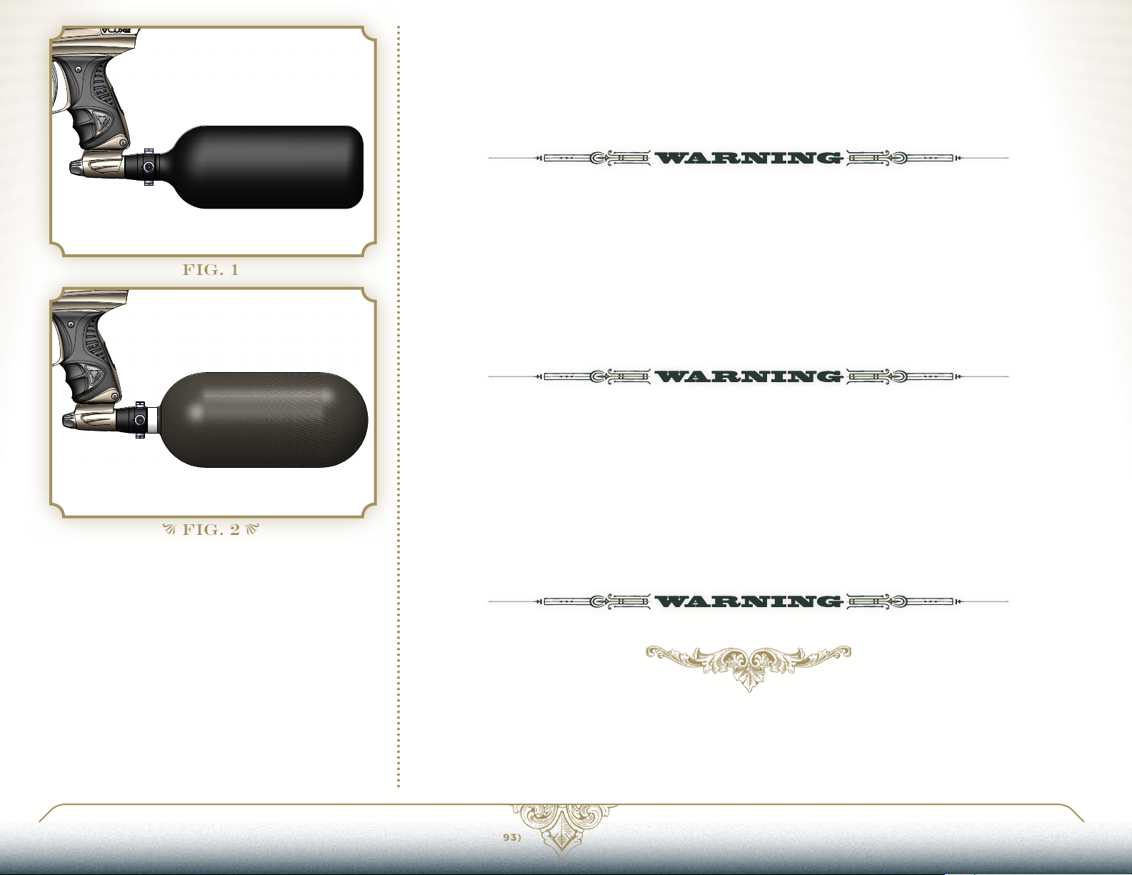
YOUR LUXE® IS DESIGNED TO OPERATE ON HIGH-PRESSURE AIR (HPA) which is stored in cylinders
(tanks) at pressures of up to 3,000 [FIG. 1] or 4,500 psi [FIG. 2.] The storage cylinder, along with the
regulator mounted in its neck forms an HPA system. There are two main types of HPA systems, those on
which the regulator’s output pressure is adjustable, and those for which their regulator is pre-set to deliver
a fixed output pressure. HPA systems designed to screw into an ASA are usually pre-set to provide 400 psi
(low pressure output) or 800 psi (high pressure output.)
DO NOT USE CO2 WITH YOUR LUXE®. USE THE LUXE® ONLY WITH COMPRESSED AIR SYSTEMS FEATURING TWO
BURST DISKS, ONE FOR THE HIGH PRESSURE SIDE OF THE REGULATOR, AND AN 1800 PSI RATED BURST DISK
FOR THE DOWNSTREAM SIDE OF THE REGULATOR. THE 1800 PSI (ALSO SOMETIMES MARKED 1.8K) PROVIDES
CRITICAL PROTECTION IN CASE OF A REGULATOR LEAK, AND ITS ABSENCE MAY CAUSE DAMAGE TO THE LUXE®
AND OR SERIOUS INJURY.
FIG. 1
FIG. 2
If you are using your Luxe® with an adjustable output compressed air system, it should be set to deliver
about 650 psi. The Luxe® vertical regulator can accommodate a wide range of input pressures, and lower
them to the marker’s operating pressure, so exact adjustment of the air system is not critical, and either
low output, or high output pre-set HPA systems may be used. If using a screw-in style air system, the
Luxe® on/off bottom-line or similar is recommended, as the on/off control is important for proper set-up
and degassing.
NEVER USE OIL OR ANY PETROLEUM BASED CLEANER OR LUBRICANT IN A COMPRESSED AIR REGULATOR OR
CYLINDER. EXPOSURE TO PRESSURIZED AIR INCREASES OIL’S FLAMMABILITY AND CAN CAUSE A SERIOUS
SAFETY HAZARD. ONLY USE MANUFACTURER RECOMMENDED LUBRICANTS WITH COMPRESSED AIR SYSTEMS,
AND FOLLOW THE MANUFACTURER’S MAINTENANCE AND OPERATION INSTRUCTIONS EXPLICITLY.
Regardless of the type of air system used, be sure to turn it on by slowly opening its control valve (either
on the HPA system, or on/off bottom-line, depending on the configuration) so that the gas pressure in the
Luxe® rises gently, rather than jumping to full pressure. Slower pressurization will maximize the service life
of the seals and low pressure components in the Luxe®. The Luxe® offers multiple options for mounting
compressed air systems. Located on the bottom of the grip frame are a pair of industry standard 10-32
screw holes for air system mounting. Located forward and to the side of these holes is the Luxe® grip
integrated gas port. A small o-ring sitting in a recess at the gas port provides an airtight seal.
DEGAS AND UNLOAD THE LUXE® BEFORE MAKING ANY AIR SYSTEM CHANGES.
LUXEPaINTBaLL.COm
866. 573.LUXE(5893)
PaGE 11 2.1 aBOUT COmPrESSED aIr
Page 11
WHAT YOUR LUXE® NEEDS TO BREATHE
ORIENTATION 1
aIr 2
HARDWARE 3
SOFTWARE 4
MAINTENANCE 5
ADV. MAINTENANCE 6
aIr 2.2 INSTaLLING aN aIr SYSTEm
INCLUDED WITH YOUR LUXE® IS A BOTTOM-LINE style integrated air on/off ASA for use with screw-in
style compressed air systems. The grip integrated ASA can be mounted directly to the Luxe® grip frame,
or mounted with forward (included) or reverse (optional) grip integrated air rails.
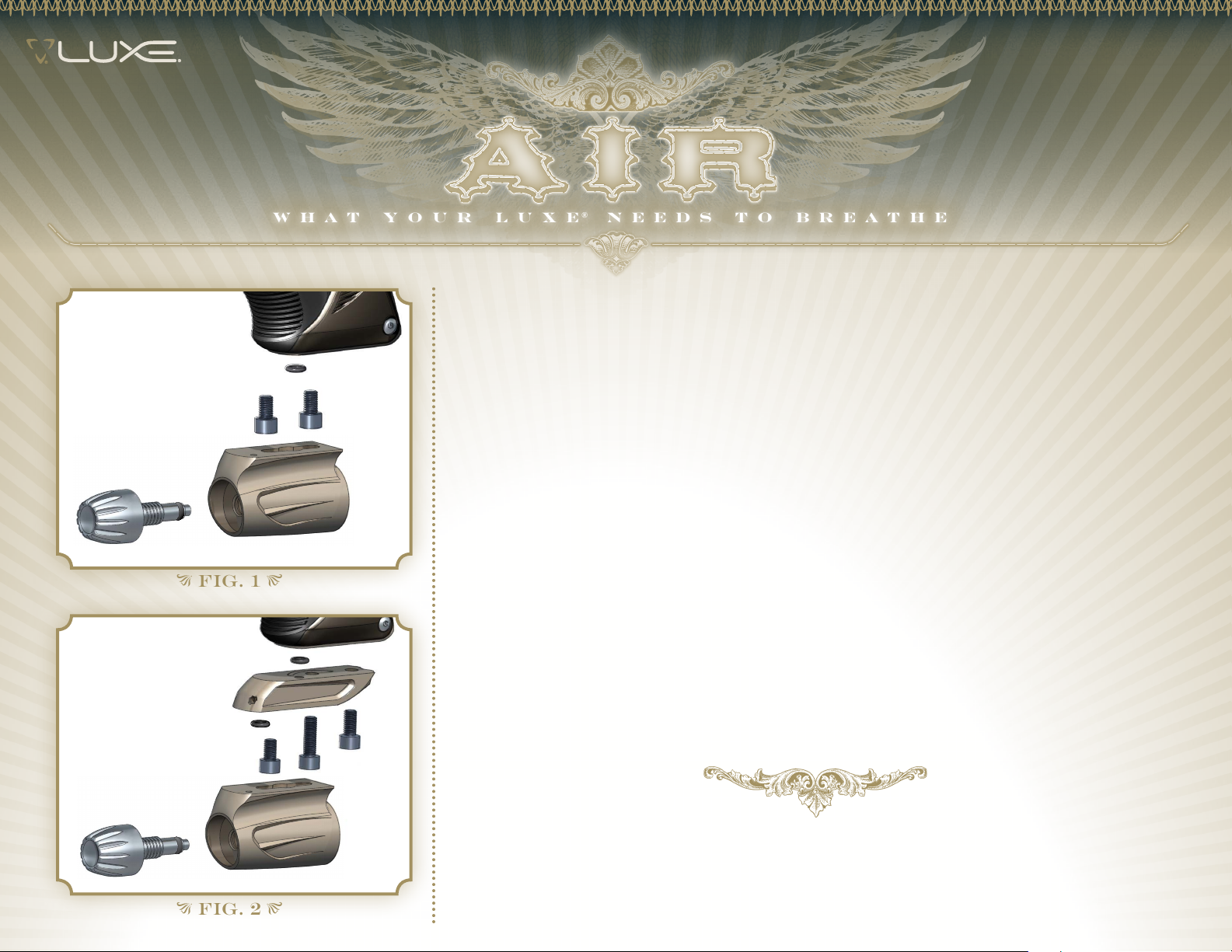
When mounting the bottom-line adapter directly to the grip frame, it must first be disassembled by
unscrewing and removing its control knob. Each of the short 10-32 socket head cap screws are inserted
in the center slot in the top of the bottom-line adapter [FIG. 1,] then slid to the front or back. A 5/32-inch
allen wrench is guided up through holes in the bottom of the adapter to tighten the screws. If needed, the
control-knob's o-ring may be lightly lubricated with GR33SE™ before it is reinstalled.
The Air Integrated Rail offers an alternative configuration with a slightly lower and forward placement of
the HPA system. A short socket head cap screw is used through the rail’s rear hole to secure it to the grip
frame [FIG 2.] A long socket head cap screw is slid into the bottom-line's rear mount point while a short
socket head cap screw is used in the front, installing with the same procedure as direct-mounting.
FIG. 1
FIG. 2
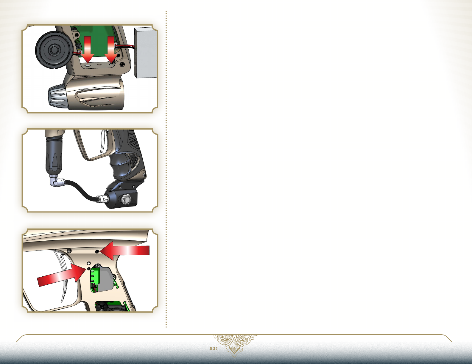
When installing a new air system, accessory or mount, the grip must be removed and the battery removed
from the Luxe® (see HARDWARE 3.6.) Only use mounting screws which will reach through the air system,
accessory or mount, and fully engage the screw threads in the grip frame, but not extend into the open
space of the grip frame far enough that they interfere with the placement of the battery. Installing mount
screws while the battery is removed will ensure that a screw which is too long does not accidentally
damage the lithium-polymer battery [FIG. 3.]
In addition to grip integrated air systems, the Luxe® may also use standard hose based air systems and
accessories, bypassing the grip integrated air system. Such accessories are mounted the same way, but
will require the use of a vertical regulator (see ADVANCED MAINTENANCE 6.2 for removal instructions) which
accepts input via macroline or steel braided hose and provides output in the range of 170-220 psi [FIG. 4.]
Page 12
aIr 2.3 FEaTHErTOUCH
YOUR LUXE® IS IS EQUIPPED WITH A FEATHERTOUCHTM MANIFOLD allowing for extra-gentle treatment
of the most brittle paintballs and an unbeatably smooth firing cycle. The FeatherTouchTM control restricts
the flow of gas leaving the forward portion of the Luxe Power CoreTM. This provides a cushion of air which
softens the bolt’s forward motion. When using the Luxe
to clean and grease the bolt more frequently. Additionally, anti-FSDO adjustments may be necessary for
reliable operation. Maintenance is more critical with FeatherTouch
the unmatched feel and fragile paint handling.
TM
in Fe a t h e rTo uchTM mode, it will be necessary
TM
, but top professional players swear by
FIG. 3
FIG. 4
fEAThERTOuch
TM
To activate FeatherTouchTM the FeatherTouchTM control screw is moved from its storage location to the
Fe a t h e rTouch
the screw from the manifold.
With the Luxe
remove the control screw from its storage position [FIG 5.] The control screw has a small black o-ring on
its front. The o-ring may cause the control screw to stick in the threaded hole, requiring a tap on the grip
frame to work it loose. Make sure the o-ring is correctly seated on the control screw when reinstalling.
When not in use, the control screw should be returned to its threaded storage hole for safekeeping.
Dwell Adjustment will typically need to be increased by 2 milliseconds when FeatherTouch
dwell setting of 14 milliseconds is ideal..
TM
hole in the LuxeTM solenoid manifold. De-activating FeatherTouch simply requires removing
TM
unloaded and degassed, remove the rubber grip, then use a 1/16-inch allen wrench to
TM
is turned on. A
STORAGE
FIG. 5
LUXEPaINTBaLL.COm
866. 573.LUXE(5893)
PaGE 13 2.2 INSTaLLING aN aIr SYSTEm
Page 13
ORIENTATION 1
HarDWarE 3
SOFTWARE 4
MAINTENANCE 5
ADV. MAINTENANCE 6
HarDWarE 3.1 aDJUSTING VELOCITY
THE VELOCITY, OR SPEED AT WHICH YOUR LUXE® FIRES a paintball, must be measured and adjusted
to below the paintball field’s velocity limit immediately before each day of play, for player safety. Fill the
hopper with paintballs and turn it on.
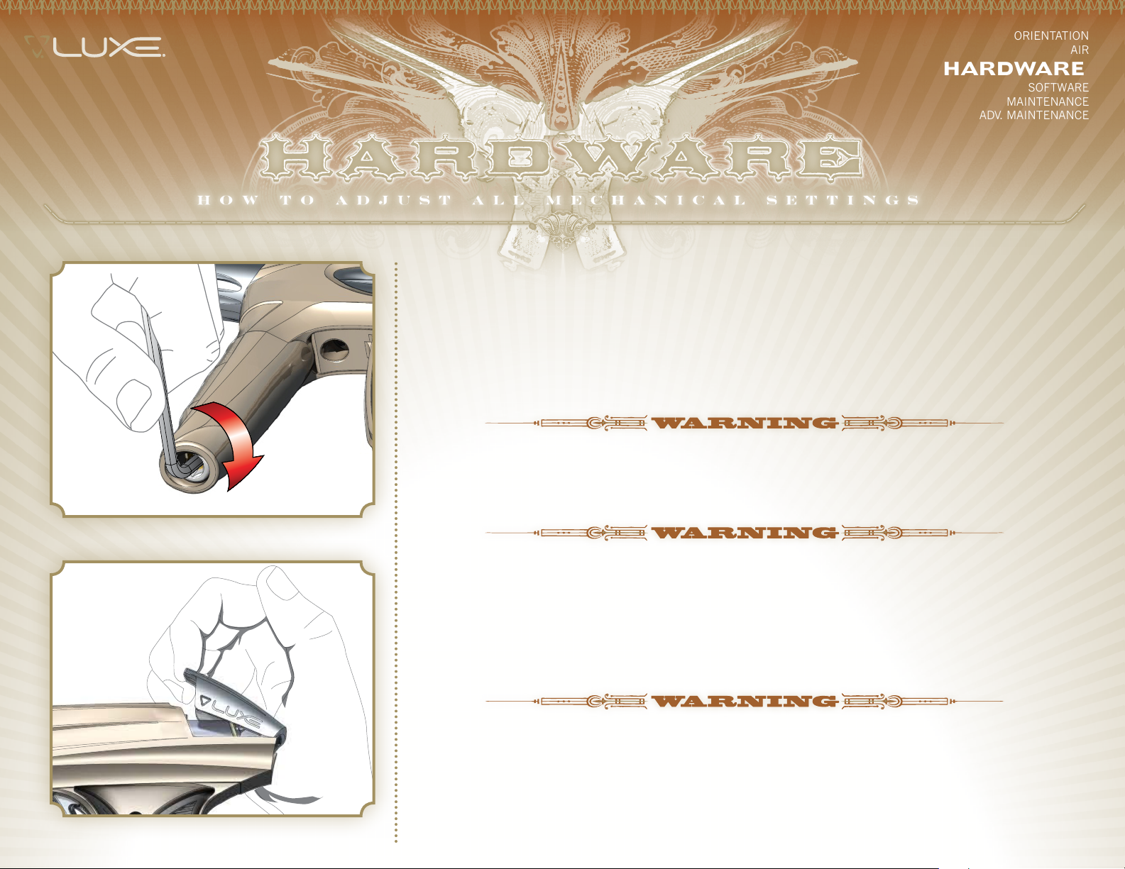
While wearing ASTM compliant paintball goggles, in an area where all bystanders are protected, remove the
barrel blocker and fire over a chronograph to measure the velocity. Using a 5/32-inch allen wrench on the
adjuster in the bottom of the Luxe® Vertical Regulator, turn clockwise to increase velocity/pressure [FIG. 1,]
and counterclockwise to decrease.
DO NOT ATTEMPT TO ADJUST THE LUXE® VERTICAL REGULATOR WITH LARGER SIZED ALLEN WRENCHES. THESE ARE
USED TO REMOVE AND DISASSEMBLE THE REGULATOR, WHICH MUST NOT BE DONE WHILE IT IS PRESSURIZED.
AIR 2
FIG. 1
FIG. 2
Take three or four shots after every adjustment to allow the gas pressure inside the Luxe® to stabilize.
Adjust and retest until the marker is firing consistently within the limits for the field where you are playing.
ALWAYS MEASURE THE VELOCITY OF PAINTBALLS FIRED BY THE LUXE® BEFORE USE, AND NEVER ADJUST TO
FIRE ABOVE 300FPS (91.44 M/S.)
HarDWarE 3.2 DEGaSSING THE SYSTEm
BEFORE STORAGE, TRANSPORT OR MAINTENANCE, your marker will need to be unloaded and degassed.
In an area where it is safe to shoot and while wearing paintball goggles, loosen the Luxe®’s clamping
feedneck and remove the loader. By turning the marker upside down, you can empty any extra paintballs
from the feedneck into your hand.
EVEN WITH ITS GAS SUPPLY TURNED OFF, THE REGULATOR AND GAS PASSAGES IN THE LUXE® WILL CONTAIN
ENOUGH PRESSURE TO FIRE MULTIPLE SHOTS UNTIL THE MARKER IS DEGASSED.
Turn off your HPA system either with its on/off valve, or the on/off valve of a connected bottom-line
adapter. Lift the quick-strip latch upward to vent pressure from the Power Core [FIG 2.] As the Power Core is
depressurized, it will make a sound similar to a soda can being opened. If you hear the sound of escaping
gas for more than a second or two, your HPA system has not been turned off. Turn off your HPA system and
repeat the degassing procedure.
Page 14
1
2
3
FIG. 3
4
Once the Luxe® has completely degassed, there will be no more hissing sound. If performing maintenance
on the Luxe®, remove the Power Core (see MAINTENANCE 5.1) to protect against accidental pressurization—
otherwise, re-close the latch. If using a screw-in style HPA system, unscrew the system from the marker’s
bottom-line ASA. Pay careful attention to make sure the HPA system regulator is unscrewing from the
Luxe®’s ASA, rather than the tank unscrewing from its regulator.
DO NOT LIFT THE QUICK-STRIP LATCH UNTIL THE GAS SUPPLY HAS BEEN TURNED OFF. IF THIS IS DONE
ACCIDENTALLY, TURN OFF THE GAS SUPPLY IMMEDIATELY. ATTEMPTING TO CLOSE THE LATCH WHILE THE GAS
SUPPLY IS ON MAY RESULT IN O-RING DAMAGE.
HarDWarE 3.3 aDJUSTING THE TrIGGEr
YOUR LUXE® IS EQUIPPED WITH A 4-POINT ADJUSTABLE TRIGGER, providing complete versatility to
both the feel and length of the trigger pull. The Luxe® can be adjusted to a super-sensitive hair trigger,
though many players find that a slightly longer, and heavier trigger pull is easier to walk to higher rates of
fire. Perform trigger adjustments while the Luxe® is unloaded and degassed. Luxe® Training Mode (see
PROGRAMMING PULL-OUT) can be used to determine the effectiveness of changes in trigger adjustment.
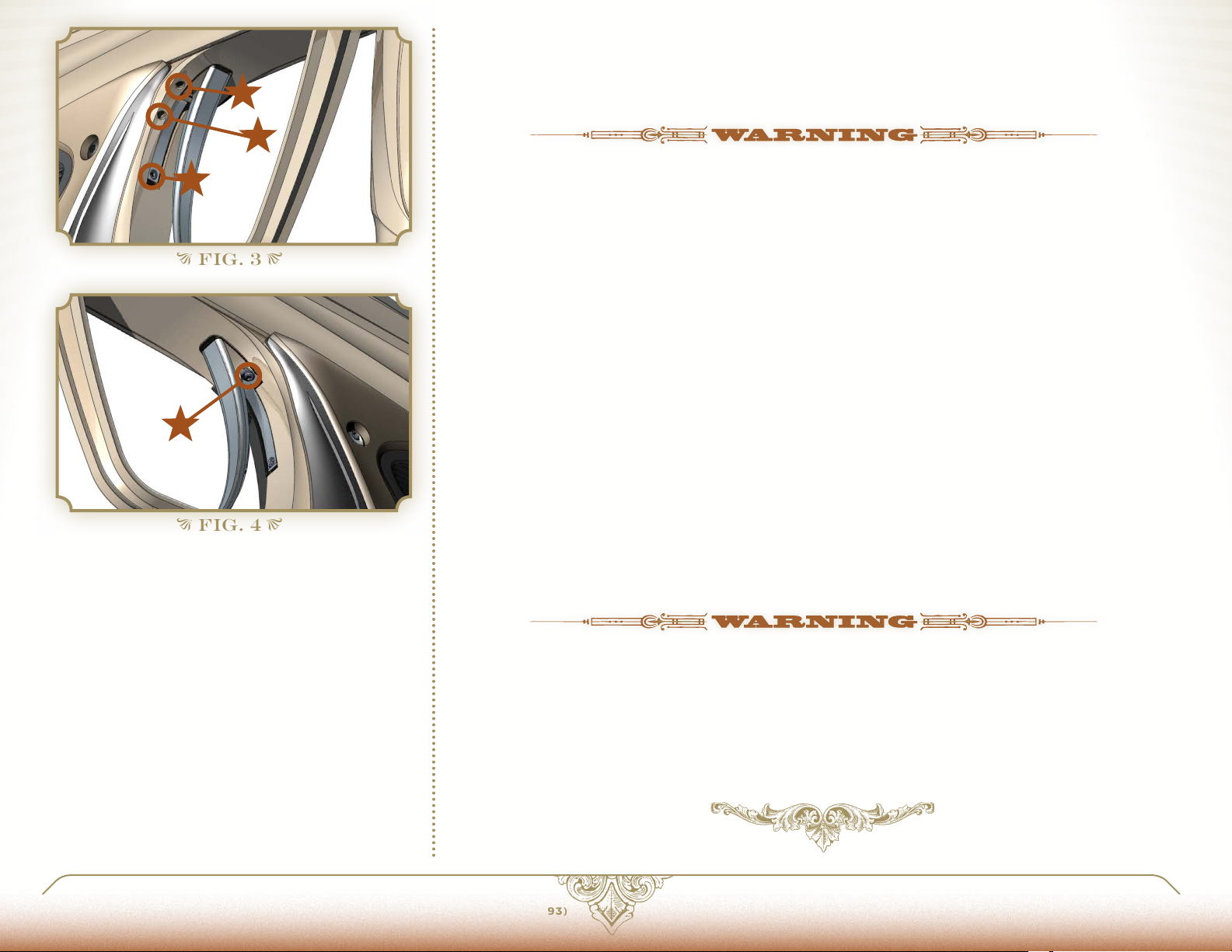
POST-TraVEL The post-travel adjustment sets how far back the trigger can travel, affecting the area
of the trigger pull that occurs after the Luxe® fires. Turning the adjustment screw clockwise with an
0.050-inch allen wrench will reduce post-travel, limiting how far back the trigger can swing, while turning
counterclockwise will increase it. The post-travel limit must be set to stop the trigger before it is brought to a
stop by the trigger switch.
PrE-TraVEL The pre-travel adjustment determines how far forward the trigger can swing, affecting the
area of the trigger pull that occurs before the Luxe® fires. Pre-travel is adjusted with an 0.050-inch allen
wrench in the pre-travel adjustment screw. Turn clockwise to reduce pre-travel, and counterclockwise to
increase.
FIG. 4
1 p os t-tr av e l
2 pre -t r av e l
3 activation point
4 re sis tance
LUXEPaINTBaLL.COm
aCTIVaTION POINT The activation point setting determines the point in the trigger pull at which the
Luxe® trigger switch is activated, signaling the marker to fire. As the screw is turned clockwise with a 0.050inch allen wrench, it will extend out the back of the trigger, closer to the trigger switch, causing the trigger to
be activated earlier in the trigger pull. Due to the limited space to access this adjustment, use of a ball-end
allen wrench is advised.
USE CAUTION WHEN ADJUSTING THE ACTIVATION POINT AND POST-TRAVEL ADJUSTMENT. WHEN PROPERLY
ADJUSTED, THE TRIGGER SHOULD COME TO A SOLID STOP AGAINST THE POST TRAVEL ADJUSTMENT SCREW.
IF IT COMES TO A SOFTER STOP CAUSED BY THE ACTIVATION POINT ADJUSTMENT SCREW OR REAR OF THE
TRIGGER PRESSING AGAINST THE TRIGGER SWITCH, THEN TRIGGER SWITCH AND OR CIRCUIT BOARD DAMAGE
MAY RESULT FROM RAPID OR HARD PULLS ON THE TRIGGER.
TrIGGEr rESISTaNCE Trigger resistance, or the weight of the trigger pull may be adjusted with a 0.050-
inch allen wrench in the trigger resistance adjustment screw. Turning clockwise increases pressure on the trigger
return magnet, for increased resistance, while turning counterclockwise decreases pressure on the trigger.
866. 573.LUXE(5893)
PaGE 15 3.1 aDJUSTING VELOCITY
Page 15
ORIENTATION 1
AIR 2
HarDWarE 3
SOFTWARE 4
MAINTENANCE 5
ADV. MAINTENANCE 6
Basic Guide to the
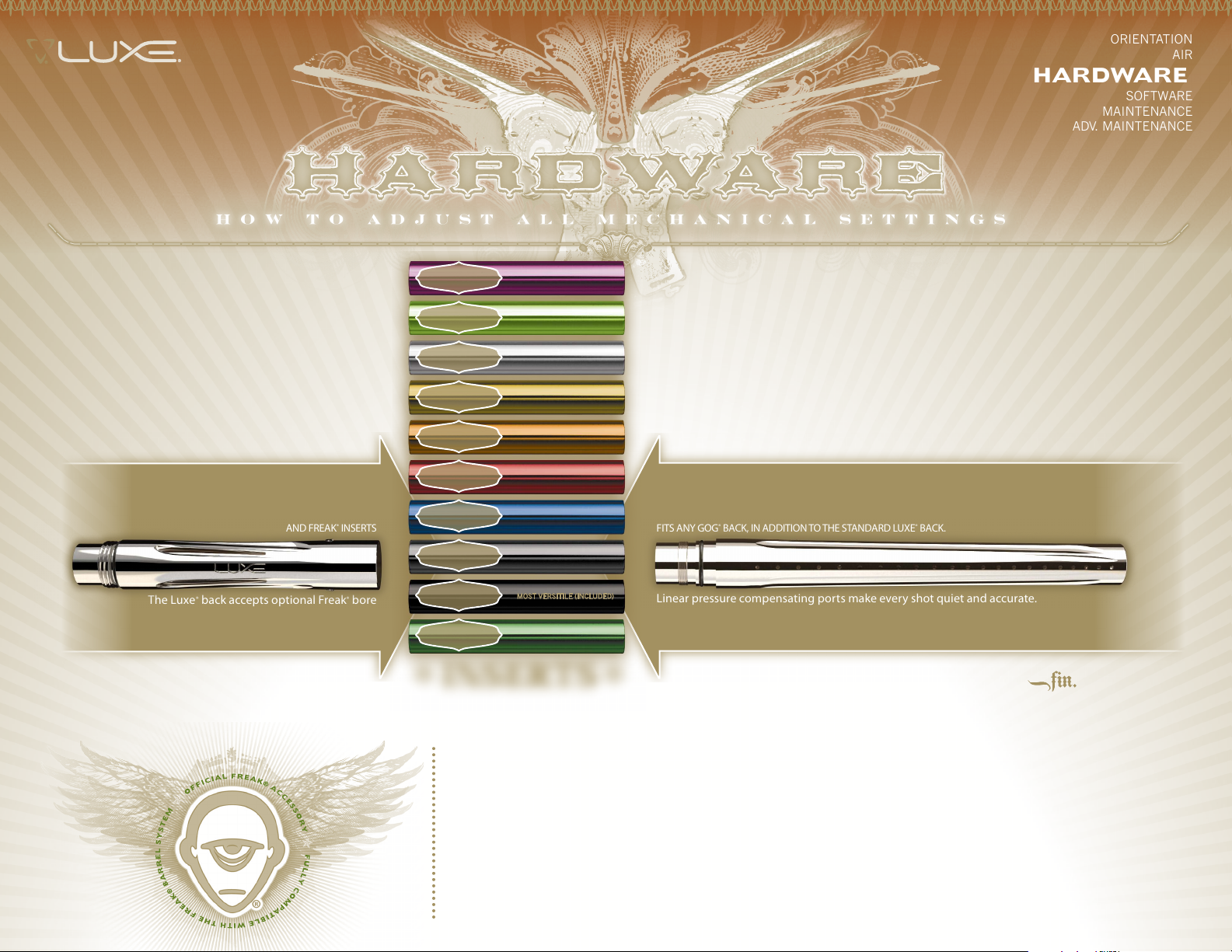
LUXE® 3-PIECE
BARREL SYSTEM
BACK
ACCEPTS ALL GOG® FRONTS
AND FREAK
The Luxe® back accepts optional Freak® bore
inserts, allowing it to quickly adapt to changing
paint conditions.
®
INSERTS
.
675
.
677
.
679
.
682
.
684
.
687
.
689
.
691
.
693
.
695
NEW SIZE
NEW SIZE
FITS SMALLER/SHRUNKEN PAINT
MOST VERSITILE (INCLUDED)
FITS LARGER /SWOLLEN PAINT
FRON T
FITS ANY GOG® BACK, IN ADDITION TO THE STANDARD LUXE® BACK.
Linear pressure compensating ports make every shot quiet and accurate.
GOG® barrel compatibility lets you switch to optional fronts to keep pace
with changing playing conditions.
INSE RTS
AVAILABLE IN 10 COLOR CODED SIZES, FREAK BORE INSERTS CREATE THE
PERFECT FIT WITH ANY BRAND OF PAINT.
HarDWarE 3.4 LUXE® BarrEL SYSTEm
EVEN THE BEST QUALITY PAINTBALLS WILL VARY in size from one batch to the next and as weather
conditions change. Although your Luxe® can work well even with a poor paint to barrel fit, optimal
performance will be achieved with a proper fit. The ideal fit between the paintball and the barrel is found
when the ball is inserted in the bore and does not slip or roll through to the muzzle on its own, yet can
be blown out like a blowgun, using a minimal amount of breath. The barrel can be adapted to fit a wide
range of paintball sizes through the use of GOG Paintball® inserts. The .693-inch ID Luxe® bore insert
may be removed by sliding it out the back of the barrel, and inserting an appropriate sized Freak® insert
in its place. The Luxe® 3-Piece barrel is compatible with all GOG Paintball® multi-piece barrel components
providing access to a variety of optional fronts and inserts.
Page 16
HarDWarE 3.5 LiPo rECHarCHaBLE BaTTErY
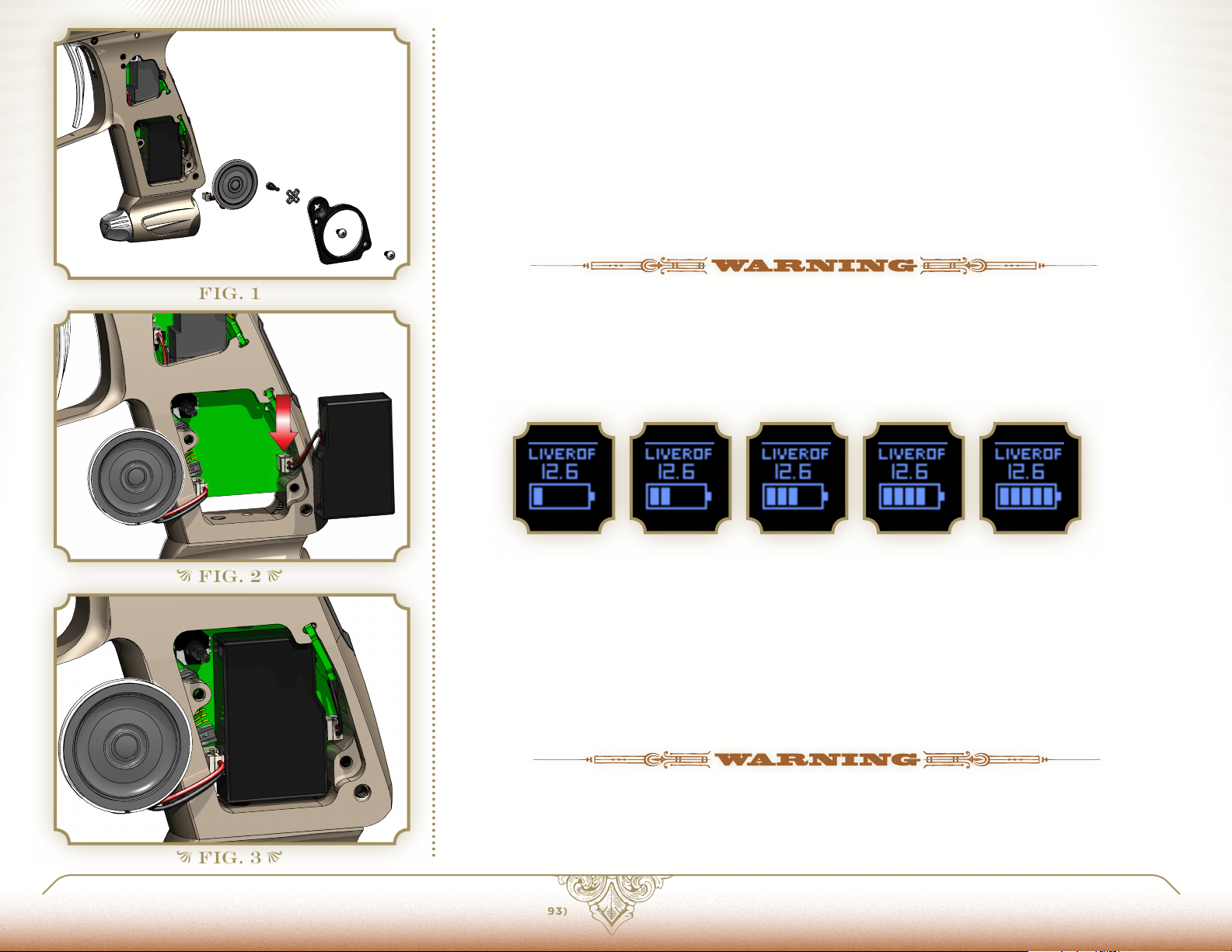
YOUR LUXE® IS EQUIPPED WITH a Lithium-Polymer (LiPo) battery. Lithium-Polymer batteries provide
consistent power output in a minimal size and weight, without suffering from charge memory effects.
To charge the Luxe®, use a 5/64-inch allen wrench to remove the four grip screws and completely remove the
grip (avoid folding the grip back from one side as this may cause damage.) Simply plug the included charger
into the marker’s charging port, and plug the adapter into a domestic power outlet. The Luxe® charger is
designed for international use, and will operate on standard mains 50 or 60 Hz AC power from 110 to 240
volts. Plug adapters may be required when using the Luxe® outside of the US, Canada or Mexico.
While the Luxe® battery is charging, the charger’s LED will glow red. It will glow green to indicate that the
charging cycle is complete. Charge time is approximately 30 minutes. The USB/SATA Luxe USB Interface
cable will not charge the battery.
FIG. 1
FIG. 2
ONLY USE THE LUXE® CHARGER, CIRCUIT BOARD AND GENUINE LUXE® BATTERY. THESE COMPONENTS CONTAIN
CRITICAL CHARGE AND DISCHARGE CONTROL CIRCUITS. USE OF AFTER-MARKET ELECTRONIC PARTS MAY
RESULT IN FIRE OR EXPLOSION.
When your Luxe® is turned on, it will display an estimate of the remaining battery charge. This will be
displayed at the bottom of the marker's OLED display. It is important to note that battery discharge rates
can be affected by various factors, including temperature. The indicated charge level is only an estimation
of the expected remaining charge life.
HarDWarE 3.6 rEPLaCING Or CHarGING THE SParE BaTTErY
SWAP LUXE® BATTERIES at least once every six months to maximize their operating life. A spare battery
that is unused for more than six months or stored completely empty may lose capacity or fail entirely.
Unload and degas your Luxe® following the instructions in this manual. Open the left side grip panel with a
5/64-inch allen wrench. Use a 1/16-inch allen wrench to remove the speaker mount. [FIG 1.]
Carefully lift out the speaker. Do not allow sharp tools like allen wrenches to snap onto the magnet, damaging the speaker cone. Take care not to strain the speaker wires. Lift out and unplug the the Lithium-Polymer
battery pack. When unplugging any component from the circuit board, pull on the connector directly, not its
wires.
FIG. 3
LUXEPaINTBaLL.COm
DO NOT PLUG A BATTERY INTO THE SPEAKER CONNECTION [FIG.2,] AS CIRCUIT BOARD DAMAGE MAY RESULT.
Install a charged battery [FIG. 3,] and plug it into the circuit board. Make sure the speaker is plugged in,
reinstall the speaker and speaker mount, taking care not to crimp or crush any of the wires, then re-secure
the grip panel. The speaker and battery connectors only fit in one direction. If a connector does not slide
smoothly onto its pins, try rotating it to determine if it has been reversed. Do not force the connectors.
866. 573.LUXE(5893)
PaGE 17 3.4 LUXE® BarrEL SYSTEm
Page 17
ORIENTATION 1
HARDWARE 3
AIR 2
SOFTWarE 4
MAINTENANCE 5
ADV. MAINTENANCE 6
SO F T WarE 4 .1 INTrODUCTION TO PrOGrammING
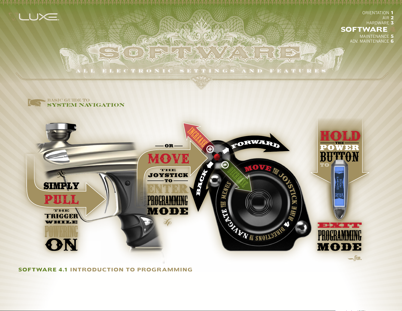
YOUR LUXE® COMBINES VOICE FEEDBACK with its OLED display to make electronic adjustment simple. All adjustments are performed with the Luxe® turned
on, but unloaded and degassed (see HARDWARE 3.2). Adjustments are made with a five-way joystick controller located inside the grip frame, or via the trigger and
power button if the Luxe® is unlocked. To access the joystick, use a 5/64-inch allen wrench to remove all four grip screws and the grip. The joystick is located next
to the Luxe® speaker. It is marked with arrows to indicate the directions it must be moved to scroll through menu items, and with + and – symbols to indicate the
directions used for increasing and decreasing setting values.
Page 18
Luxe® programming mode is entered by moving the joystick in any direction, or if the Luxe® is unlocked, by turning it on while holding back the trigger. This will
place the marker in its main menu, which is indicated by voice feedback and tabs which appear at the bottom and sides of the OLED display. Push the joystick in the
directions of its arrows, or pull the trigger to scroll through the available settings, each of which is identified by a verbal response and the OLED display. To make a
change, find the desired setting and move the controller to its + or – position, or tap the power button. The Luxe® will display the currently selected value for that
sub-menu on its OLED display with "SET" appearing on the bottom tab. Additionally it will speak the current value. Changes may be made to the setting by using the
+ or – directions on the joystick to increase or decrease the setting or pulling the trigger to cycle through the available values. Once a new setting has been chosen
(changed dwell setting, new firing mode, etc.) scrolling with the arrows or tapping the power button will return to the main menu, allowing other settings to be checked
or changed. Press the power button for approximately 2 seconds to turn off the Luxe® and exit programming mode. When programming is complete, re-secure the
grip. When the Luxe® tournament lock is engaged, programming mode may only be activated by moving the joystick, which is not accessible without tools. The Luxe®
can be locked into any tournament or field legal mode required.
SOFTWarE 4.2 NaVIGaTION mODES SOFTWa rE 4 . 3 aDDITIONaL POWEr BUTTON FUNCTIONS
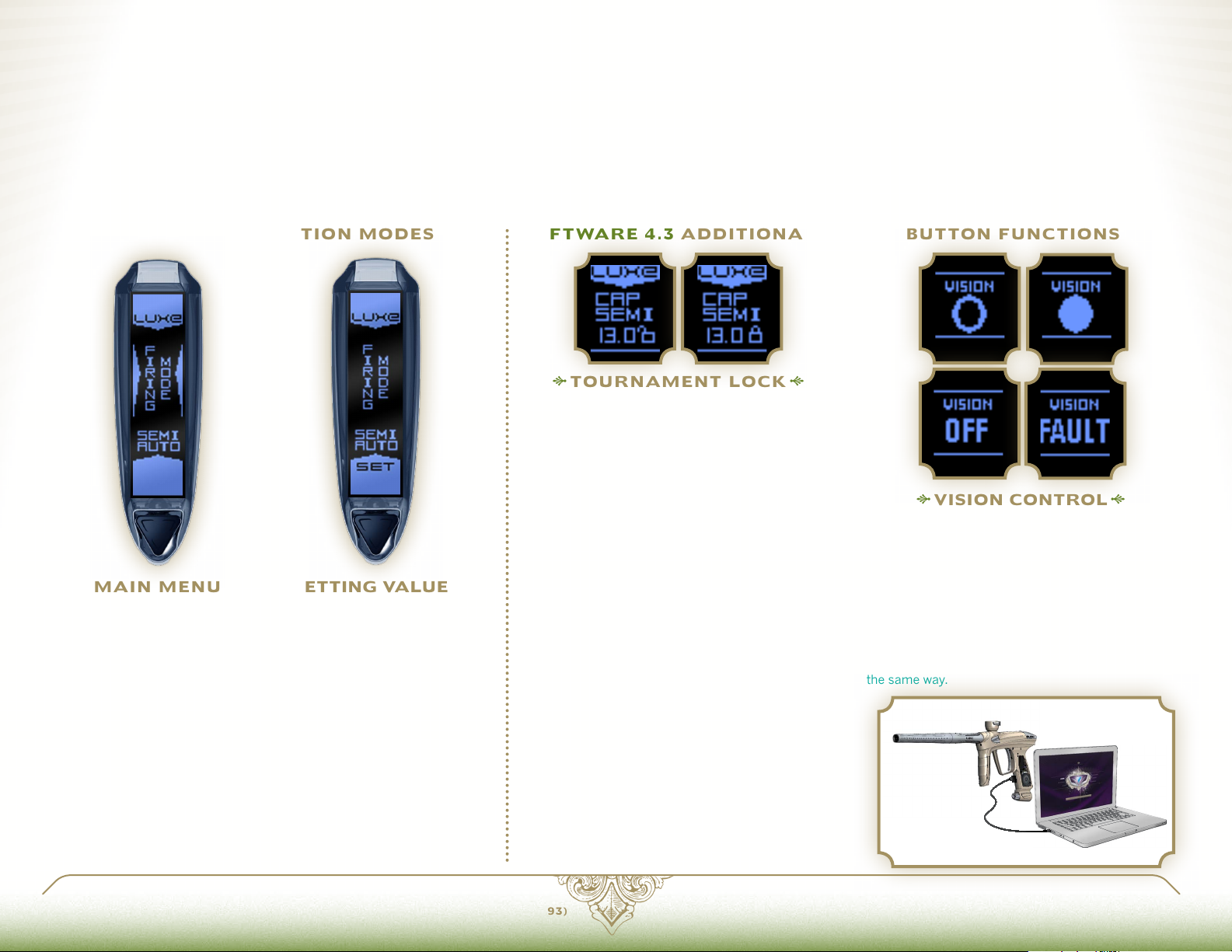
TOUrNamENT LOCk
maIN mENU
Within the main menu, you may
choose which setting you want to
check or change. The Main Menu
is indicated by tabs appearing on
the sides and bottom of the OLED
display and the Luxe® verbally
announcing that it is in the main
menu.
SOFTWa rE 4 . 4 FaCTOrY rESET
PRESSING AND HOLDING THE TRIGGER FOR approximately
5 seconds while in programming mode will result in the Luxe®
resetting all menu items to their factory default values. Factory
Reset is confirmed by 3 chirps from the speaker.
SETTING VaLUES
The word "SET" appears on the
bottom tab, and the side tabs
disappear when a menu item is
selected for setting The joystick
controller or trigger may be used
to cycle through the available
values for each setting.
FIELD LEGaL
Paintball tournaments and field operators require that
paintball markers be locked so that their velocity and
firing modes cannot be changed on the field. The lock
status is indicated by a locked or unlocked padlock in
the OLED display. When the Luxe® Tournament Lock
is on, an allen wrench must be used to remove the
marker's rubber grip, providing access to the joystick
to enter the Main Menu and make any adjustments.
When the Luxe is unlocked, turning on the Luxe while
holding the trigger back will enter the Main Menu for
adjustment using the trigger and power button. The
trigger may then be used to lock the marker once
adjustment is complete.
SOFTWa rE 4 . 5 USB INTErFaCE
INCLUDED WITH YOUR LUXE® is a USB/SATA cable,
which can be used to read or adjust the marker's
settings and re-flash the circuit board with firmware
updates, alternate language OLED firmware or alternate
voice sets. Download the latest version of the Luxe® USB
Interface software, instructions, voice files and firmware
at LuxePaintball.com.
WARNING: Do not use the USB/SATA cable with pre-2.0
Luxe® circuit boards as damage may result. Only install
Luxe® OLED firmware.
VISION CONTrOL
& Br E ECH S TaTU S
The Luxe® is equipped with a Vision break-beam
anti-chop system. The status of the Vision system
is indicated in the OLED display. An empty circle
indicates the breech is empty, while a full circle
indicates a ball has been detected. "OFF" indictates
that Vision has been de-activated, and "FAULT"
indicates an error, such as debris blocking the Vision
sensor. Vision may be deactivated by a quick doubletap of the power button. It may be turned back on
the same way.
LUXEPaINTBaLL.COm
866. 573.LUXE(5893)
PaGE 19 4.1 INTrODUCTION TO PrOGrammING
Page 19

ORIENTATION 1
HARDWARE 3
SOFTWarE 4
MAINTENANCE 5
ADV. MAINTENANCE 6
SOFTWa rE 4 . 6 FIrING mODES aND SETTINGS
WHILE REFERENCES TO PAINTBALL TOURNAMENT LEAGUE RULES ARE ACCURATE AT THE TIME OF THIS WRITING, IT IS NOT UNCOMMON FOR PAINTBALL LEAGUES TO MAKE
CHANGES TO THEIR RULES. IN ADDITION TO THE MODE CHOICE, SOME SERIES WILL REQUIRE THE USE OF THE LUXE®’S BPS LIMIT TO LIMIT MAXIMUM RATE OF FIRE. BE SURE TO
MAKE YOURSELF FAMILIAR WITH THE RULES OF ANY TOURNAMENT, SCENARIO OR GAME WHERE YOU WILL BE PLAYING, TO BE CERTAIN YOUR LUXE® SETTINGS ARE IN COMPLIANCE.
FIrING mODE
As its name implies, this setting selects one of the Luxe®'s eleven available firing modes, each of which is identified by the Luxe®
speaking the mode name and displaying it near the top of the OLED display. Settings which affect the performance of a firing mode are
stored specifically for the currently selected mode. Firing mode related settings are only available for adjustment when their associated
firing modes are selected. For example, Burst Count may only be adjusted when the firing mode is set to Burst.
AIR 2
SEmI-aUTO
UNCaPPED
This is a traditional semi-
automatic firing mode, delivering
one shot per complete trigger
pull, and it is the factory default
setting for the Luxe®. Semi-
Automatic mode is uncapped,
and the maximum rate of fire
that can be achieved in this mode
will depend on loader feed rates
and Luxe® Dwell settings. Semi-
Automatic mode is appropriate
for use at most paintball fields
and events.
SEmI-aUTO
CaPPED
While this mode functions like
Semi-Automatic, with one shot
per trigger pull, it also takes into
account the value set in the BPS
(Balls Per Second) Limit. By
activating this cap, the Luxe®'s
maximum rate of fire can be
restricted to meet the demands of
special game rules, or to handicap
experienced players against those
who are new to the sport.
NXL
NXL mode complies with the rules
of the National X-Ball League.
Initially this mode acts like Semi-
Automatic. After three trigger
pulls in quick succession, it begins
operating like Full-Automatic, firing
repeatedly while the trigger is
held down. To prevent accidental
multiple-shot firing, NXL mode
reverts to semi-automatic style
operation after a moment of no
trigger activity, at which point it
is ready to begin the cycle again.
Maximum rate of fire is capped by
the Luxe®’s BPS Limit sub-menu
setting. For use in the NXL, the BPS
Limit must be set to 13.2 or lower.
PSP 1, 2 & 3
For use under the X-Ball rules used
in the Paintball Sports Promotions
tournament series. Initially, these
mode act like Semi-Automatic until
three trigger pulls are made in
quick succession. At this point PSP
mode begins firing more than one
shot per trigger pull, as long as the
user continues to pull the trigger
at least once per second. Once the
trigger is allowed to rest for more
than a second, the cycle begins
again with one shot per trigger pull.
Each of the 3 PSP modes has a
different default BPS limit for use
in different leagues: PSP 1, 2 and 3
are preset to 10.2 BPS (PSP Pro),
12.5 BPS (PSP Divisional & CFOA)
and 15 BPS (CXBL) respectively.
Each PSP mode can be adjusted
with the BPS Limit and BPS Fine
settings.
mILLENNIUm
Similar to other series specific
modes, the Millennium mode
operates as Semi-Automatic until
the user pulls the trigger at a rate of
8 times per second or faster. At this
point, the Luxe® will begin firing
more than one shot per trigger
pull, to maximize firepower, until
the user slows below the rate of 8
trigger pulls per second, at which
point only one shot is fired per
trigger pull. For use in Millennium
events, the BPS Limit must be set
to 11.9 or lower.
Page 20

aUTO rESPONS E
Auto Response is a specialty mode
which doubles firepower by firing
both when the trigger is pulled and
when it is released. Auto Response
is affected by the BPS Limit setting.
User-definable Rebound mode allows the Luxe® to operate with ramping built to meet nearly any imaginable rule set. Rebound mode fires as semi-automatic until the set number of activation
shots (Shots To Enter) are fired at a minimum rate (Shots To Sustain) or faster, at which point the Rebound mode kicks in and fires additional shots, maximizing firepower. Once the rate of trigger
pulls drops below the Shots To Sustain setting, one shot is fired per trigger pull. To configure Rebound mode, adjust the Shots To Enter and Shots To Sustain settings.
CUSTOm rEBOUND mODE
BUrST mODE
This mode fires a burst of shots
when the trigger is pulled and held
down. The number of shots in each
burst is determined by the Burst
setting.
FULL-aUTO
In Full-Automatic mode, the Luxe®
fires repeatedly, while the trigger
is pulled and held. The rate of fire
delivered will depend on the value
of the BPS Limit setting.
DWELL
The Dwell setting determines how
long the Luxe® sends power to its
solenoid valve, which in turn affects
how long the bolt remains forward
and how much gas is released
from the fire chamber to propel
each paintball. Dwell is adjustable
from 4 to 25 milliseconds in one
millisecond increments. The default
Dwell value is 16 milliseconds,
which provides an excellent balance
between gas efficiency, speed and
reliable operation.
LUXEPaINTBaLL.COm
BPS LImIT
This setting adjusts how fast
the Luxe® can fire in all modes
except Semi-Auto. For modes
such as Capped Semi-Auto, this
setting limits the maximum rate
of fire. For modes which provide
automatic shots, like Burst and
Full-Auto, it determines the rate of
fire. BPS limit is adjusted in whole
numbers of Balls Per Second. The
value may be set from 4 BPS to 20
BPS. Default BPS and BPS Fine
values vary between firing modes.
Due to variances in the timing
of both the Luxe® and paintball
shot timers, it is recommended
that players confirm timing values
with a field's shot timer before
competition to reduce the chance
of a penalty.
866. 573.LUXE(5893)
BPS FINE
The rate of fire cap may be fine
tuned through adjustment of
the BPS Fine setting, which is
added to the BPS Limit value.
BPS Fine ranges from 0 to 9
and adds tenths of a ball per
second to the rate of fire limit.
For example, a BPS Limit of 12,
combined with a BPS Fine setting
of 8 will result in a 12.8 BPS cap
to maximize firepower under a
13 BPS tournament limit while
still providing a margin of error to
reduce the chance of a penalty.
Rebound, Auto Response and
Capped Semi modes are limited
to 20 BPS. All other modes are
limited to 15 BPS, except Semi-
Auto, which has no cap.
PaGE 21 4.5 FIrING mODES
BYPaSS BPS
Bypass BPS is an additional
rate of fire limit that is imposed
when the Vision system detects
a fault, such as paint or debris
that prevents it from working
properly. The Bypass BPS setting
can be adjusted to ensure that
the Luxe® fires slower than its
loader's slowest response rate.
Bypass BPS is adjustable between
6 and 16 bps, though the Luxe®
firmware will not allow it to be
adjusted to a value higher than the
BPS limit.
FIrST SHOT
The o-rings in the Luxe ® power core
may become set in position when
resting between shots, causing
slightly more friction than is seen
during rapid firing. This results
in the first shot of a group having
decreased velocity, also known
as First Shot Drop Off, or FSDO.
In order to overcome this friction,
the anti-bolt-stick function of the
Luxe® firmware will slightly increase
the dwell time of the first shot
in a group,. The increased dwell
will compensate for the change
in friction, keeping velocity more
consistent. The standard value for
First Shot Drop is 7 milliseconds,
and it may be adjusted between
0 and 25 milliseconds in one
millisecond increments. A setting
of 0 turns off first shot drop
DrOP
compensation.
Page 21
ORIENTATION 1
HARDWARE 3
AIR 2
SOFTWarE 4
MAINTENANCE 5
ADV. MAINTENANCE 6
FIrST SHOT
DrOP TImEr
This setting adjusts the amount of
time which the Luxe® must be at
rest between shots before activating
the anti-bolt-stick dwell increase.
Time is adjustable between 20
and 100 seconds in 20 second
increments. The default setting is 20
seconds.
TOUrNamENT
When turned on, the Tournament
Lock blocks access to the Main
Menu via the power button and
trigger, requiring use of a tool to
open the rubber grip and make
adjustments (See 4.3 ADDITIONAL
POWER BUTTON FEATURES
Tournament Lock is of f by default.
Because the Tournament Lock
may be turned on by the trigger
and power button, it is convenient
to unlock the Luxe® at a paintball
field's staging area, close its
grip, make adjustments at the
chrono station with trigger based
programming, and then lock the
marker with the Tournament Lock
before heading on to the field.
LOCk
). The
GamE
TImEr
ENaBLE
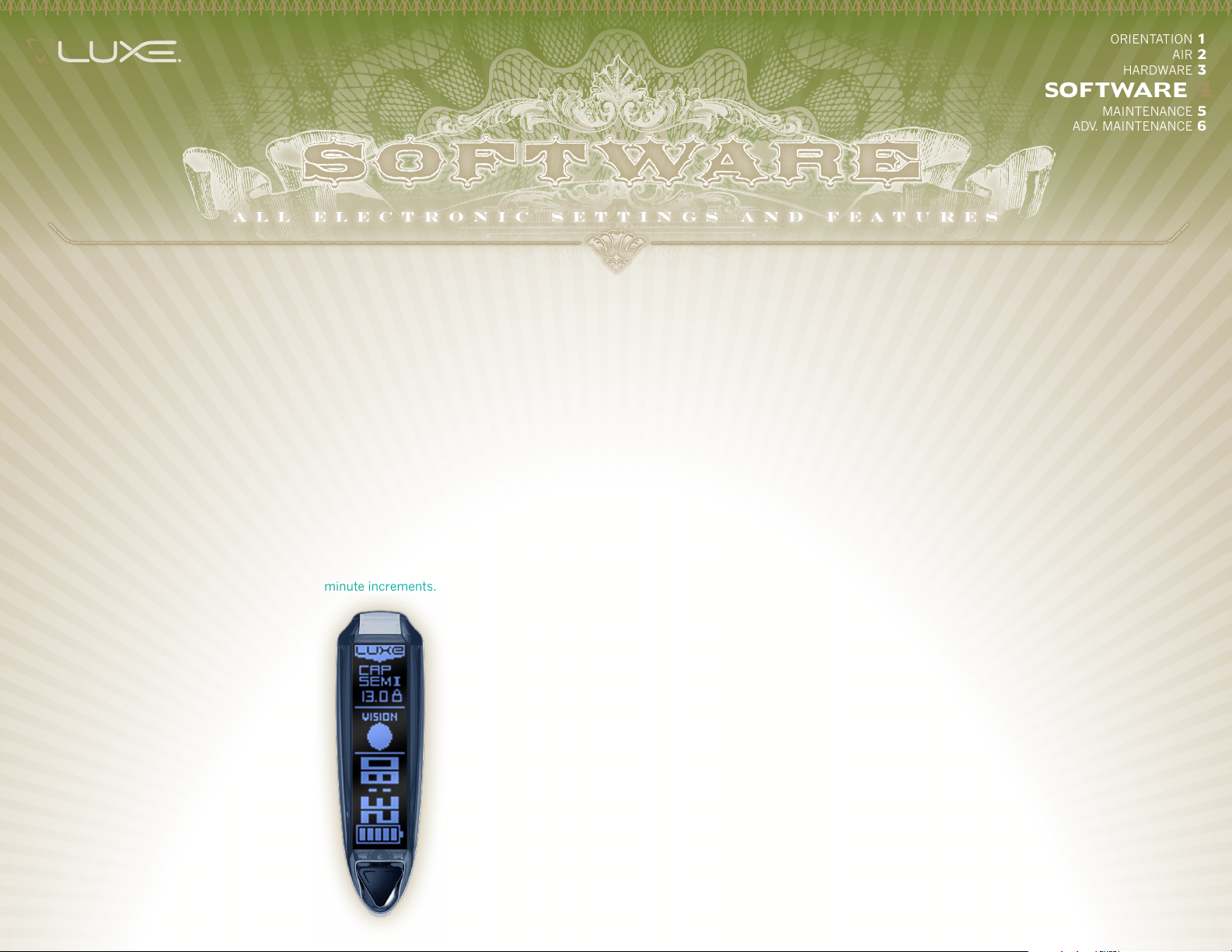
The Luxe® is equipped with a
count-down timer. When Game
Timer Enable is turned on, the
Luxe® switches to an alternate
display layout,showing the remaining
game time. The game timer begins
counting down after a single short
press of the power button.
GamE
TImEr
The Game Timer may be set
between 1 and 60 minutes, in 1
minute increments.
VISION mODE
The Vision anti-chop system in the
Luxe® may be programmed to
operate with one of two strategies.
Vision® will stop the Luxe from
firing if there is not a ball detected
in the breech when the trigger
is pulled. Forced Shot will still
provide Vision operation during
normal trigger pulls. If the trigger
is held down for a long trigger pull,
Forced Shot Vision® will fire even
if a paintball is not detected in the
breech.
TO ENTEr
Shots To Enter determines the
number of trigger pulls that must
be made at the Shots To Sustain rate
in order to activate Rebound mode
and deliver more than one shot per
trigger pull. Shots To Enter may
be adjusted from 1 to 5 and has a
default value of 3.
SHOTS TO
The trigger must be pulled repeatedly
at this rate for the Shots To Enter
number of times to activate Rebound
pulled at this rate to keep Rebound
adjustable between 2 and 10 balls
per second and has a default value
SUSTa I N
mode, and must continue to be
mode active. This setting is
of 5 BPS.
SHOTS
TrIGGEr
DEBOUNCE
When the Luxe® trigger switch is
activated, it will create a series of
very fast electrical pulses before a
complete connection is made. The
Luxe® firmware uses the Trigger
Debounce setting to determine
the difference between this switch
noise and the solid signal from
a completed trigger pull. Trigger
signals which last longer than
the Trigger Debounce value are
considered to be a valid trigger
pull. The Trigger Debounce value
is adjustable between 1 and 25
milliseconds in 1 millisecond
increments. The default value is 7
milliseconds.
LOaDEr
D E LaY
The loader delay allows time for the
paintball to seat fully in the breech,
after the Vision system has detected
it, before the Luxe fires. For forced
feed loaders, less time is necessary
than with gravity fed loaders. The
loader delay is adjustable between
0 and 15 milliseconds with a default
setting of 3.
Page 22

mECHaNICaL
DEBOUNCE
When a paintball marker's trigger
is adjusted to an extremely short
pull, it is sometimes possible for
the vibration of firing to activate the
trigger, causing a runaway condition
where one shot triggers the next
shot. The Mechanical Debounce
filtering function of the Luxe®
firmware can be set to discriminate
against these mechanical bounces,
allowing for extremely sensitive
trigger adjustment while meeting
tournament rule and field safety
requirements. Mechanical Debounce
is adjustable over a range of 0 (off)
to 10, and is off by default.
SHUTDOWN
The Luxe® will automatically turn
itself of f to conserve batter y power if
it is not fired for an extended period
of time. The Auto Shutdown Timer
is set to 30 minutes by default,
and may be adjusted from 5 to 60
minutes.
aUTO
SOFTWa rE
VErSION
Although this item cannot be
adjusted, selecting it to be set will
cause the Luxe® to read out the
version number of the currently
installed Luxe® firmware.
SPEakEr
VOLUmE
The Volume of the Luxe speaker is
adustable. Volume may be set to
1-silent, 2-quiet, or 3-loud.
English, German, Spanish and
Russian. Alternatively, different
voice sets may be loaded into voice
banks 2, 3 and 4 with the Luxe USB
interface software and cable (see
SOFTWARE 4.5.) Selecting each
voice bank allows its voice set to be
SELECT
As configured from DLX
Technology, the Luxe speaks
used.
VOICE
LUXEPaINTBaLL.COm
866. 573.LUXE(5893)
PaGE 23 4.5 FIrING mODES
Page 23
ORIENTATION 1
AIR 2
HARDWARE 3
SOFTWARE 4
maINTENaNCE 5
ADV. MAINTENANCE 6
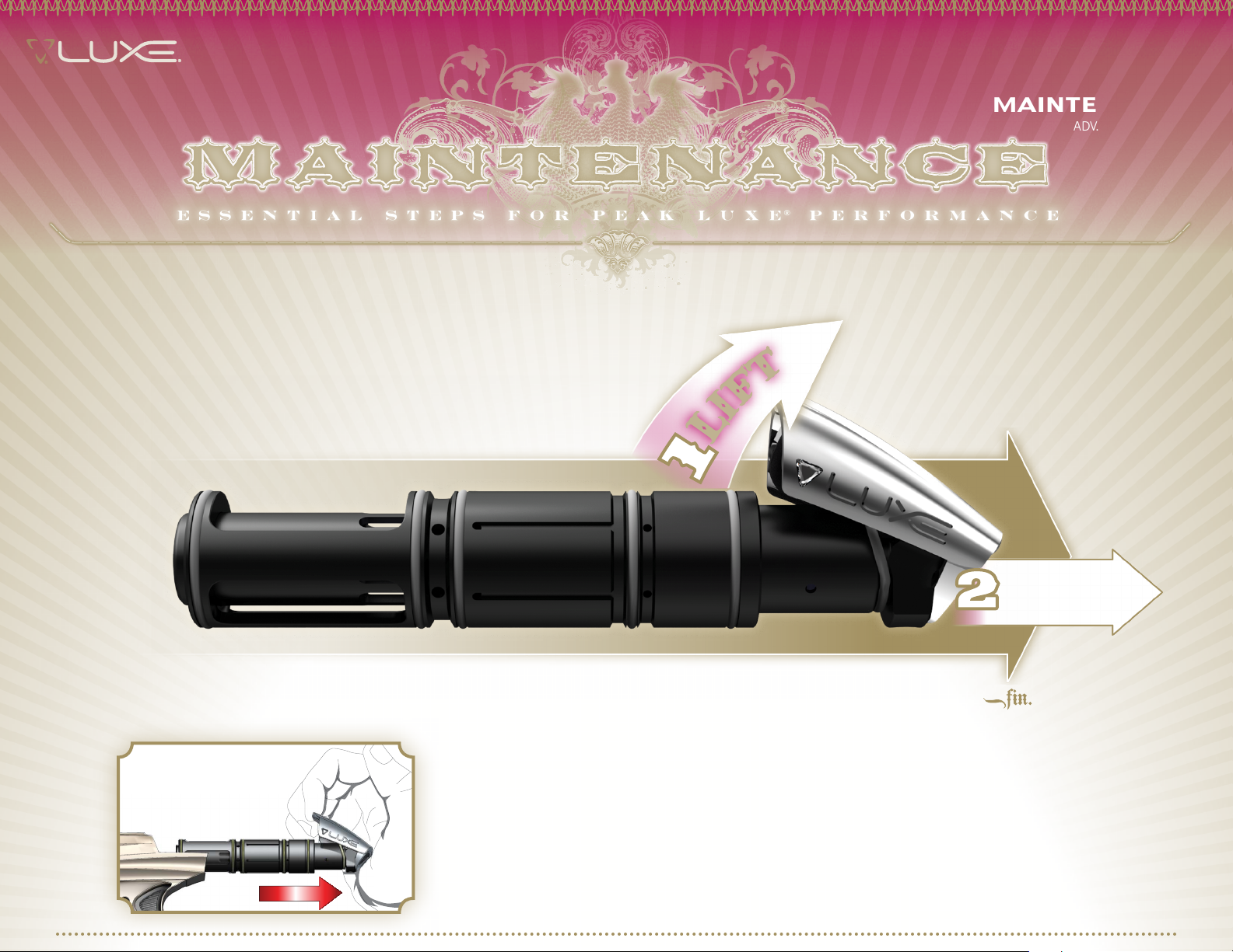
Basic Guide to RELEASING the
LUXE® POWER CORE QUICK-STRIP LATCH
THE INNOVATIVE LUXE® POWER CORE CAN BE REMOVED IN
SECONDS, NO TOOLS REQUIRED.
1
PULL
maINTENaNCE 5.1 LUXE® POWEr COrE
THE HEART OF YOUR LUXE® is the Luxe® Power Core. This single module comprises both the marker's
bolt and exhaust valve system. Its compact, tool-free design makes the Luxe® incredibly fast and simple to
maintain. The Luxe® should be disassembled and cleaned any time it shows erratic performance, becomes
contaminated with paint, dirt or other debris, or for preventative maintenance after 3 or 4 days of use.
STEP ONE UNLOaD aND DEGaS YOUr LUXE®
UNLOAD AND DEGAS YOUR LUXE® (see HARDWARE 3.2.) Turn off and or remove the gas supply. Remove the barrel
then lift the quick-strip latch at the rear of the marker and pull out the Power Core. If the Power Core has not been
removed recently it may need to be wiggled slightly to break o-ring friction.
Page 24
2
3
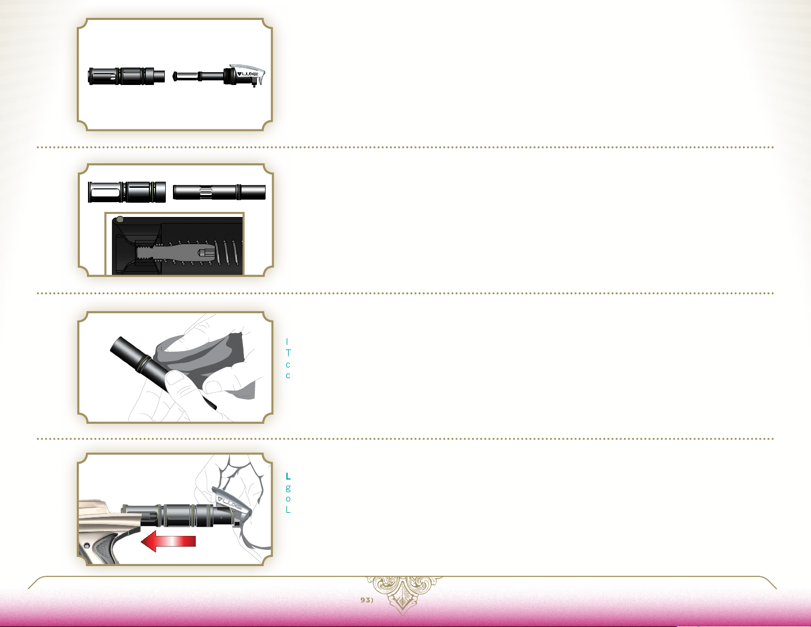
STEP TWO rEmOVE THE FIrE CHamBEr
BEGIN DISASSEMBLING THE LUXE® POWER CORE by unscrewing the fire chamber from the quick strip plug,
then slide the bolt and fire chamber off of the bolt guide.
STEP THrEE rEmOVE THE BOLT
SLIDE THE BOLT OUT of the fire chamber. Note the bolt spring mounted inside the bolt. The bolt spring
eliminates bolt stick problems (extra friction causing the bolt to move slowly or delaying bolt movement) for
improved performance in dirty or cold conditions. If the bolt spring is damaged, it may be removed and the Luxe
may safely be operated without it until a replacement can be obtained from DLX. If the Luxe is operated without
a bolt-spring, it may be necessary to increase the value of the first shot drop setting (see
spring screw in the center of the bolt spring may be removed through the back of the bolt or reinstalled using
the t-handle allen-wrench included with the Luxe. The bolt spring screw is secured with Loctite® 271 (red) or
equivalent, so the bolt face must be heated with a heat gun or lighter before removal. When reinstalling the bolt
spring screw, it must be secured in place with thread locking compound. The screw must not be over-tightened.
Its end should be just below the surface of the bolt face.
STEP FOUr CLEaN THE POWEr COrE
USING A CLEAN, SOFT CLOTH, wipe dirt, paint debris and old grease from all of the Power Core surfaces.
Inspect all o-rings and replace any which show significant signs of wear, or have rips, tears or other damage.
The windows milled into the side of the fire chamber allow easy access for inspecting internal o-rings and
changing them if necessary. Make sure the gas vents in the sides and front of the fire chamber and bolt are
clean and clear.
SOFTWARE 4.6). The bolt
4
5
LUXEPaINTBaLL.COm
STEP FIVE LUBrICaTE & rEINSErT THE POWEr COrE
LUBRICATE ALL O-RINGS WITH A LIGHT COATING of GR33SE™ marker grease. Take care to ensure that
grease is applied to inner o-rings at the front and middle of the fire chamber. Slide the bolt and fire chamber
onto the bolt guide, and screw the fire chamber to the quick-strip plug. Insert the Power Core into the rear of the
Luxe® body, with the quick strip latch lifted up. Once the Power Core is in position, close the quick strip latch.
866. 573.LUXE(5893)
PaGE 25 5.1 LUXE® POWEr COrE
Loctite is a registered trademark of Henkle
Page 25
ORIENTATION 1
AIR 2
HARDWARE 3
SOFTWARE 4
maINTENaNCE 5
ADV. MAINTENANCE 6
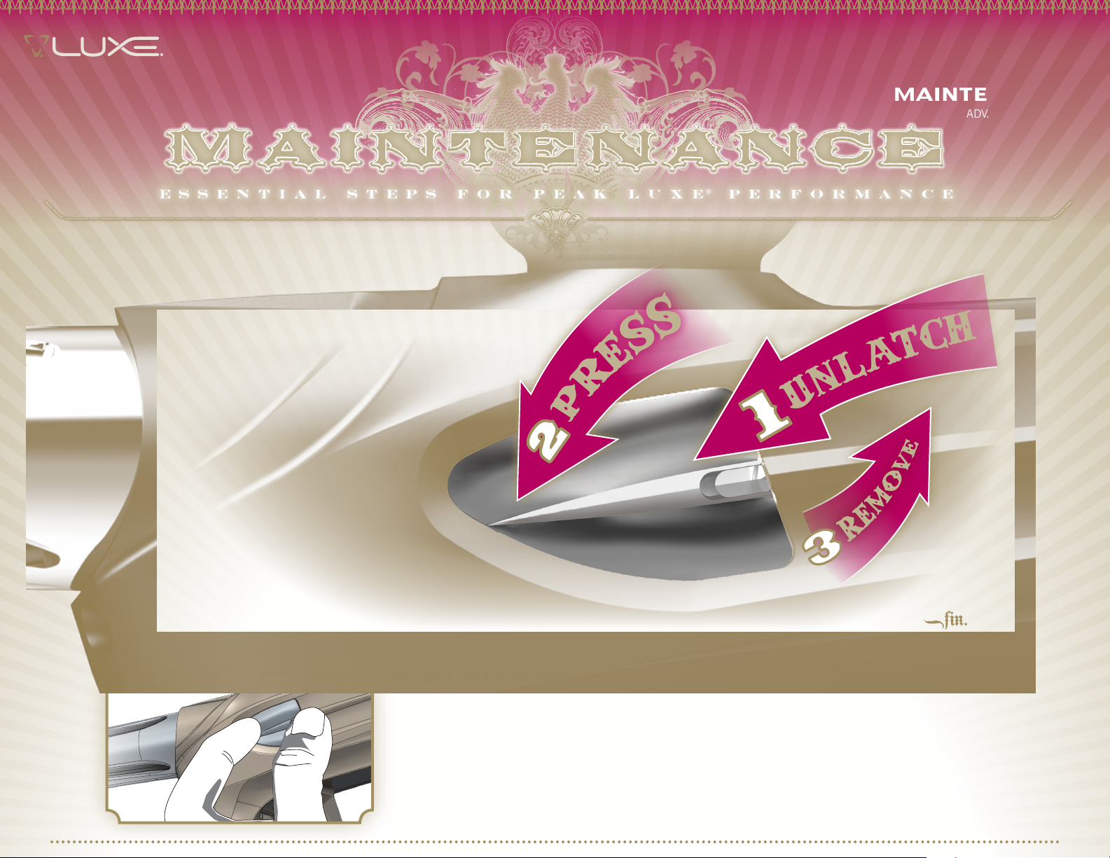
Basic Guide to REMOVING the
LUXE® QUICK-SNAP DETENT ASSEMBLIES
THE LUXE® BALL DETENT ASSEMBLIES PROVIDE INSTANT TOOL-FREE ACCESS
FOR CLEANING THE BALL DETENTS AND VISION SYSTEM IN THE FIELD.
1
maINTENaNCE 5.2 BaLL DETENTS & VISION EYES
THE LUXE® QUICK-SNAP BALL DETENT ASSEMBLIES serve both to prevent double-feeding of paint, and
to protect the Vision anti-chop eye system. Their unique magnetic and physical latch systems keeps them
secure, while allowing for easy tool-free maintenance. There is a ball detent assembly on each side of the
marker, and both should be cleaned and inspected in the same manner.
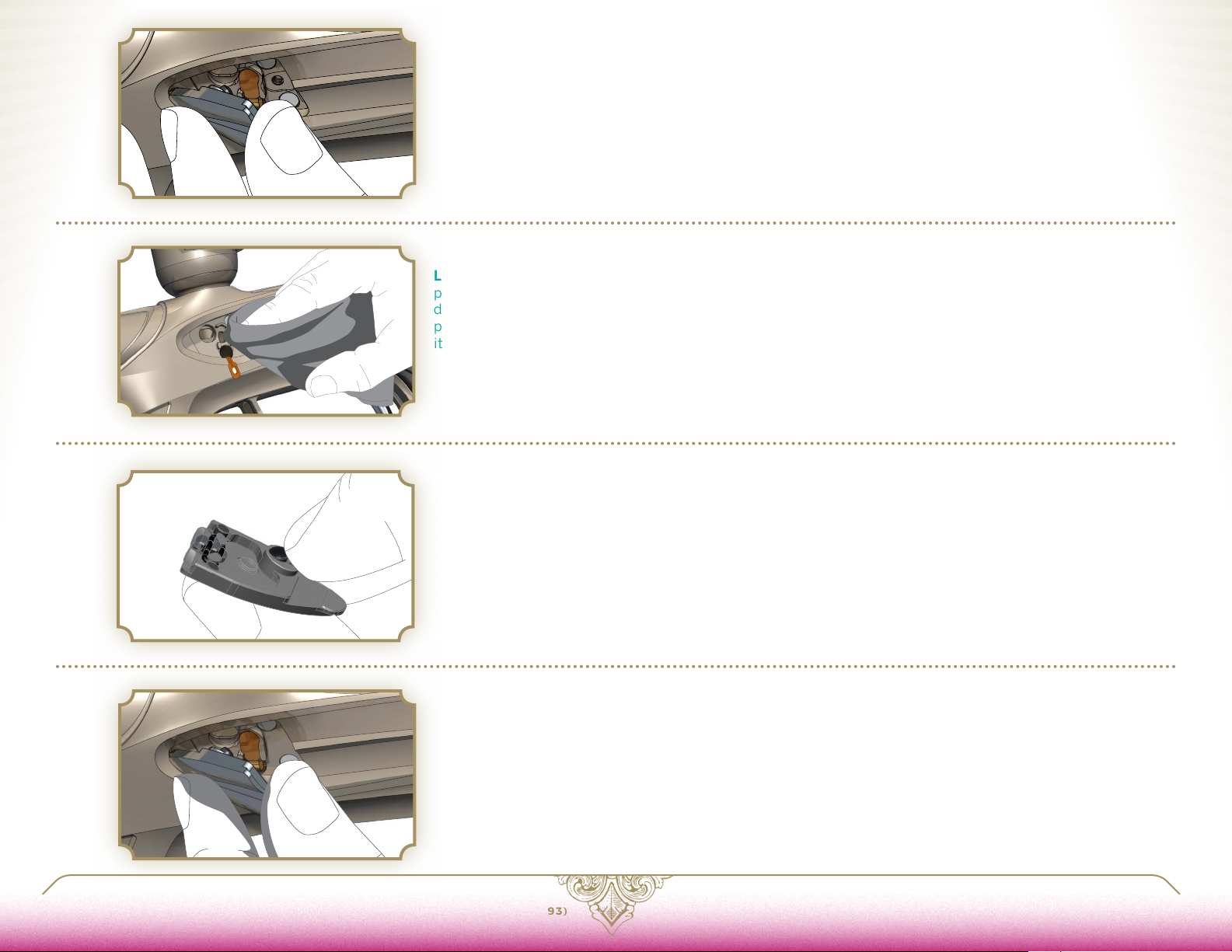
STEP ONE PrESS DETENT aSSEmBLY
PRESS ON THE FORWARD POINT OF THE BALL DETENT ASSEMBLY while sliding the Quick-Snap latch
forward. This will separate the magnets at the rear, pushing the assembly’s back edge out from the Luxe®
body.
Page 26
2
3
STEP TWO rEmOVE DETENT aSSEmBLY
GRASP THE BALL DETENT ASSEMBLY from the rear, and lift outward, away from the Luxe® body.
STEP THrEE CLEaN VISION EYE POCkET
LIFT OUT THE VISION EYE from its pocket in the Luxe® body. Using a soft cloth or cotton swab, clean any
paint, debris or grease from the passage between the eye pocket and the breech, or from the eye itself. If
debris buildup is severe, use a cotton swab dampened with rubbing alcohol for cleaning the Vision eye and its
pocket and allow them to dry completely before proceeding. Take care not to scratch the Vision eye or strain
its flex-strip circuit. Gently re-seat the Vision eye in its pocket, with its emitter or sensor facing inward.
STEP FOUr INSPECT BaLL DETENT PLUNGEr
CLEAN AND INSPECT THE BALL DETENT PLUNGER in the ball detent assembly. It should move freely when
pressed in and released. If the plunger or the Quick-Strip latch tension o-ring show significant signs of wear or
binding, replace them following the instructions in
ADVANCED MAINTENANCE 6.3.
4
5
LUXEPaINTBaLL.COm
STEP FIVE rEINSTaLL DETENT
REINSERT THE BALL DETENT ASSEMBLY by hooking its pointed edge into the front side of its pocket in the
Luxe® body. Then angle the rear into place, allowing the rare-earth magnets to grip and secure it in place. Make
sure that the latch has clicked into the locked position. Test the latch by pressing on the forward point of the
detent assembly to make sure it does not pop out.
866. 573.LUXE(5893)
PaGE 27 5.2 BaLL DETENTS & VISION EYES
Page 27
ORIENTATION 1
HARDWARE 3
SOFTWARE 4
MAINTENANCE 5
aDV. maINTENaNCE 6
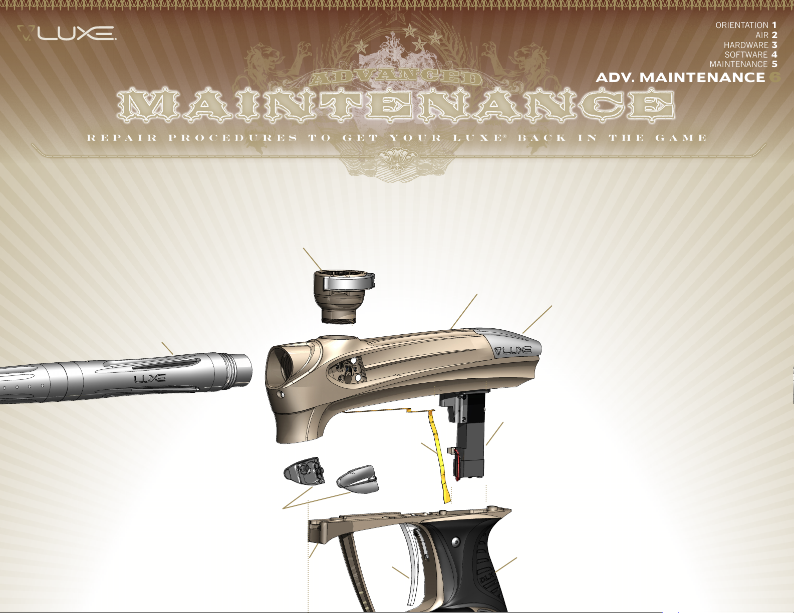
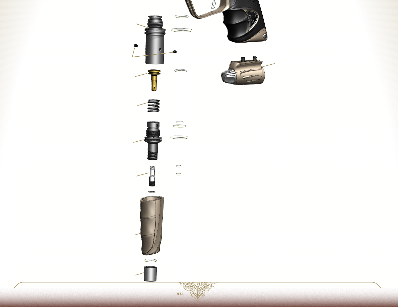
aDVaNCED maINTENaNCE 6.1 INTrODUCTION
UNDER NORMAL CONDITIONS, YOUR LUXE® should only need the basic maintenance procedures performed. This advanced maintenance section is provided to give
you additional familiarity with the Luxe®. If you do not feel comfortable with going beyond regular maintenance, see your Authorized Luxe® dealer for support.
1
3
4
AIR 2
2
7
6
5
10
8
9
Page 28
13
14
16
12
15
17
11
maIN LUXE® markEr COmPONENTS
10
11
12
13
14
15
16
17
18
19
CLAMPING FEEDNECK
1
LUX E® 3-PI EC E BA R REL SYSTEM
2
BODY
3
LUX E® POWER C ORE
4
LUX E® QUIC K-S NA P DETENT A SSE MBLI E S
5
VISION E YE RI BB ON
6
SOLENOID VALVE & MA NIFOLD
7
GRI P FRA M E
8
TRIGGER
9
GRIP
VE NTING ON/OFF BOTTOM-LI NE
UPPER V E RTICAL R EGUL ATOR HOUSI NG
LOC K SC REWS
PRE S SUR E CON TROL PISTON
VE RTICAL R E GULATOR SPR ING
LOWE R V ERTICA L REGUL ATOR HOUSING
VE LOCITY A DJ USTE R
VE RTICAL R E GULATOR COVER
COVER LOCK
18
19
LUXEPaINTBaLL.COm
866. 573.LUXE(5893)
PaGE 29 6.1 aDVaNCED maINTENaNCE INTrODUCTION
Page 29
1
ORIENTATION 1
AIR 2
HARDWARE 3
SOFTWARE 4
MAINTENANCE 5
aDV. maINTENaNCE 6
aDVaNCED maINTENaNCE 6.2 SErVICING THE VErTICaL rEGULaTOr
SERVICE AND ADJUSTMENTS TO THE REGULATOR WILL CAUSE CHANGES IN ITS OUTPUT PRESSURE. RE-ADJUST THE
REGULATOR FOR THE CORRECT VELOCITY USING A CHRONOGRAPH AS DESCRIBED IN THE MARKER’S MANUAL.
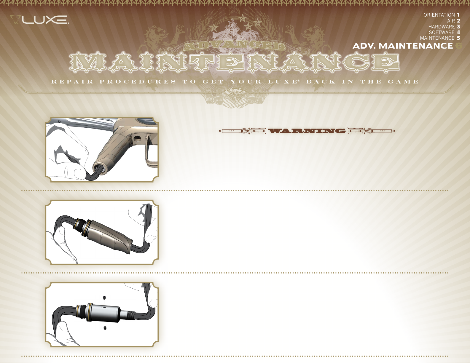
STEP ONE rEmOVE rEGULaTOr FrOm aSa
WITH THE LUXE® UNLOADED AND DEGASSED, use a 5/16-inch allen wrench to unscrew the Luxe® vertical
regulator from the bi-directional ASA. Hold the regulator cover to prevent it from turning with the regulator.
Inspect and clean the o-ring at the top of the regulator, then lubricate it with GR33SE™.
2
3
STEP TWO rEmOVE rEGULaTOr COVEr
INSERT A 3/8-INCH ALLEN WRENCH into the top of the Luxe® regulator, and a 3/8-inch allen wrench into the
cover lock at the bottom. Turn the allen wrenches counter-clockwise relative to one another to unscrew the cover
lock, and slide the Luxe® regulator out of its cover. Clean and inspect both o-rings on the bi-directional ASA
fitting at the top of the regulator, and replace if damaged. Lubricate both o-rings with GR33SE™.
STEP THrEE DISaSSEmBLE rEGULaTOr HOUSING
USE A 5/64-INCH ALLEN WRENCH to remove the two lock-screws from the sides of the Luxe® regulator.
Using a 3/8-inch allen wrench in the top regulator housing, insert a 5/16-inch allen wrench into the lower
regulator housing and turn the two counter-clockwise relative to one another. Remove the lower regulator
housing from the upper.
Page 30
4
5
STEP FOUr PrESSUrE CONTrOL PISTON
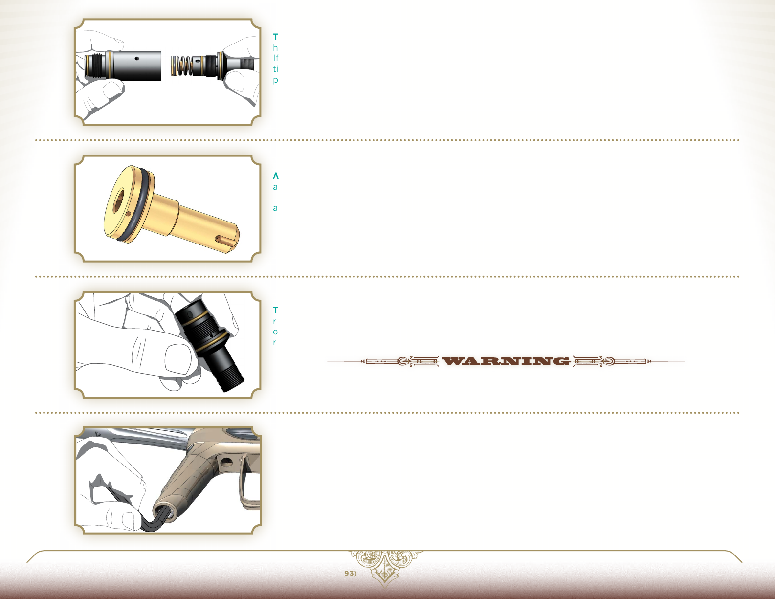
THE BRASS PRESSURE CONTROL PISTON and regulator spring may come out with the lower regulator
housing. If they do, the pressure control piston may be pulled out of the lower regulator housing by hand.
If the pressure control piston remains in the regulator housing, the regulator spring can be dropped out by
tilting the upper regulator housing, and a 5/16-inch allen wrench may be used to push the pressure control
piston out from the top.
STEP FIVE INSPECT SEaLS aND rEGULaTOr HOUSING
AT THIS LEVEL OF DISASSEMBLY, the pressure control piston seal and regulator housings may be inspected,
and cleaned with a soft cloth or cotton swab. If the piston seal shows signs of excessive wear or damage, it
must be replaced. Lightly lubricate all o-rings with GR33SE™ for reassembly. For normal maintenance this is
all that must be done.
STEP SIX VELOCITY aDJUSTEr
THE VELOCITY ADJUSTER SHOULD only be removed if leaking. Using a narrow pair of snap-ring pliers,
remove its lock ring, then unscrew it clockwise (the velocity adjuster is left-hand threaded) out the bottom
of the lower regulator housing. Clean, inspect, lubricate and if necessary replace the adjuster's o-rings, then
reinstall it with the reverse procedure.
6
7
LUXEPaINTBaLL.COm
PARTS OF THE LUXE® INTEGRATED AIR VERTICAL REGULATOR USE LEFT-HANDED THREADS. THESE PARTS MUST
BE TURNED COUNTER-CLOCKWISE TO SCREW THEM IN AND CLOCKWISE TO UNSCREW THEM—THE OPPOSITE
DIRECTION OF NORMAL SCREWS.
STEP SEVEN rEaSSEmBLE rEGULaTOr
REASSEMBLY IS PERFORMED in the reverse order of disassembly. Insert the pressure control piston into the
upper regulator housing, followed by the regulator spring. Screw the lower regulator housing into the upper
housing. Look in the lock screw holes to make sure the two halves are aligned properly. Reinstall the lock
screws, securing them with blue Loctite® 242. When the housing halves are properly aligned, the lock screws
will be able to sit flush with the body. If they do not sit flush, remove them and realign the body halves. Do not
over-tighten the lock screws. Using a 5/16-inch allen wrench from the bottom, screw the regulator into the bidirectional ASA then slide the regulator cover in place and secure it with the cover lock.
866. 573.LUXE(5893)
PaGE 31 6.2 SErVICING THE VErTICaL rEGULaTOr
Page 31
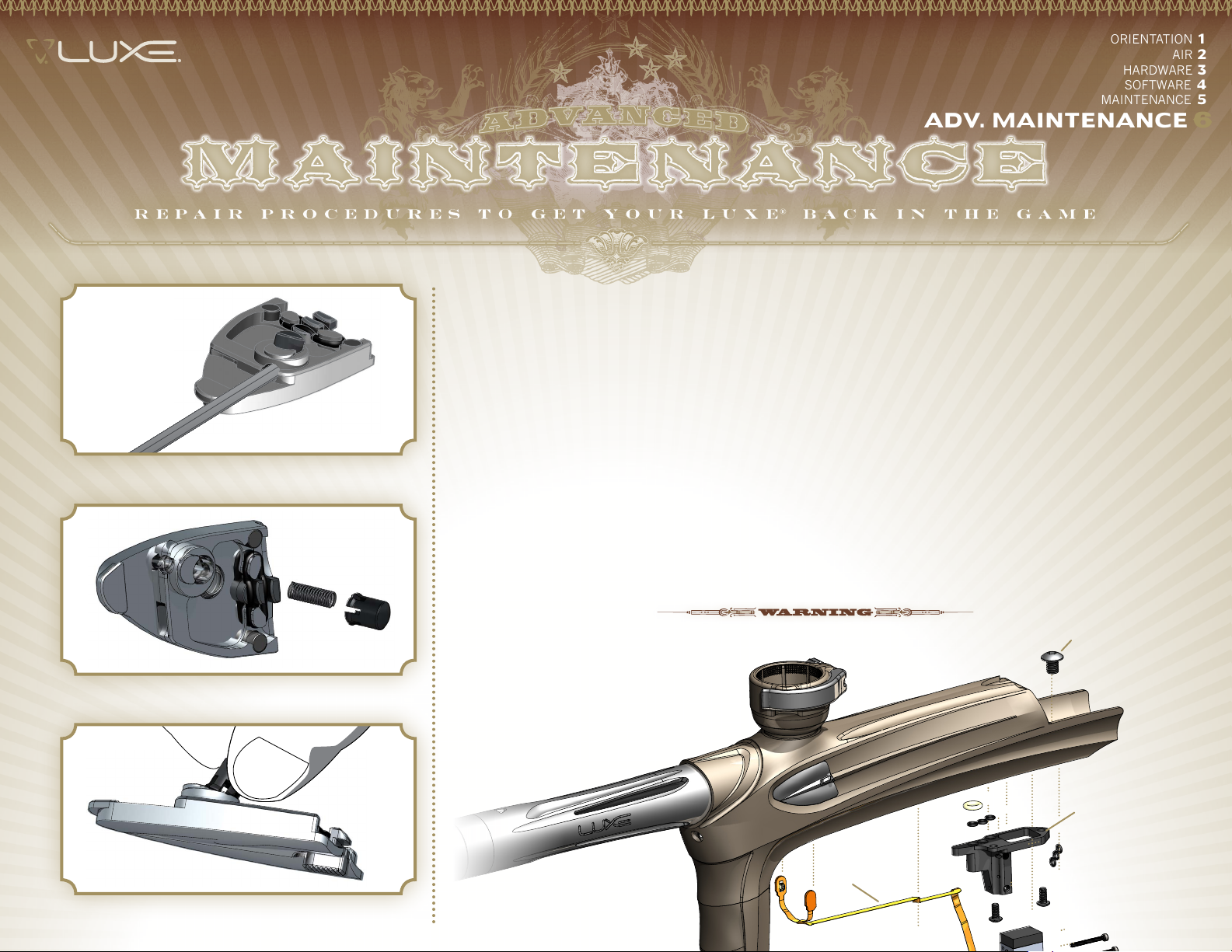
FIG. 1
ORIENTATION 1
AIR 2
HARDWARE 3
SOFTWARE 4
MAINTENANCE 5
aDV. maINTENaNCE 6
aDVaNCED maINTENaNCE 6.3 BaLL DETENT aSSEmBLIES
IF THE BALL DETENT PLUNGER OR ITS SPRING are worn and need replacing, this is a relatively simple
task. Remove the ball detent assemblies from the Luxe®, and press their plungers in and out. You should
see one of the plunger's fingers moving back and forth across the detent release hole.
Take your 1/16-inch allen wrench, and reach it into the release hole [FIG. 1.] Use the allen wrench to pry
outward on the backside of the ball detent plunger. Once the plunger is popped loose, you may pull it out
of the ball detent cover with your fingers or a pair of needle-nosed pliers. You will probably damage the ball
detent spring in the process, and for this reason it is normal to replace both the plunger and spring at the
same time. If you are careful to not put the wrench in any further than is needed to pry against the closest
edge of the plunger, you can avoid damage to the ball detent spring. Also check the Detent Assembly
tension spring to make sure it is properly seated. Replace if bent or damaged. If, necessary the Quick-Strip
latch may be removed for cleaning by first removing its tension garter spring. Replace the spring if worn.
FIG. 2
FIG. 3
Carefully clean the ball detent cover with rubbing alcohol and a cotton swab. Install the new ball detent
plunger, with its spring beneath it, into the ball detent cover [FIG 2.] You will need to pinch the plunger’s
fingers inward and wiggle it until it presses inside the cover and latches into place [FIG. 3.] Be careful, and
make sure you are doing this in a clean work area—if you slip, the spring can jump away from you, and it is
much easier to find on a clean work table.
1
THE BALL DETENT PLUNGERS ARE
MADE OF SELF-LUBRICATING MATE-
RIAL. DO NOT USE GREASE,
OIL OR OTHER LUBRICANTS ON
THEM.
2
3
Page 32
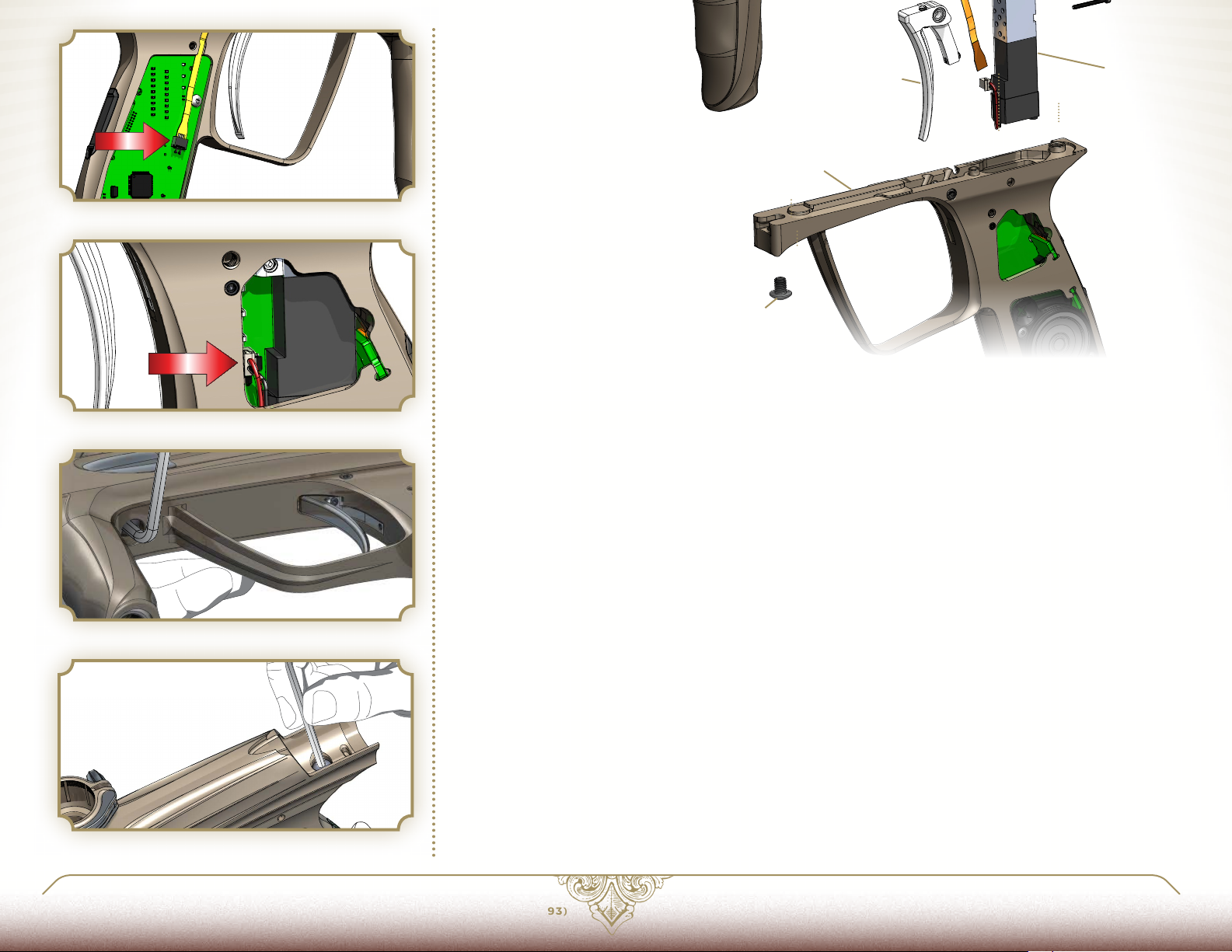
FIG. 4
FIG. 5
4
5
6
maIN GrIP Fr amE COmP ONENTS
aDVaNCED maINTENaNCE 6.4 GrIP FramE rEmOVaL
REMOVING THE LUXE® GRIP FRAME IS NOT a part of regular maintenance. It should only need to be
performed if replacing the anti-chop Vision eyes or solenoid valve. It is recommended that this procedure
be performed by a Certified Luxe® Technician, as re-assembly errors may cause leaks in the Integrated Air
system or damage to the Luxe® body.
To remove the grip frame first unload and degas the Luxe®. Next use a 5/64-inch allen wrench to remove
all four grip screws and the flexible rubber grip. Unplug both the flexible Vision eye ribbon [FIG. 4] and the
solenoid valve [FIG. 5.]
GRI P FRA M E SC REWS
1
VISION E YE STR IP
2
SOLE NOID M ANIFOLD
3
SOL EN OI D VALV E
4
TRIGGER
5
GRI P FRA M E
6
1
FIG. 6
FIG. 7
LUXEPaINTBaLL.COm
Use a 1/8-inch allen wrench to loosen the forward grip frame screw [FIG. 6.] Use the same allen wrench to
loosen the rear grip frame screw from the top [FIG. 7.]
While carefully supporting both the Luxe® body and grip frame, completely remove the front and rear grip
frame screws. Next, carefully lift the receiver apart from the grip frame. Take care not to snag the solenoid
valve connector, and notice how the Vision eye cable is routed through slots in the bottom of the receiver.
With the receiver and grip frame apart, the solenoid valve and solenoid manifold may be removed from the
Luxe® receiver by removing their respective screws. A 1.5mm allen wrench will be required to remove the
screws holding the solenoid valve to its manifold. Once the solenoid manifold is separated from the receiver, the Vision eye strip is free to be lifted out of its channel in the Luxe® body. With the ball detent assemblies removed (see MAINTENANCE 5.2) the eyes may be lifted out of their pockets and passed down through
their openings in the receiver.
Reassembly is performed in the reverse order of disassembly. It is critical to ensure that the solenoid valve
wires and Vision eye flex strip are routed properly, and do not become bent or pinched. The sensor and
emitter ends of the Vision eye flex strip are keyed with a notched corner to ensure that they are placed on
the correct side of the marker. When plugging the Vision flex strip into the Luxe® circuit board, be certain
the side with the shiny metal contact surfaces faces outward, away from the circuit board. The forward and
rear grip frame screws must be snug, but not overtightened. Over-tightening the solenoid valve or solenoid
manifold screws may cause permanent damage.
866. 573.LUXE(5893)
PaGE 33 6.3 BaLL DETENT aSSEmBLIES
Page 33
ORIENTATION 1
HARDWARE 3
SOFTWARE 4
MAINTENANCE 5
AIR 2
aDV. maINTENaNCE 6
1
maIN LUXE® P OWEr COrE COmP ONENTS
QUICK-STRIP LATCH COVER
1
LATC H COVER SC REW
2
LATCH RETURN O-RING
3
QUICK-STRIP LATCH
4
PIVOT PIN
5
8
10
DEG AS SING VALVE CORE PI N
6
QU ICK- STRI P P LUG
7
FIRING CHAMBER
8
BOLT
9
BOLT GU IDE
10
9
aDVaNCED maINTENaNCE 6.5 QUICk-STrIP PLUG DISaSSEmBLY
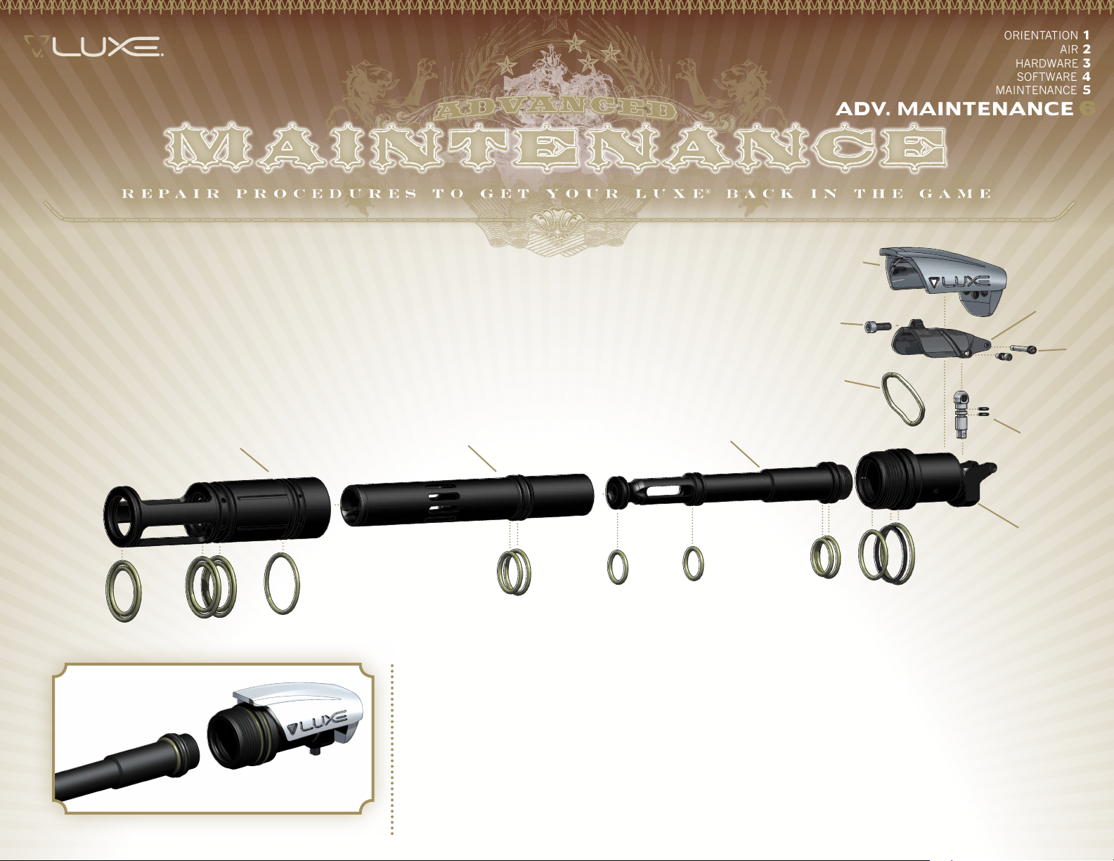
IT MAY OCCASIONALLY BECOME NECESSARY to disassemble the Luxe® Power Core’s quick strip plug.
First, remove and disassemble the Power Core, following the instructions in MAINTENANCE 5.1.
2
3
4
5
6
7
FIG. 1
Unscrew the bolt guide from the quick strip plug and remove it [FIG. 1.] Lift the quick-strip latch and use a
3-32-inch allen wrench to remove the screw that secures its cover [FIG. 2.] The quick-strip latch cover will
then lift off of the latch. You will now be able to see the latch return o-ring. This o-ring does not create a
seal, instead it acts as a spring to keep the quick-strip latch closed. It may be removed with an o-ring pick
[FIG. 3.] Using a 0.050-inch allen-wrench, unscrew and remove the quick-strip latch pivot pin from the rear
of the quick-strip plug [FIG. 4.]
Page 34
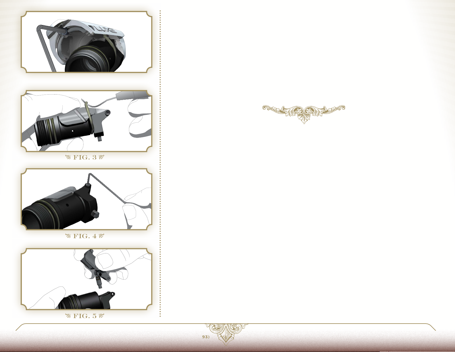
FIG. 2
FIG. 3
With the pin removed, the latch can be lifted upward, exposing the degassing valve core and its black o-rings
[FIG. 5.] If the quick-strip latch was closed while your Luxe® was still connected to a gas supply, and has
developed a leak, these are the o-rings likely to have been damaged. To replace, simply remove them with an
o-ring pick and slide new o-rings into place, lubricating them lightly with GR33SE™.
The degassing valve core pin also serves as the locking pin which secures the Power Core in the Luxe® body.
Inspect the lower end of the degassing valve core pin for signs of wear or bending, its edges should be
square and undamaged.
Reassembly of the Power Core is performed in reverse of disassembly. Lower the cleaned and GR33SE™
lubricated degassing valve core down into the quick-strip plug, and align the rear of the quick-strip latch.
Slide the quick-strip latch pivot pin into place, and screw it in, taking care not to over-tighten. Use a small
amount of Blue Loctite® 242 or equivalent threadlocker (if unavailable, clear nail polish may substitute) on
the threads of the latch cover screw and pivot pin. Lift up the latch, set the latch cover in place, and secure
it with its screw. Next screw the bolt guide back into the quick-strip plug, and re-assemble the Power Core.
FIG. 4
FIG. 5
LUXEPaINTBaLL.COm
866. 573.LUXE(5893)
PaGE 35 6.5 QUICk-STrIP PLUG DISaSSEmBLY
Page 35
aDV. maINTENaNCE 6
aDVaNCED maINTENaNCE 6.6 TrOUBLESHOOTING
ORIENTATION 1
AIR 2
HARDWARE 3
SOFTWARE 4
MAINTENANCE 5
FIG. 1
FIG. 2
PrOBLEm
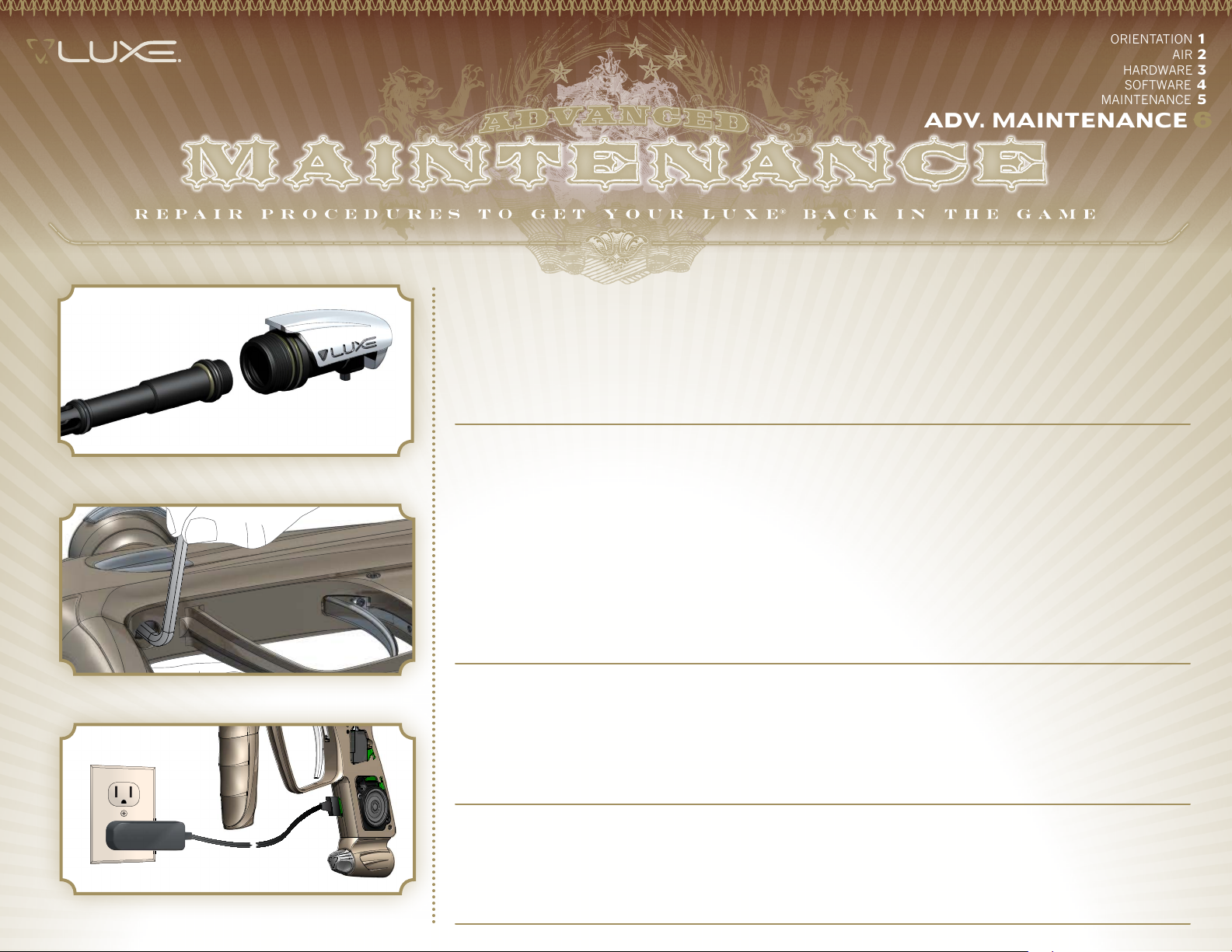
AFTER ACCIDENTALLY CLOSING THE QUICKSTRIP LATCH, WHILE THE MARKER’S HPA SYSTEM
WAS TURNED ON, THE LUXE® HAS A SLOW,
CONTINUOUS LEAK.
LUXE® POWER CORE WILL DEGAS, BUT CATCHES
ON SOMETHING AND WILL NOT SLIDE OUT.
LUXE® WILL NOT TURN ON WHEN POWER
BUTTON IS DOUBLE-PRESSED.
SOLUTION
Disassemble the Quick Strip Plug [FIG. 1,]
following the instructions in this manual, and
replace the damaged degassing core o-rings
(see ADVANCED MAINTENANCE 6.5.)
If the rear grip frame screw has become loose
it may catch on the Power Core. With the Luxe®
unloaded and degassed, loosen the front grip frame
screw [FIG. 2,] two or three turns, then pull the grip
frame away from the body, creating a slight gap
between them. This will pull the rear grip frame
screw down and out of the way, allowing for removal
of the Power Core. Re-tighten both grip frame screws.
If this is a recurring problem, you may wish to
secure the rear grip frame screw with a small
amount of Loctite® 242 (blue) or equivalent threadlocking compound.
Recharge the Luxe® battery [FIG. 3] following the
instructions in this manual (see HARDWARE 3.6.)
Following the battery replacement instructions
(see HARDWARE 3.6,) ensure that the battery is
installed and connected securely to the Luxe®
circuit board.
FIG. 3
FIRST SHOT FIRED HAS LOW VELOCITY
BUT STABILIZES WITH FOLLOWING SHOTS
(FIRST SHOT DROP-OFF.)
Clean, inspect and lubricate the Luxe® Power
Core and bolt spring (see MAINTENANCE 5.1.)
Increase FSD Compensation setting
(see SOFT WARE 4.6)
Loctite is a registered trademark of Henkle
Page 36
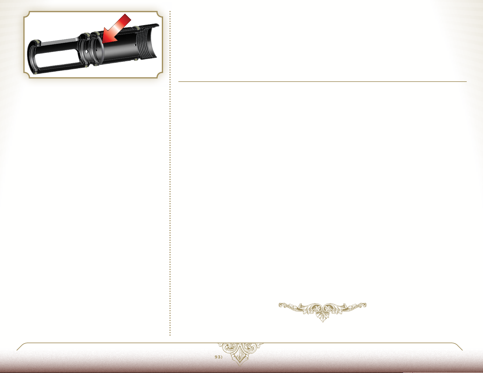
FIG. 4
LUXE® WILL TURN ON AND MAKES PUFFING
SOUND WHEN TRIGGER PULLED BUT WILL
NOT FIRE.
Make sure that the Dwell setting is set to the default
value or higher (see SOF TWARE 4 .6.)
Clean the Power Core, and replace and lubricate
the fire chamber's inner o-rings.
(see MAINTENANCE 5.1.)
Replace the o-ring indicated in [FIG 4.]
VELOCITY DROPS OFF DURING RAPID FIRE.
aDVaNCED maINTENaNCE 6.7 LImITED WarraNTY
WARRANTY SUPPORT AND SERVICE FOR DLX TECHNOLOGY GROUP PRODUCTS IS PROVIDED BY
FACTORY TRAINED SERVICE TECHNICIANS AT LUXE® AUTHORIZED DEALERS.
DLX TECHNOLOGY GROUP WARRANTS FOR ONE (1) YEAR TO INITIAL RETAIL PURCHASER THAT
THE PAINTBALL MARKER AND REGULATOR COMPONENTS ARE FREE FROM DEFECTS IN MATERIALS
AND WORKMANSHIP. THE VALVE ASSEMBLY AND SOLENOID ARE WARRANTED FOR SIX (6) MONTHS.
DISPOSABLE PARTS (BATTERIES, O-RINGS, SEALS, ETC.) ARE NOT WARRANTED. ELECTRONIC
COMPONENTS ARE WARRANTED FOR SIX MONTHS WITHOUT THE INCLUSION OF INSTALLATION AND
LABOR CHARGES.
Clean, inspect and lubricate the Luxe® Power Core
(see MAINTENANCE 5.1.)
LUXEPaINTBaLL.COm
THIS WARRANTY DOES NOT COVER SURFACE DAMAGES (SCRATCHES AND NICKS), MISUSE, IMPROPER
DISASSEMBLY AND RE-ASSEMBLY, ATTEMPTS MADE TO DRILL HOLES OR REMOVE METAL FROM THE
EXTERNAL SURFACES WHICH COULD DEGRADE PERFORMANCE AND REDUCE PRESSURE SAFETY
FACTORS OF THE MARKER. DO NOT MAKE CHANGES TO THE BASIC MARKER PARTS WITHOUT
WRITTEN APPROVAL. THE ONLY AUTHORIZED LUBRICANT FOR THE MARKER IS GR33SE™ LUBRICANT.
USE OF ANY OTHER LUBRICANT COULD RESULT IN VOIDING YOUR WARRANTY. PAINTBALL MARKERS
ARE NON-REFUNDABLE.
THIS WARRANTY IS LIMITED TO REPAIR OR REPLACEMENT OF DEFECTIVE PARTS WITH THE
CUSTOMER RESPONSIBLE FOR TRANSPORTING THE PRODUCT TO AND FROM THE LUXE®
AUTHORIZED DEALER. THIS WARRANTY IS EFFECTIVE ONLY IF THE CUSTOMER RETURNS THE
WARRANTY REGISTRATION CARD ENCLOSED WITH THE MARKER. THE WARRANTY IS NONTRANSFERABLE. DO NOT ATTEMPT TO ALTER THE TRIGGER ASSEMBLY IN ANY WAY, AS THIS WILL
VOID YOUR DLX TECHNOLOGY GROUP WARRANTY. TRIGGER ALTERATION OF ANY KIND MAY RESULT
IN SERIOUS INJURY.
866. 573.LUXE(5893)
PaGE 37 6.6 TrOUBLESHOOTING
 Loading...