

Page 1
DLS ZM1, Z-match
General
DLS Z-match is an impedance-matching transformer for
speaker loads.
It can be used for transforming up or down the output
voltage from a car amplifier to the speaker/speakers.
You may have had the problem that you want to connect
two 4 ohm subwoofers in br idge mode to an amplifier.
Since most amplifiers are 2 ohm stable this is impossible
without destroying the amplifier. But with a Z-match you
ca solve this problem easily.
Transforming up
If a voltage is transformed up the amplifier normally
produces more power. This relation is useful if the speaker/speakers has a high impedance, and the amplifier
tolerates low impedances.
With a DLS Z-match the voltage can be transformed up
with +41%, +100% or +182%.
It can be described that the amplifier senses a lowered
speaker impedance to half, to 1/4 or to 1/8.
Transforming down
If the voltage is transformed down the amplifiers output
impedance better matches a low-ohm load, for example
several speakers connected in parallel.
Here the transformer is used backwards and can transform the voltage down to 70%, 50% or 35% of the full
voltage. The amplifier senses an increase of the speaker
limpedance to 2 times, 4 times or 8 times.
By using different combinations the impedance can be
changed in more than 25 different steps.
1. Output impedance of the amplifier
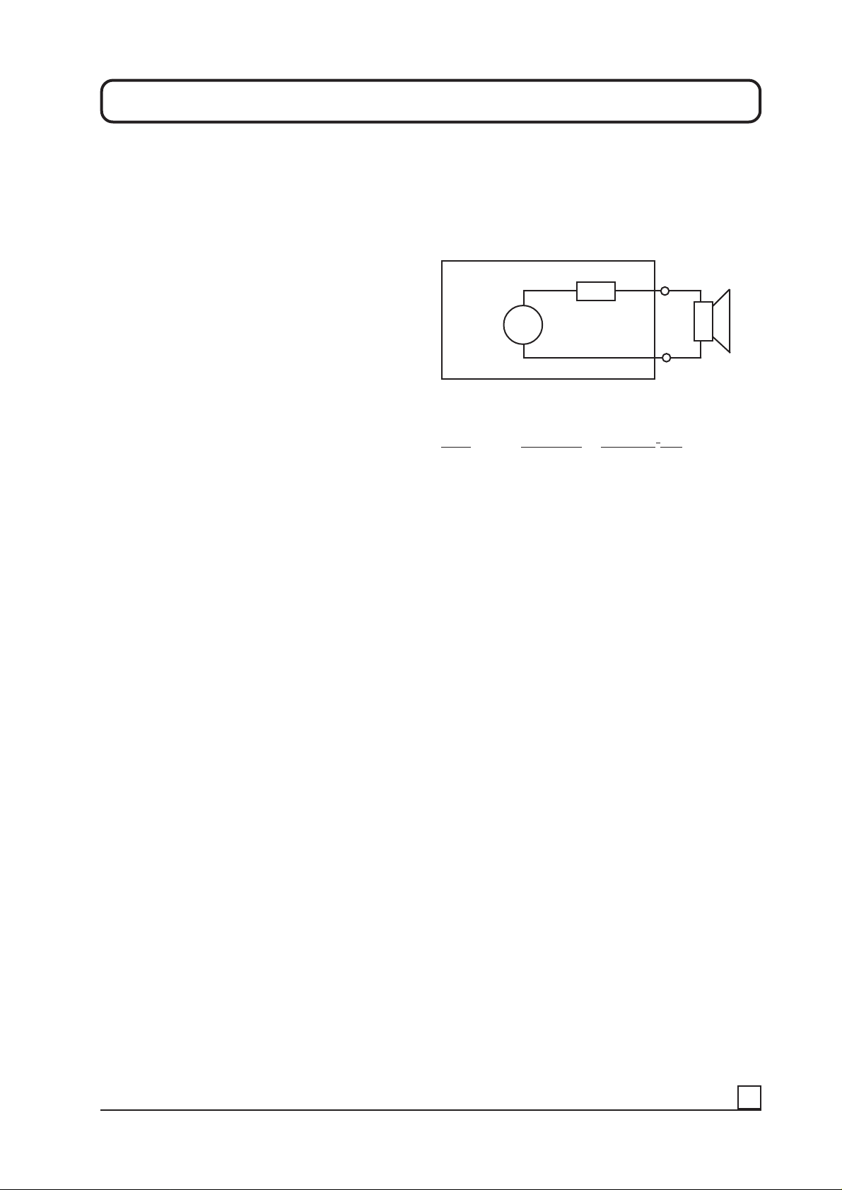
A modern car amplifier is always designed in such a way
that it tries to give a constant voltage output independent
of the speaker load impedance.
Let us study this drawing:
>
G
In this example the amplier has an output power of 50
Watts in a 4 ohm load. V
Load Output (V) Power (U2 / Z)
8 ohm 16 Volt 16 x 16 / 8= 32 Watt
4 ohm 14 Volt 14 x 14 / 4= 49 Watt
2 ohm 12 Volt 12 x 12 / 2= 72 Watt
1 ohm 8 V olt 8 x 8 / 1= 64 Watt
This amplifier is recommended by the producer not to be
loaded below 2 ohms, it is what we normally say, 2 ohm
stable. It can be loaded with a speaker impedance of 2
ohms in stereo mode without beeing damaged. If it gets
too hot there are hopefully some protection circuits that
shuts the amplifier down until it has cooled off. Amplifiers
that are used at high volumes for long periods might need
to have an extra cooling with one or more fans.
Z i
Z
Besides the use as an impedance-matching transformer
the DLS Z-match evens the impedance peak that occours
at the resonant frequency and in that way the impedance
load is improved for the amplifier.
CAUTION!
If an amplifier is loaded with a lower impedance than it is
designed for it can be damaged, especially if the load
lasts for a longer period.
DLS takes no responsability for damaged amplifiers or
speakers if they have been connected to a DLS Z-match.
DLS Z-match is mainly designed for increasing the
amplifier output by loading it with a low impedance load.
(not lower than the lowest load recommended by the
producer). Be aware that when the amplifier output
increases the damping factor gets lower. The damping
factor is the amplifiers ability to control the speaker cone
movement as precise as possible. This means that an
amplifier with a low damping factor will be worse when
the amplifier is loaded down and the output gets higher.
The higher output power is achieved on the cost of lower
damping factor.
On the other hand, when transforming up the speaker
impedances the damping factor will be increased
accordingly.
Maximum power handling capacity for the DLS Z-match
is 500 Watts.
We can see that the output power increases when the
speker load decreases, down to two ohms. At 1 ohm load
the output power gets less again, so it´s no meaning to
load the amplifier that low. The amplifier will probably be
damaged after some time, and the distortion will also
increase.
All amplifiers has an internal impedance, see the drawing
above where it is called Zi. As the amplifier is loaded with
lower and lower speaker impedances the loss of heat
increases in Zi. Maximum output is obtained when the
speaker impedance load is equal to the internal
impedance of the amplifier. In the example above the
internal impedance seems to bee around two ohms.
It is not obvious that all amplifiers can be loaded down to
it´s internal impedance. Many amplifiers have protection
circuits that shuts the amplifier off, and some amplifiers
will broke at low impedance loads.
Conclusion: An amplifier can not be loaded below the
limit set by the producer. High ambient temperatures, longtime playing at high volumes and speakers with a ”mean”
impedance curve demands a good external cooling and
here the DLS Z-match can be used only to improve the
impedance matching between amplifier and speakers.
1
Page 2
2. Speaker impedances:
Most speakers for car use has an impedance of 4 ohms.
The speakers can be connected in many different ways to
obtain the wanted impedance. They can be connected in
series, in parallel or other combinations.
Speakers with dual voice coils are normally connected
as if they were two speakers.
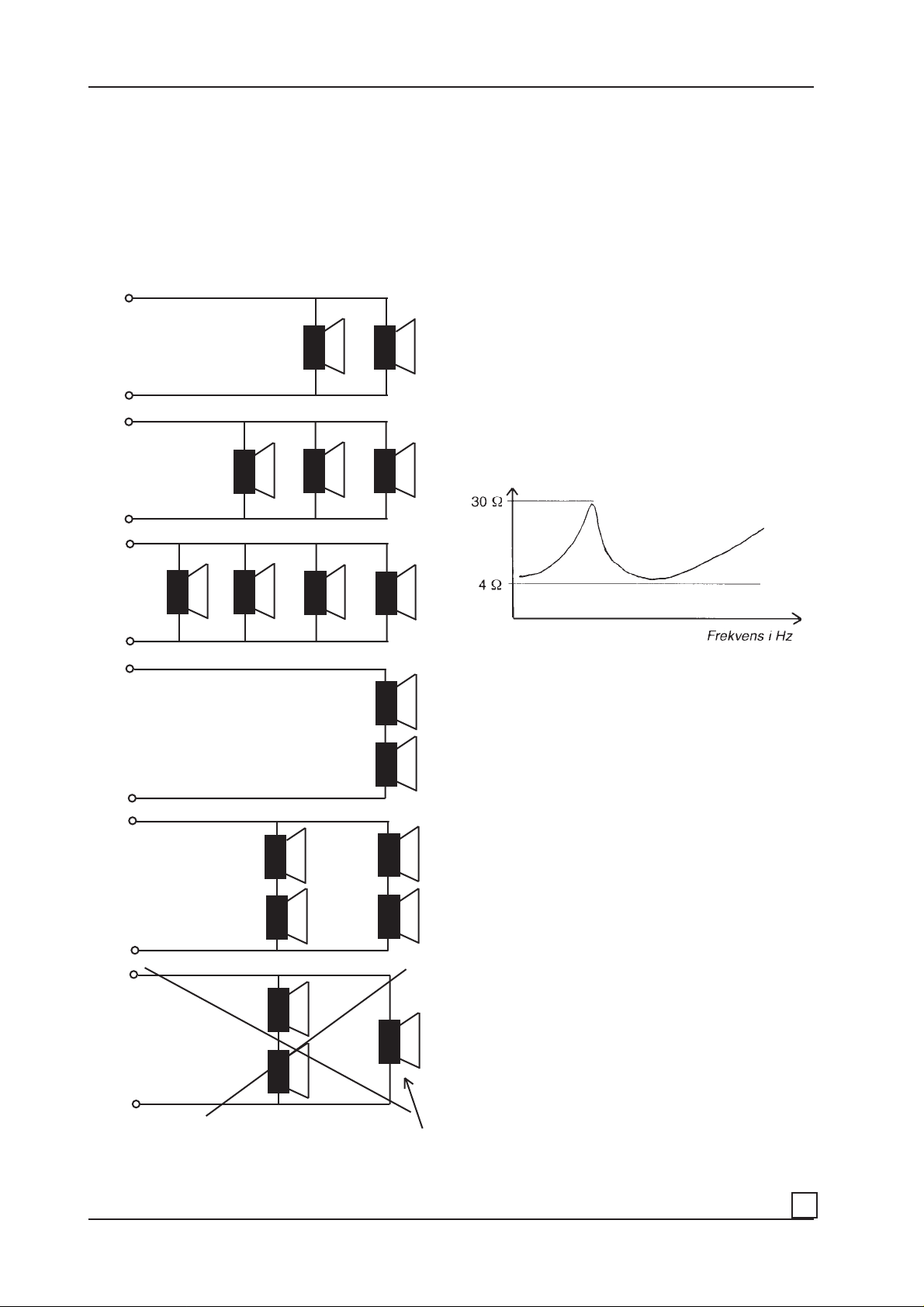
The examples below shows different ways to connect
speakers and the resulting impedance obtained when
using 4 ohm speaker elements.
2 ohm
1,33
ohm
When two speakers are connected in parallel the
impedance is halved.
When two speakers are connected in series the
impedance is doubled.
This is for identical speakers having the same impedance.
In the examples we see the speakers as resistors, a
component used for electronic devices which has a
resistance not varying with the frequency.
The resistance of a speaker can be measured with an
omh-meter. The so called DC resistance is normally 80 %
of the speaker impedance. A four ohm speaker has a DC
resistance of approximately 3,2 ohms.
The impedance is the resistance for alternating current
(AC).
All speakers has an impedance that varies with the
frequency with a peak at the resonant frequency (Fs).
The nominal impedance is the lowest impedance the
speaker has in the impedance curve, see the drawing
below.
1 ohm
8 ohm
4 ohm
2,67
ohm
At the resonant frequency the speaker has an impedance
of 15 - 30 ohms when the nominal impedance is 4 ohms.
The impedance curve is also influenced if it´s placed inside an enclosure, and also how this enclosure is designed.
Some types of vented boxes makes the impedance curve
more ”mean” as seen from the amplifier.
Some subwoofers has an impedance lower than the nominal 4 ohms and can be very ”mean” to the amplifier. It is
not quite sure that an amplifier loaded with 4 ohms are
happy with that if it handles 4 ohm load with only small
tolerances. The amplifier in our example should be able
to handle also ”mean” 4 ohm speakers.
Two ”mean” 4 ohm speakers in parallel offers a resulting
two ohm load, but still a ”mean” two ohm load.
The amplifier in our example should probably don´t like a
”mean” two ohm load.
With the DLS Z-match you can improve the impedance
curve and the amplifier will sense a nicer load.
In the example above a”mean” two ohm load can be transformed into a nicer four ohm load to the price of a little
lower output, but improved sound.
This example should never be used. The speaker to the
right plays with four times more power than the two
others.
But the normal use of the Z-match is to increase the power
output from the amplifier by loading it down.
2
Page 3
3. DLS Z-match:
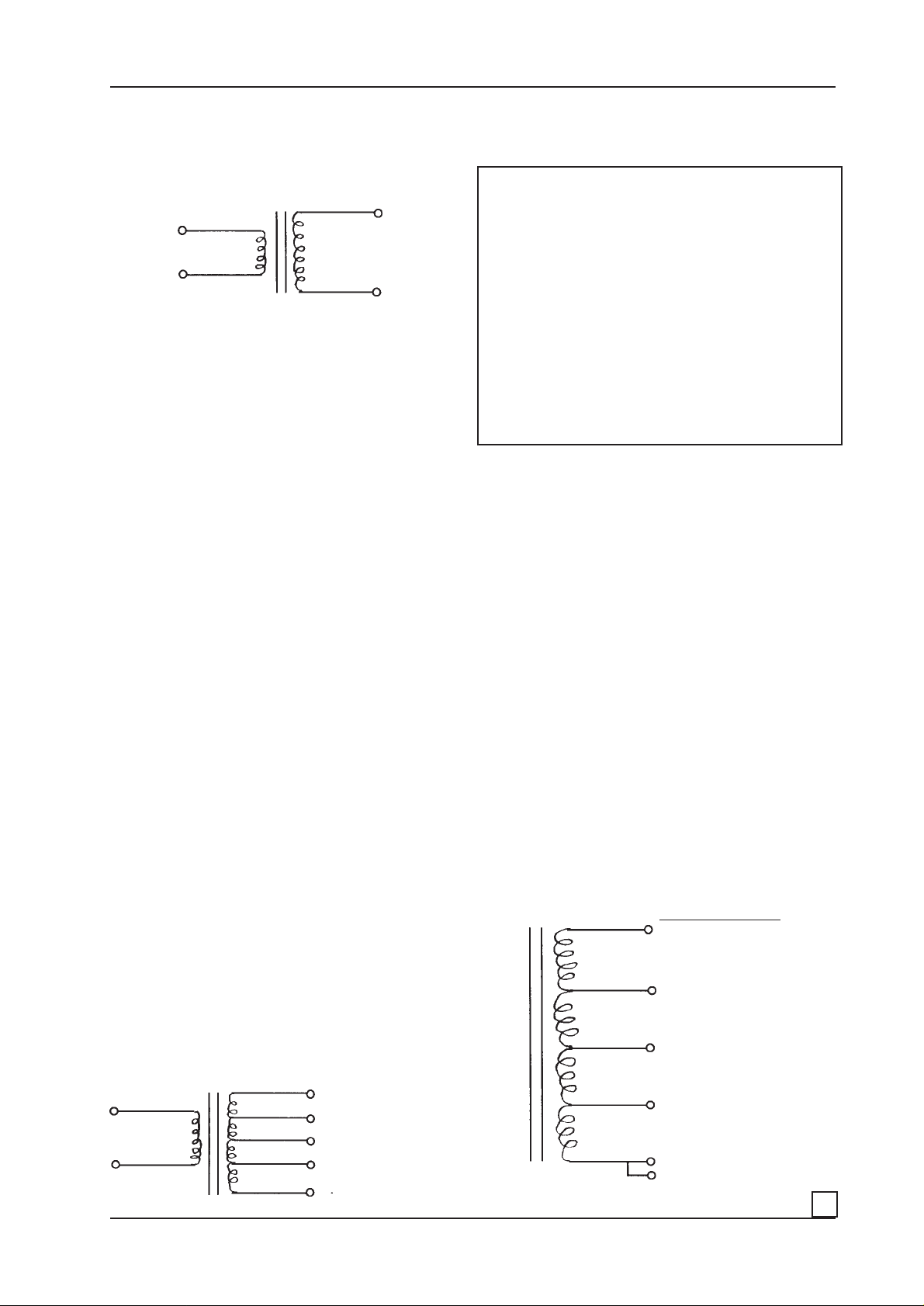
DLS Z-match can be described as a transformer with many
taps (terminals).
An ordinary transformer has a primary side and a
secondary side.
Primary 100 turns 200 turns secondary
10 volt 20 volt
The transformer above has a primary side of 100 turns of
heavy copper wire on an iron core, and a secondary side
of 200 turns of not so heavy copper wire on the same
core.
This transformer transforms a primary voltage of for
example 10 volts to a secondary voltage of 20 volts.
If you connect 10 volts to the secondary side you will have
5 volts out on the primary side.
If the transformer is designed to be used for audio
frequencies, and for impedances of one up to 10 ohms it
can be used to transform the impedance of a speaker to
become higher or lower.
If a 4 ohm speaker is connected to the primary side, the
one with 100 turns, an amplifier connected to the
secondary side will sense a speaker impedance of 16
ohms.
This caculated with this formula: Zs = Zp x ( n2 / n1 )
2
If you repeat the calculations you will find that:
A four ohm speaker connected to the primary side, and
an amplifier connected to the secondary side senses:
On tap 1: 4 ohms
On tap 2: 8 ohms , the impedance x 2
On tap 3: 16 ohms, the impedance x 4
On tap 4: 32 ohms, the impedance x 8
If you connect the speaker to the secondary side, and an
amplifier to the primary side it will sense: (when the speaker is connected to the following taps)
0 and tap 1: 4 ohms, divided by 1
0 and tap 2: 2 ohms, divided by 2
0 and tap 3: 1 ohm, divided by 4
0 and tap 4: 0,5 ohm, divided by 8
This is the principles behind the Z-match. But it differs on
some points.
The transformer described above is a transformer with
separate primary and secondary windings insulated from
each other.
DLS Z-match is an auto-connected transformer with a
single winding equivalent to the secondary winding above.
In this way the power handling capacity is increased and
it makes the transfor mer cheaper and not so heavy.
Zp is the impedance of the speaker connected to the
primary side, in this case 4 ohms. n2 / n1 is the ratio
between the number of turns on the secondary side (n2)
and the number of turns on the primary side (n1)
In this case the ratio is 200 turns / 100 turns = 2.
This is also the ratio between the secondary voltage and
the primary voltage, 20 volts / 10 volts = 2.
Put the figures into the formula and the result is
Zs = 4 x 2 x 2 = 16.
If we connect our speaker to the secondary side instead,
and calculate the impedance the amplifier sees when it´s
connected to the primary side.
Here the speaker impedance will be divided by four and
the amplifier sees a 1 ohm load. With this simple transformer I can increase a speaker impedance by four times,
or divide it by four.
If you add two taps to the secondary winding, one at 100
turns, one at 141 turns and add some more turns it can be
as below:
Primary side: Secondary side:
Tap 1 100 turns Tap 4 283 turns
for ex. 10 Volt gives 28 Volts
Tap 3 200 turns
4 x 8
3 x 4
2 x2
1 x 1
0
gives 20 Volts
Tap 2 141 turns
gives 14 Volts
Tap 1 100 turns
gives 10 Volts
The transformer losses will increase at frequencies over
10 kHz, especially when you use the x 8 terminal. This is
normally no problem since the Z-match is mostly used for
subwoofers.
When connecting speakers to a car amplifier it is very
important that no connections comes near and in contact
with the vehicle - ground. The same is for all connections
to the Z-match.
Transf ormer ratio:
4 ohm Volt
x 8 x 2,8
3
x4 x2
2
x2 x1,4
1
x1 x1
0
3
Page 4

3. Amplifiers in bridge mode
In chapter one we described the output impedance on an
amplifier. We presumed that the amplifier had two
channels and studied how it could be loaded down in
stereo mode, that is with speakers connected in stereo to
each channel.
Most car stereo amplifiers can also be used as mono
amplifiers. We call this mono bridge mode operation. The
amplifiers can be run in multimode operation or tri-mode.
Examples:
- My amplifier can handle 2 ohm loads in bridge mode.
- My two subs has 4 ohm impedance each.
If I connect a 4 ohm sub per channel I will have 100 Watts
per channel.
With a two ohm load per channel I will have 180 Watts per
channel.
This means a four ohm load in bridge mode.
All bass sound below 100 Hz are normally recorded in
mono. There is no need to have a subwoofer for each
channel. It is better to use the amplifier in mono connected
to a bass enclosure containing one or more subwoofers.
Most car amplifiers are stereo. They have two channels
connected two separate speakers, normally a front or rear
system. For bass reproduction we can use an identical or
maybee a more powerful amplifier. Sometimes a four
channel amplifier is to be prefered.
In bridge mode both amplifier channels are connected in
a way so that a mono subwoofer can be connected
between L+ and R- (see the amplifier manual for correct
information).
Actually both amplifiers are internally connected in series
causing the output voltage to double. At an unchanged
load (4 ohm) the power output is increased 4 times
compared with if the speaker was connected to only one
channel. The double voltage has caused a twice as high
current. The power P = U x I, the new power is
P=2U x 2I = 4 X U x I.
It means that an amplifier with 2 x 50 Watt output in stereo
can deliver up to 200 Watts to a 4 ohm speaker connected
in bridge mode.
It is very important to understand that each channel of the
stereo amplifier see half the actual speaker impedance.
If you load an amplifier in bridge mode with 4 ohms each
amplifier part senses a 2 ohm load. If the amplifier can´t
handle 2 ohm loads (not 2 ohm stable) the amplifier s
protection circuits will shut off the amplifier, or it will be
damaged.
If two 4 ohm subwoofers are connected in parallel,
resulting in a 2 ohm speaker impedance, the amplifier
senses a 1 ohm load per channel. If this load also is
”mean” the amplifier shuts off or burns.
In this situation you must use a DLS Z-match to increase
the impedance sensed by the amplifier.
Here you simply connect the 2 ohm load to terminal 0 and
2, and the amplifier is connected to terminal 0 and 3.
The speakers can also be connected in series to 8 ohm
and connected to terminal 0 and 4. The amplifier is
connected to terminal 0 and 3 as before.
I can choose between:
1. Connecting the subs in parallel to two ohms..
Connect the subs between terminal 0 and 2.
Connect the amplifier between terminal 0 and 4
Now you get 2 x 180 Watts = 360 Watt mono out
from the amplifier. see page 6, example 3
2. Connecting the subs in series to eight ohms.
Connect the subs between terminal 0 and 4.
Connect the amplifier between terminal 0 and 3.
Now you get 2 x 180 Watts = 360 Watt mono out
from the amplifier. see page 6, example 5
Check carefully that nor the amplifier nor the Z-match gets
too warm. If the sound quality becomes bad, choose another load (higher).
Another example:
With the same amplifier as above I want to use a bass box
enclosure with three 4 ohm subs.
You can connect all three in parallel resulting in 1,33 ohm
impedance.
Or in series to 4 x 3 = 12 ohm.
In the first case we need to multiply the load with a factor
3, or at least 2,40.
There are the following alternatives:
2,40, that is 2,40 x 1,33 = 3,2 ohm
2,85, that is 2,85 x 1,33 = 3,8 ohm
3,35, that is 3,35 x 1,33 = 4,45 ohm
see page 6, example 2.
When connecting the speakers in series I need to multiply
the load with x 0,33 giving the following alternatives:
x 0,25 , that is 0,25 x 12 = 3,0 ohm
x 0,30 , that is 0,30 x 12 = 3,60 ohm
x 0,35 , that is 0,35 x 12 = 4,20 ohm
x 0,42 , that is 0,42 x 12 = 5,04 ohm
see page 6, example 6
As you can see there are solutions to most adaption
problems. On the following pages there are examples on
the most common ways to connect subwoofers to
amplifiers.
Turbo-button
Among competitors in dB dragracing (SPL contests) it is
popular to increase the power by loading down the
amplifier for just a few seconds during the measure.
If you want to do this you must find the limit for what the
amplifier and speaker can handle during this short period
of time.
4
Page 5

On the following pages we present the most common
ways of connecting the Z-match. If you are familiar with
the technique of transforming we are sure that you can
find more ways of connecting the Z-match.
4. With 4 ohm speaker load
Connections with amplifiers that can
handle 2 ohm load in bridge mode, or 1
ohm in stereo mode. (1-ohm stable)
In all examples below 4 ohm speakers are used.
1. With 1 ohm speaker load:
0 0 1 2 3 4
Amplifier connected between 0 - 2, sees a 2 ohm load
Speakers connected between 0 - 1, (1 ohm load)
2. With 1,33 ohm speaker load:
0 0 1 2 3 4
Amplifier connected between 0 - 2, sees a 2 ohm load
Speakers connected between 0 - 3, (4 ohm load)
5. With 8 ohm speaker load
0 0 1 2 3 4
_
+
+
_
0 0 1 2 3 4
Amplifier connected between 1 - 4, sees a 2.2 ohm load
Speakers connected between 0 - 2, (1,33 ohm load)
3. With 2 ohm speaker load:
0 0 1 2 3 4
Amplifier connected between 1 - 3, sees a 2 ohm load
Speakers connected between 0 - 1, (2 ohm load)
Used only as an impedance corrector. The amplifier
load becomes ”nicer”.
Amplifier connected between 0 - 2, sees a 2 ohm load
Speakers connected between 0 - 4, (8 ohm load)
6. With 12 ohm speaker load
0 0 1 2 3 4
+
_
Amplifier connected between 2 - 3, sees a 2 ohm load
Speakers connected between 0 - 2, (12 ohm load)
Summary:
Connections with amplifiers that can handle 1 ohm
load in bridge mode, or 2 ohm in stereo mode.
Speaker Connect Connect Amplifier
load amplifier to speakers see the load
to terminal: to terminal: as:
1 ohm 0 - 2 0 - 1 2 ohm
1,33 ohm 1 - 4 0 - 2 2,22 ohm
2 ohm 1 - 3 0 - 1 2 ohm
4 ohm 0 - 2 0 - 3 2 ohm
8 ohm 0 - 2 0 - 4 2 ohm
12 ohm 2 - 3 0 - 2 2 ohm
_
+
+
_
5
Page 6

Connections with amplifiers that can
handle 4 ohm load in bridge mode, or 2
ohm in stereo mode.
(2-ohm stable)
This type of amplifiers is the most common. They are
what we say ”2 ohm stable”. They can be loaded with 2
ohm in stereo and 4 ohm in mono bridge mode.
In all examples below 4 ohm speakers are used.
1. WIth 1 ohm speaker load:
4. With 4 ohm speaker load
0 0 1 2 3 4
Amplifier connected between 1 - 3, sees a 4 ohm load
Speakers connected between 0 - 1, (4 ohm load)
Used only as an impedance corrector. The amplifier
load becomes ”nicer”.
0 0 1 2 3 4
Amplifier connected between 0 - 3, sees a 4 ohm load
Speakers connected between 0 - 1, (1 ohm load)
2. With 1,33 ohm speaker load
0 0 1 2 3 4
Amplifier connected between 1 - 4, sees a 4,45 ohm load
Speakers connected between 1 - 3, (1,33 ohm load)
3. With 2 ohm speaker load
5. With 8 ohm speaker load
0 0 1 2 3 4
_
+
Amplifier connected between 0 - 3, sees a 4 ohm load
Speakers connected between 0 - 4, (8 ohm load)
6. With 12 ohm speaker load
0 0 1 2 3 4
+
_
_
+
+
_
+
_
0 0 1 2 3 4
Amplifier connected between 0 - 3, sees a 4 ohm load
Speakers connected between 0 - 2, (2 ohm load)
Amplifier connected between 1 - 4, sees a 5 ohm load
Speakers connected between 0 - 4, (12 ohm load)
Summary:
Connections with amplifiers that can handle 4 ohm
load in bridge mode, or 2 ohm in stereo mode.
Speaker Connect Connect Amplifier
load amplifier speakers see the load
to terminal: to terminal: as:
1 ohm 0 - 3 0 - 1 4 ohm
1,33 ohm 1 - 4 1 - 3 4,46 ohm
2 ohm 0 - 3 0 - 2 4 ohm
4 ohm 1 - 3 0 - 1 4 ohm
8 ohm 0 - 3 0 - 4 4 ohm
12 ohm 1 - 4 0 - 4 5 ohm
6
Page 7

Connections with amplifiers that can
handle 8 ohm load in bridge mode, or 4
ohm in stereo mode.
(4-ohm stable)
This group of amplifiers are no longer common. Only
cheap or older amps can only handle a minimum of 4
ohm load in stereo mode.
In all examples below 4 ohm speakers are used.
1. With 1 ohm speaker load:
4. With 4 ohm speaker load
0 0 1 2 3 4
Amplifier connected between 0 - 4, sees an 8 ohm load
Speaker connected between 0 - 3, (4 ohm load)
0 0 1 2 3 4
Amplifier connected between 0 - 4, sees an 8 ohm load
Speakers connected between 0 - 1, (1 ohm load)
2. With 1,33 ohm speaker load
0 0 1 2 3 4
Amplifier connected between 1 - 3, sees a 7,85 ohm load
Speakers connected between 1 - 2, (1,33 ohm load)
3. With 2 ohm speaker load
5. With 8 ohm speaker load
0 0 1 2 3 4
_
+
Amplifier connected between 1 - 3, sees an 8 ohm load
Speakers connected between 0 - 1, (8 ohm load)
Used only as an impedance corrector. The amplifier
load becomes ”nicer”.
6. With 12 ohm speaker load
0 0 1 2 3 4
+
_
_
+
+
_
+
_
0 0 1 2 3 4
Amplifier connected between 0 - 4, ses an 8 ohm load
Speakers connected between 0 - 2, (2 ohm load)
Amplifier connected between 0 - 2, sees a 7,2 ohm load
Speakers connected between 1 - 4, (12 ohm load)
Summary:
Connections with amplifiers that can handle 8 ohm
load in bridge mode, or 4 ohm in stereo mode.
Speaker Connect Connect Amplifier
load amplifier speakers see the load
to terminal: to terminal: as:
1 ohm 0 - 4 0 - 1 8 ohm
1,33 ohm 1 - 3 1 - 2 8 ohm
2 ohm 0 - 4 0 - 2 8 ohm
4 ohm 0 - 4 0 - 3 8 ohm
8 ohm 1 - 3 0 - 1 8 ohm
12 ohm 0 - 2 1 - 4 7 ohm
7
Page 8

Other alternatives for connecting Z-match.
This is a table with more alternatives of impedance ratios than the ones on previous pages.
Suitable for you who looks for alternative connections.
Impedance Speaker Amplifier Connect Connect
ratio load see a load of: amplifier speaker load
x (ohm) (ohm) to terminal: to terminal:
0,125 8 1 0 - 1 0 - 4
16 2 0 - 1 0 - 4
0,17 8 1,35 1 - 2 1 - 3
12 2 1 - 2 1 - 3
16 2,7 1 - 2 1 - 3
0,18 8 1,4 2 - 3 0 - 2
0,20 8 1,6 3 - 4 1 - 4
0,25 4 1 0 - 1 0 - 3
8 2 0 - 2 0 - 4
0,30 8 2,4 0 - 1 1 - 4
0,35 4 1,4 2 - 3 1 - 3
8 2,8 2 - 3 1 - 3
0,42 4 1,68 1 - 4 0 - 4
8 3,36 1 - 4 0 - 4
12 5,04 1 - 4 0 - 4
0,48 4 1,92 1 - 2 2 - 3
8 3,84 1 - 2 2 - 3
0,50 4 2 0 - 2 0 - 3
8 4 0 - 3 0 - 4
0,60 4 2,4 0 - 2 1 - 4
8 4,8 0 - 2 1 - 4
12 7,2 0 - 2 1 - 4
0,69 4 2,75 3 - 4 0 - 1
0,85 4 3,33 1 - 4 0 - 3
1 4 4 1 - 3 0 - 1
1,20 2 2,4 0 - 3 1 - 4
4 4,80 0 - 3 1 - 4
1,45 1,33 1,93 1- 3 3 - 4
2 2,90 1 - 3 3 - 4
1,67 1,33 2,22 1 - 4 0 - 2
2 3,33 1 - 4 0 - 2
2 1 2 0 - 2 0 - 1
2 4 0 - 3 0 - 2
4 8 0 - 4 0 - 3
2,4 1 2,40 0 - 4 1 - 4
2 4,80 0 - 4 1 - 4
2,85 1 2,85 0 - 1 2 - 3
3,35 0,5 1,65 1 - 4 0 - 1
1 3,35 1 - 4 0 - 1
1,33 4,46 1 - 4 0 - 1
4 0,5 2 0 - 3 0 - 1
1 4 0 - 3 0 - 1
4,85 0,5 2,53 1 - 4 3 - 4
1 4,85 1 - 4 3 - 4
5,9* 0,5 2,95 0 - 1 1 - 2
1 5,90 0 - 1 1 - 2
1,33 7,85 0 - 1 1 - 2
8 0,5 4 0 - 4 0 - 1
1 8 0 - 4 0 - 1
11,.* 0 , 5 6 0 - 2 1 - 2
1 12 0 - 2 1 - 2
* test carefully, only recommended for short per iod testing
DLS Svenska AB
P.O. Box 13029
Artillerigatan 25
SE-402 51 Göteborg
Sweden
Phone: +46 31 840060
Fax: +46 31 844021
E-mail: info@dls.se
www.dls.se
8
 Loading...