

Page 1
DLP® Discovery
This guide describes how to assemble the components of the DLP® DiscoveryTM 4100 series of
development kits. Adhere to safety precautions when handling systems. The key components include the
D4100 Controller Board and DMD Assembly. Review safety precautions prior to geing started.
TM
D4100 Development Kits Assembly Guide
Items Needed:
4 D4100 Controller Board
4 DMD Assembly
4 DMD Board
4 DMD Hardware
4 Flex Cable(s) (XGA - 1 / 1080p - 2)
4 Phillips head screwdriver
4 Anti-static pad
4 Anti-static strap
Section 1: Congurations
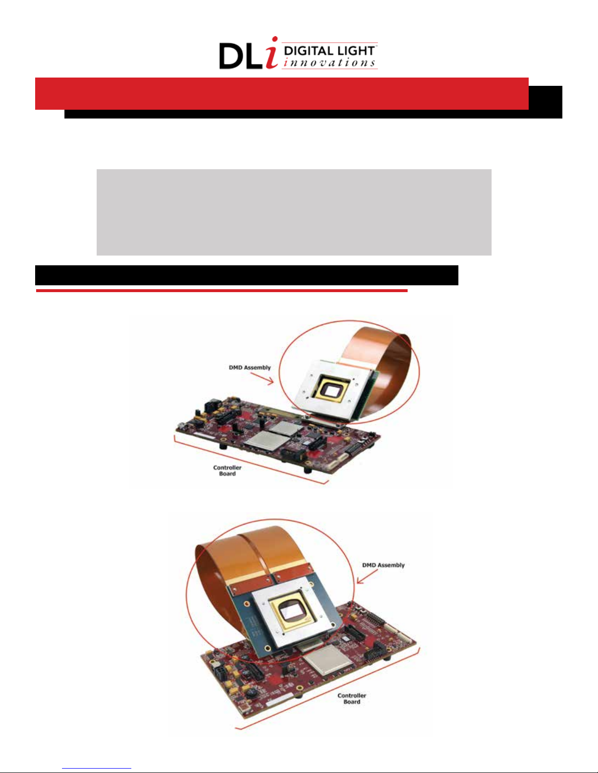
Figure 1-1. DLP Discovery 4100 .7” XGA Development Kit
Figure 1-2. DLP Discovery 4100 .95” 1080p Development Kit
1
Page 2
Section 2: Components
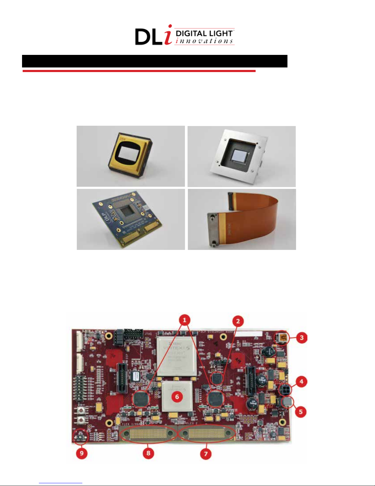
1. DMD Assembly Components
1. DMD
2. DMD Mounting Hardware
3. DMD Board
4. Flex Cable(s) (XGA - 1 / 1080p - 2)
Figure 2-1. DMD Assembly Components
1. 2.
3.
2. D4100 Controller Board Components:
1. DLPA200 Driver(s) (XGA - 1 / 1080p - 2)
2. DLPR410 PROM
3. USB Mini-B Connector
4. Power Connector
5. Power Socket
Figure 2-2. D4100 Controller Board Components (Top View)
4.
6. DLPC410 Digital Controller
7. DMD Flex Cable Connector 2
8. DMD Flex Cable Connector 1 (1080p – Flex 1 & 2)
9. Power Switch
(XGA – Flex 1)
2
Page 3
Section 3: Hardware Setup
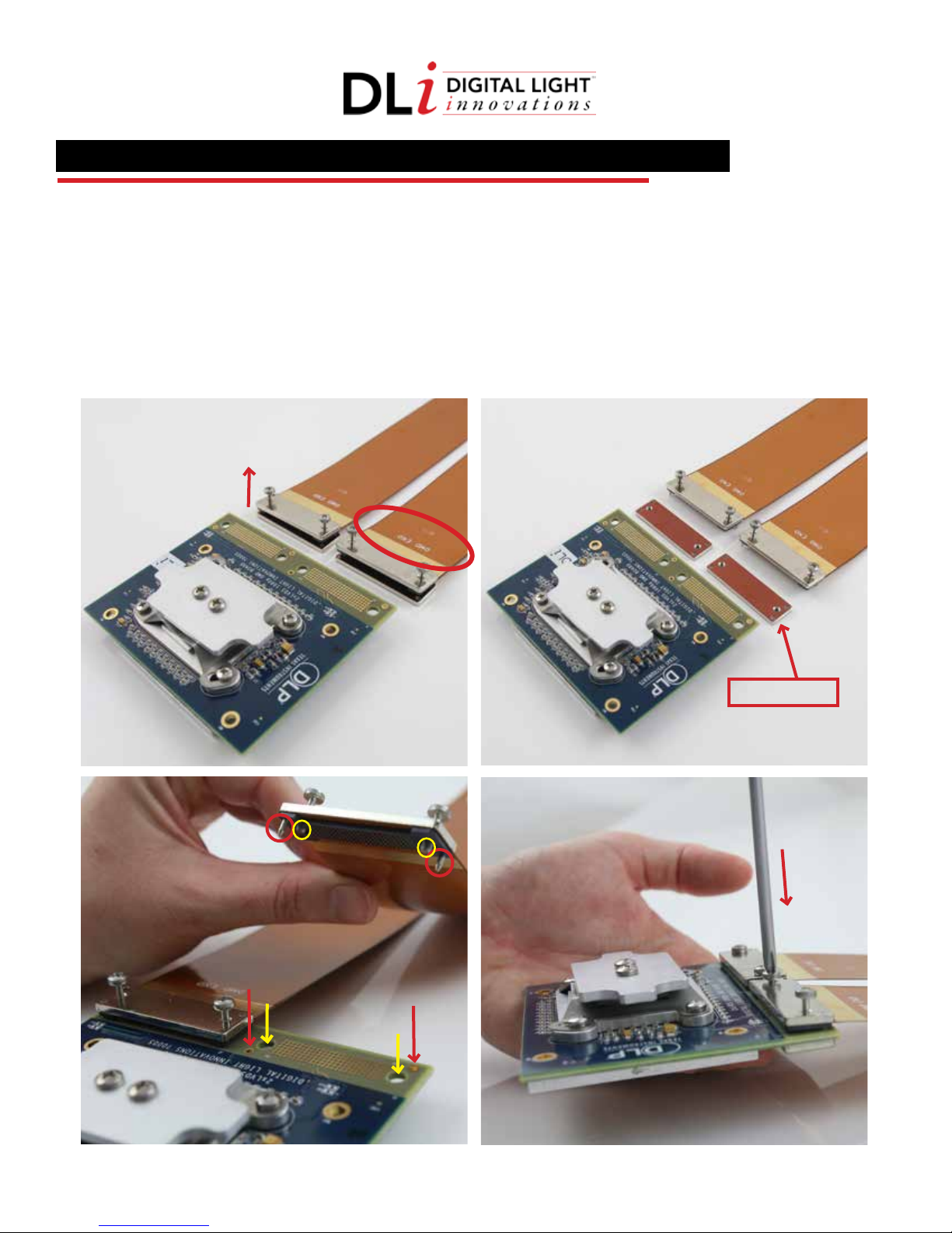
1. Connecting Flex Cable(s) to DMD Board
4 Locate end of the flex cable labeled DMD END
4 Position DMD Assembly face down
4 Unscrew flex cable screws from backer plate
4 Position backer plate under DMD board
4 Align flex cable screws and pins to corresponding holes on DMD board
4 Screw flex cable(s) in place making sure not to overtighten
Figure 3-1. Connecting Flex Cable(s) to DMD Board
a.
c.
Backer Plate
b.
d.
3
Page 4
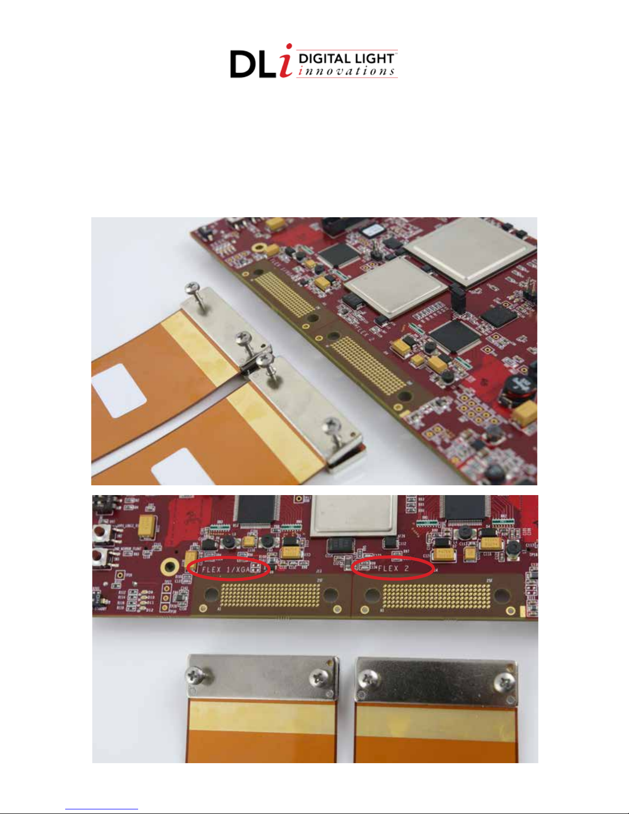
2. Connecting Flex Cable(s) to 4100 Controller Board
4 Locate end of the flex cable NOT labeled DMD END
4 Position controller board to face up
4 Unscrew flex cable screws from backer plate
4 Position backer plate under controller board
4 Align screws and pins on the flex cable to corresponding holes on controller board
4 Screw flex cable(s) in place making sure not to overtighten
Figure 3-2. Connecting Flex Cable(s) to DMD Board
a.
b.
4
Page 5

PRECAUTIONS
Before handling, assembling or operating your development kit, please read the following
precautions thoroughly. DLP® systems contain electrostatic discharge (ESD) sensitive components.
Handle with care to prevent permanent damage. The system electronics are exposed and sensitive
to electrostatic discharge, rough handling and contact with external elements. Utilize ESD
procedures and equipment for proper grounding when handling kits to avoid electrostatic
discharge damage.
ESD precautions include but are not limited to the following list:
4 Discharge static electricity from your body before handling system
4 Turn o the system and any attached peripherals
4 Disconnect the system and any attached peripherals from AC power
4 Wear an anti-static wrist strap that is properly grounded
4 Work in clean, static-safe work areas
4 Handle components on static protective work surfaces (i.e. anti-static discharge mats or bags)
4 Avoid touching pins and circuit boards
4 Store components in anti-static bags until ready to use
4 Transport system in anti-static packaging
CAUTION! Contains parts and assemblies susceptible to damage by Electrostatic Discharge (ESD).
CAUTION! To minimize the risk of re or equipment damage, make sure that air is allowed to
circulate freely around the development kit when operating. Avoid touching components during
operation.
Copyright ©2018 Digital Light Innovations. All Rights Reserved.
5
DLi 1809A
 Loading...