

Page 1
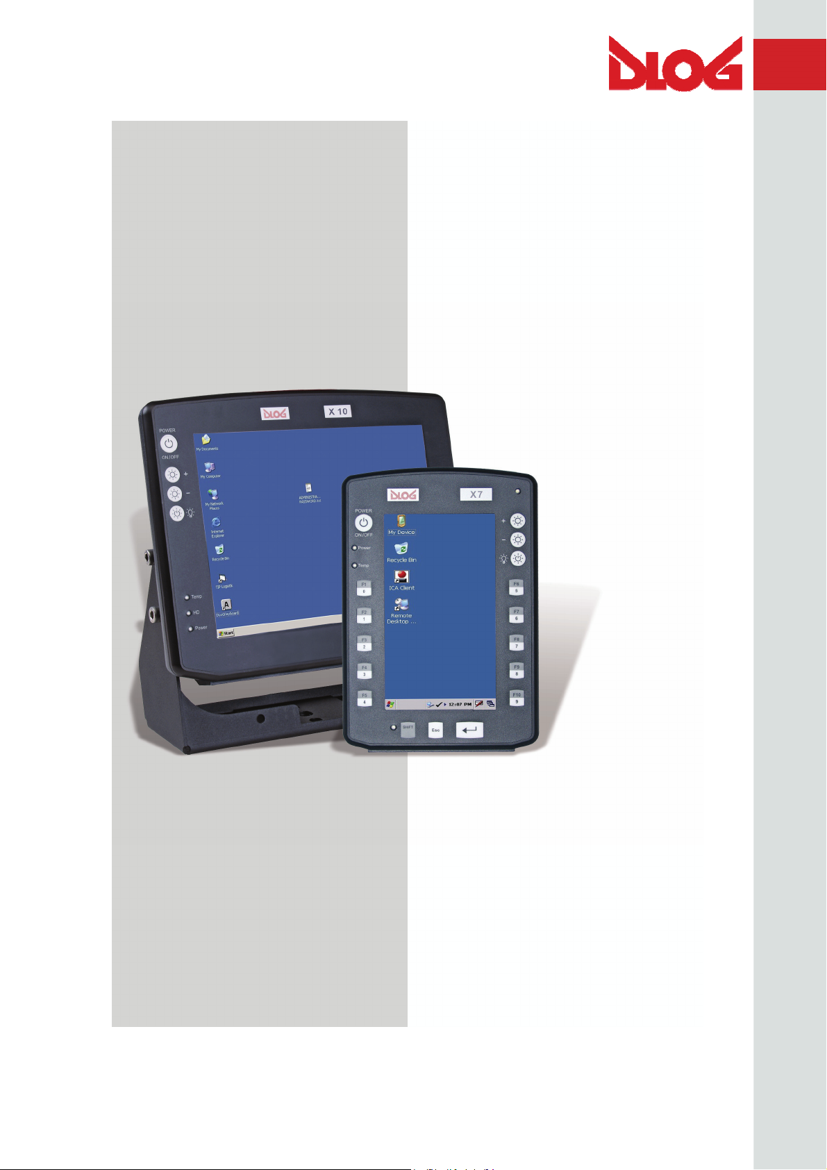
DLoG X 7
DLoG X 10
DLoG X 12
Manual
3.10
Page 2

This manual contains a detailed description of the product and we have made every effort to make it as
accurate as possible. However, this is not a guarantee of the features or the functionality of the product.
We reserve the right to modify the contents of this document at any time and without prior notice.
Because we at DLoG are constantly striving to improve this product, we cannot guarantee that previous
or subsequent releases of the product will correspond in every respect with the product description
given in this manual.
DLoG GmbH assumes no liability for technical inaccuracies, typographic errors or faults in this
documentation. DLoG GmbH also assumes no liability for damages caused directly or indirectly by the
delivery, performance or usage of this material.
The software and hardware designations used in this documentation are in most cases also registered
trademarks and are thus subject to law.
Windows® is a registered trademark of Microsoft Corporation in the United States (US) and other
countries.
This documentation is protected by copyright. Duplication, in whole or in part, is not permitted without
prior written approval of DLoG GmbH!
Title of documentation: Manual DLoG X 7, DLoG X 10, DLoG X 12
Documentation completed on: 22nd of May 2007
Version: 3.10
Product number: 885233E.50
© Copyright 2005-2007
DLoG GmbH
Werner-von-Siemens-Straße 13
D-82140 Olching, Germany
All rights reserved
Technical customer support
If you experience technical difficulties, please
consult your distributor or contact the technical
services department at DLoG’s headquarters:
(+49) 8142 / 28 60 – 0
www.dlog.com
Page 3
Page 4

Table of contents
1. About this manual..................................................................................1
1.1. Device version described ..........................................................................................1
1.2. For qualified personnel.............................................................................................. 1
1.3. Design method ..........................................................................................................2
1.3.1. Warnings and notices........................................................................................2
1.3.2. Additional design elements ...............................................................................2
2. Important safety notices........................................................................4
2.1. Initial operation of the device..................................................................................... 4
2.2. Power supply / External peripheral devices ..............................................................6
2.3. Repairs only through DLoG....................................................................................... 7
2.4. Opening and closing the device ................................................................................ 7
2.5. Exchanging and extending modules .......................................................................10
2.6. CE Marking.............................................................................................................. 12
2.7. RTTE Directive 1999/5/EC ......................................................................................12
2.7.1. Special regulations in France.......................................................................... 12
2.8. FCC user information ..............................................................................................13
2.8.1. Interference declaration of the Federal Communications Commission .......... 13
2.8.2. Transmission of radio frequencies .................................................................. 14
3. Device description ...............................................................................15
3.1. General.................................................................................................................... 15
3.2. Intended usage........................................................................................................16
3.3. Models ..................................................................................................................... 17
3.4. Abbreviations used for devices and accessories .................................................... 17
3.5. Device description and type identification ............................................................... 18
3.5.1. Device type plate.............................................................................................18
3.6. Technical specifications........................................................................................... 19
3.6.1. System equipment........................................................................................... 19
Page 5

3.6.2. Power supply / Power packs ...........................................................................23
3.6.3. AC power packs...............................................................................................25
3.6.4. Maximal power available for peripheral devices..............................................26
3.6.5. Test marks .......................................................................................................27
3.6.6. Dimensions ......................................................................................................28
3.6.7. VESA drill holes...............................................................................................37
4. Unpacking the device...........................................................................40
4.1. Scope of delivery .....................................................................................................40
4.2. Packaging ................................................................................................................40
4.3. Returning your device..............................................................................................40
5. Initial operation.....................................................................................41
5.1. Cooling through the supply of fresh air....................................................................41
5.2. External connectors DLoG X 7 ...............................................................................42
5.2.1. Standard connectors........................................................................................42
5.2.2. Optional connectors.........................................................................................42
5.2.3. Power pack models .........................................................................................44
5.3. External connectors DLoG X 10 and DLoG X 12 ....................................................46
5.3.1. Standard connectors........................................................................................46
5.3.2. Optional connectors.........................................................................................46
5.3.3. Power pack models .........................................................................................47
5.4. Connecting/Disconnecting external devices............................................................49
5.4.1. USB connection...............................................................................................49
5.4.2. COM connection..............................................................................................49
5.5. Powering up the device ...........................................................................................51
5.6. Removing the protective film from the front.............................................................51
5.7. Protecting the TFT display from the memory effect.................................................52
5.8. Installing Application Software.................................................................................52
5.9. Important Software Settings ....................................................................................53
5.9.1. Wireless network .............................................................................................53
5.9.2. Touch screen calibration .................................................................................53
5.10. After extended non-use .......................................................................................54
Page 6

6. Accessories..........................................................................................55
6.1. Keyboard ................................................................................................................. 56
6.1.1. SMALL keyboard.............................................................................................56
6.1.2. 24-key keypad ................................................................................................. 57
6.2. Mouse...................................................................................................................... 58
6.3. USB Stick ................................................................................................................58
6.4. Scanners ................................................................................................................. 58
6.5. WLAN cards (PC cards) .......................................................................................... 58
6.6. CompactFlash .........................................................................................................58
6.7. Adapter cables......................................................................................................... 58
7. Mounting...............................................................................................59
7.1. Options for mounting the device.............................................................................. 59
7.2. Observe and retain the mounting instructions......................................................... 59
7.3. Mechanical dynamic loading ................................................................................... 60
7.4. Power supply ........................................................................................................... 60
7.4.1. DC power packs ..............................................................................................60
7.4.2. AC power packs .............................................................................................. 61
7.4.3. Installing connecting cables ............................................................................61
7.5. Vehicle applications (such as forklifts) ....................................................................62
7.5.1. DC terminals.................................................................................................... 63
7.6. Cable cover (Splash guard)..................................................................................... 64
7.6.1. Protection class IP65....................................................................................... 64
7.6.2. Protection class IP54....................................................................................... 64
8. Operation..............................................................................................65
8.1. Touch screen operation........................................................................................... 65
8.1.1. Dirty touch screen surface............................................................................... 65
8.2. Operating controls DLoG X 7 ..................................................................................66
8.2.1. Horizontal/vertical versions .............................................................................66
8.2.2. Standard configuration (4 keys) ...................................................................... 66
8.2.3. Extended configuration (17 keys).................................................................... 67
8.2.4. Brightness control............................................................................................ 67
Page 7

8.2.5. Front controls (standard) .................................................................................68
8.2.6. Front controls (extended) ................................................................................69
8.3. Operating controls DLoG X 10 and DLoG X 12.......................................................70
8.3.1. Front controls (standard) .................................................................................71
8.3.2. Front controls (extended) ................................................................................72
8.4. LED / Operating states ............................................................................................73
8.4.1. DLoG X 7 .........................................................................................................73
8.4.2. DLoG X 10 and DLoG X 12 .............................................................................73
9. Boot loader............................................................................................74
10. Operating system.............................................................................76
11. Software applications.......................................................................77
11.1. Settings with PD.EXE ..........................................................................................77
11.1.1. Configuring backlight, automatic switch off and more.................................77
11.1.2. PD.EXE dialogs horizontally or vertically ....................................................77
11.1.3. Save PD.EXE settings.................................................................................77
11.1.4. Launch PD.EXE...........................................................................................77
11.1.5. Menu bar......................................................................................................79
11.1.6. Options menu ..............................................................................................80
11.1.7. Advanced menu...........................................................................................88
11.1.8. Info menu.....................................................................................................91
12. Serial ports........................................................................................92
12.1. COM1 Options .....................................................................................................92
12.2. COM2 Options .....................................................................................................93
12.2.1. RS-4xx operation.........................................................................................93
12.3. Cable lengths and ground loops..........................................................................94
13. Audio (Option)...................................................................................95
13.1. Line In – Line Out ................................................................................................96
13.2. Mic In – Line Out..................................................................................................96
13.2.1. Circuit Diagram and Limitations...................................................................96
Page 8

14. Touch Screen (Option).....................................................................98
14.1. Mouse and keyboard compatibility...................................................................... 98
14.2. Functional description .........................................................................................98
14.3. Operation.............................................................................................................98
14.4. Drivers ................................................................................................................. 98
14.5. Calibration (Windows CE) ................................................................................... 99
14.6. Resistance.........................................................................................................100
14.6.1. Mechanical resistance............................................................................... 100
14.6.2. Chemical resistance.................................................................................. 100
15. Internal devices..............................................................................101
15.1. PCMCIA / PC cards (Option)............................................................................. 101
15.2. Heating (Option) ................................................................................................ 101
15.3. Automatic switch off (Option) ............................................................................102
15.3.1. Configuration with PD.EXE ....................................................................... 102
15.3.2. Overview of configuration settings ............................................................ 103
16. Maintenance....................................................................................104
16.1. Cleaning the housing......................................................................................... 104
16.2. Cleaning the touch screen................................................................................. 104
16.3. Cleaning the cooling fins ................................................................................... 104
17. Common mistakes in usage..........................................................105
17.1. Power supply..................................................................................................... 105
17.2. Powering up/powering down ............................................................................. 105
17.3. Cable cover .......................................................................................................105
17.4. Mounting............................................................................................................106
17.5. Mobile application on vehicles........................................................................... 106
17.6. Using the touch screen...................................................................................... 107
17.7. Cleaning the device........................................................................................... 108
17.8. Use/storage in extreme temperatures...............................................................108
Page 9

18. Disposal...........................................................................................109
19. Appendix A: Terminal assignment (Pins).....................................110
19.1. External connectors ...........................................................................................110
19.1.1. Power.........................................................................................................110
19.1.2. Signal.........................................................................................................112
19.2. Internal connectors mainboard MDA2.10 05.2006............................................118
19.2.1. Audio interface...........................................................................................125
20. Appendix B: Jumpers.....................................................................127
20.1. Warning..............................................................................................................127
20.2. Standard jumper settings...................................................................................127
20.3. Jumper layout view for mainboard MDA2.10 05.2006 ......................................128
20.3.1. COM1 Configuration..................................................................................129
21. Appendix C: Mechanical dynamic loading...................................130
21.1. Introduction ........................................................................................................130
21.2. Using the device without vibration insulation.....................................................132
21.3. Application with passive vibration insulation......................................................133
21.4. Dimensioning example DLoG X 10 ...................................................................134
21.4.1. Approximate solution for the selection of elastomer springs.....................135
21.4.2. Approximate solution for determining insulating effects............................138
21.5. Determining natural frequencies........................................................................140
22. Appandix D: Tools..........................................................................141
22.1. Warnings............................................................................................................141
22.2. Tool kit ...............................................................................................................142
22.2.1. Closing the device .....................................................................................142
22.3. Mounting bracket tool kit....................................................................................143
23. Return packing slip........................................................................144
Index............................................................................................................145
Page 10

List of figures
Figure 2.1: CE Marking.....................................................................................................12
Figure 3.1: DLoG X 7, vertical display..............................................................................15
Figure 3.2: DLoG X 10 and DLoG X 12............................................................................16
Figure 3.3: Example of a device type plate ...................................................................... 19
Figure 3.4: Dimensions DLoG X 7 front view ................................................................... 28
Figure 3.5: Dimensions DLoG X 7 side view....................................................................29
Figure 3.6: Dimensions DLoG X 7 top view .....................................................................30
Figure 3.7: Dimensions DLoG X 10 front view ................................................................. 31
Figure 3.8: Dimensions DLoG X 10 side view..................................................................32
Figure 3.9: Dimensions DLoG X 10 top view ...................................................................33
Figure 3.10: Dimensions DLoG X 12 front view ...............................................................34
Figure 3.11: Dimensions DLoG X 12 side view................................................................35
Figure 3.12: Dimensions DLoG X 12 top view .................................................................36
Figure 3.13: VESA drill holes DLoG X 7...........................................................................37
Figure 3.14: VESA drill holes DLoG X 10.........................................................................38
Figure 3.15: VESA drill holes DLoG X 12.........................................................................39
Figure 5.1: External connectors on the DLoG X 7, DC version........................................42
Figure 5.2: External connectors DLoG X 7, DC 12/24 V, 30 W........................................44
Figure 5.3: External connectors DLoG X 7, DC 24/48 V, 30 W........................................44
Figure 5.4: External connectors DLoG X 7, AC 110/230 V, 36 W....................................44
Figure 5.5: DC connector (external view).........................................................................45
Figure 5.6: External connectors DLoG X 12 / X 12, DC 12 V, 100 W ..............................47
Figure 5.7: External connectors DLoG X 12 / X 12, DC 24/48 V, 100 W .........................47
Figure 5.8: External connectors DLoG X 12 / X 12, DC 24/48 V, 60 W ...........................47
Figure 5.9: External connectors DLoG X 12 / X 12, AC 110/230 V, 100 W .....................48
Figure 5.10: Sliding switch................................................................................................54
Figure 6.1: SMALL keyboard............................................................................................56
Figure 6.2: 24-key keypad................................................................................................57
Page 11

Figure 7.1: Position of the ground bolt..............................................................................63
Figure 8.1: DLoG X 7 vertical, 4 keys...............................................................................66
Figure 8.2: DLoG X 7 horizontal, 17 keys.........................................................................67
Figure 8.3: Operating controls DLoG X 10 and X 12........................................................70
Figure 9.1: Boot loader diagram 1....................................................................................74
Figure 9.2: Boot loader diagram 2....................................................................................75
Figure 11.1: Symbol for launched PD.EXE in the task bar...............................................77
Figure 11.2: Setup dialog box for backlight ......................................................................80
Figure 11.3: Automatic switch off Dialog PD.EXE............................................................83
Figure 11.4: USB-Port Configuration in PD.EXE..............................................................87
Figure 13.1: The audio interface’s Line Out, Line In and Mic In sockets..........................95
Figure 13.2: Audio port circuit diagram.............................................................................97
Figure 19.1: Cable supply voltage 24/48 VDC ...............................................................110
Figure 19.2: Standard power plug IEC 320 compliant....................................................111
Figure 19.3: Internal connectors mainboard MDA2.10 05.2006.....................................118
Figure 20.1: Jumper layout, Mainboard MDA2.10 05.2006............................................128
Figure 21.1: Table-top attachment with elastomer springs ............................................134
Figure 22.1: Mounting bracket tool kit ............................................................................143
Page 12

Page 13

About this manual
1. About this manual
This manual has been designed to make using the DLoG X devices as simple as
possible and provide expert assistance if problems should occur. It contains important
information on using the device safely, properly and efficiently.
Use the extensive index at the end of this manual to find information
quick and easy!
Adhering to the manual helps by avoiding dangers, reducing repair costs and breakdown
times and increasing the reliability and lifespan of the DLoG X model.
DLoG GmbH will not assume responsibility for any damage caused by the improper use
of the DLoG X model and/or in disregard of the instructions in this manual.
Within this manual, DLoG GmbH strives to provide all the information required for using
your DLoG X device. However, because this is a versatile product that can be used in
many different scenarios, we cannot guarantee that the information contained in this
manual will cover every single aspect.
Should you require further information or if you have questions or issues needing
clarification, please contact your nearest DLoG agent or representative.
1.1. Device version described
This manual describes the models DLoG X 7, DLoG X 10, and DLoG X 12 with a board
version MDA2.10 05.2006 and above.
The information contained in this manual becomes applicable beginning at the time the
corresponding DLoG X model is released.
1.2. For qualified personnel
This manual was written for qualified personnel. The information is intended exclusively
to complement the expertise of qualified personnel , not to replace it.
DLoG X Series Manual 1
Page 14
About this manual
1.3. Design method
1.3.1. Warnings and notices
Warnings and notices in this manual are indicated as follows:
This symbol indicates general information and hints that help you
to understand how to use the product or the manual.
This symbol warns you of any dangers or hazards that could
potentially cause damage to the terminal or system (such as
malfunctions, data loss, equipment damage, etc.).
This symbol indicates hazards that pose a risk to life and limb
(such as contacting the power supply).
You must heed this information!
1.3.2. Additional design elements Lists are indicated with bullet points, for example:
• DC power packs
• AC power packs
Instructions are numbered, for example:
1. Insert a CD.
2. Press <A>.
2 Manual DLoG X Series
Page 15

About this manual
Parameter descriptions (e.g., of a dialog)
Ignition off This parameter is used to set,…
Delay time This indicates the delay time.
Switch-off time The switch-off time should be at least…
Key display
Key names are shown in angle brackets: <F1>, <Ctrl>, <Insert>, <Home>, etc.
Menu options, commands, dialog fields
Examples: In the Edit menu you will find the command Paste | Values. Click OK to
finish.
Entries
Any text that needs to be entered is shown in Courier font, for example:
1. Enter the text abcdefg.
Other methods for emphasis
Any other emphasized text elements are highlighted in bold or underlined
.
References to other chapters in the manual are printed in italics.
DLoG X Series Manual 3
Page 16

Important safety notices
2. Important safety notices
The DLoG X models were designed and built according to modern technology and
accepted safety regulations. However, the operation of the DLoG X can endanger
personnel or third parties and cause damage to the device and other material assets
when for example the device is
• operated by untrained or uninformed personnel
• not operated correctly intended usage
• operated and maintained incorrectly.
The operator commitments in regards to safety (accident prevention regulations, work
protection) are to be followed.
2.1. Initial operation of the device
Area of application
The device is not designed for use in life-support systems or critical safety systems
where system malfunction can lead to the direct or indirect endangerment of human
life. The operator shall take full responsibility for using the device in these situations.
The device cannot be used in combination with safety functions for machines and
equipment which have to conform to the requirements of EN 954-1.
Choice of location
The ambient conditions at the point of installation must comply with the device’s
protection class.
4 Manual DLoG X Series
Page 17

Important safety notices
Fresh air circulation is required
The DLoG X device employs a passive cooling concept whereby the waste heat
generated inside the device is emitted from the surface of the housing. For this system
to function properly, sufficient fresh air circulation is required. Never install the system
in a closed environment where the cooling air is unable to dissipate accumulated heat
to the outside.
If the DLoG X device is not able to draw in fresh cooling air, this may cause
overheating and severe damage to the unit. Be sure to comply with the maximum
ambient temperature to guarantee correct operation (as specified in
Technical
specifications).
Mounting / Initial operation
The device is not supplied with a disconnector (switch) that can be accessed
externally. The power supply connector is therefore used as a disconnector.
This must always be easily accessible. If the device is permanently installed,
an easily accessible disconnector (such as a switch or automatic circuit breaker)
needs to be additionally installed.
The power supply cables must be laid in accordance with the applicable local
installation regulations.
Risk of injury
The unit could fall during transit or installation and cause injury. Always enlist the aid
of a second person for installing or removing the unit.
DLoG X Series Manual 5
Page 18

Important safety notices
2.2. Power supply / External peripheral devices
Low voltage networks
Devices in the DLoG X Series that have an AC power pack should only be connected
to TN and TT networks. IT networks are not permitted as dangerous electric shocks
cannot be ruled out here.
Operation in an emergency
In cases of emergency (such as damage to the power cable or housing, or ingress of
liquid or other foreign bodies), the device must be disconnected immediately from the
power supply. Contact technical support staff at once.
If, after replacement, the fuse fed by the internal power supply blows again, the device
must be sent in for servicing immediately
Data cables may never be connected or disconnected during an electrical storm.
External peripheral devices
Before connecting or disconnecting peripheral devices (exception: USB devices), the
DLoG X device must be disconnected from the power supply! Otherwise, this could
seriously damage both the DLoG X and the connected devices!
Please ensure that external peripheral devices with their own power supply are
switched on at the same time or after the DLoG X device. If this is not possible,
please ensure that the DLoG X device is adequately protected from power leakage
caused by an external device.
6 Manual DLoG X Series
Page 19

Important safety notices
2.3. Repairs only through DLoG
As a rule, never carry out repairs on the device yourself. Always contact DLoG’s
technical support and send in your unit for repair if necessary
The information required by our technical support is given on the type plate located at the
back of the unit. This designation contains important technical information on the
functions and assembly of your device. Always provide technicians with the entire model
designation and serial number
2.4. Opening and closing the device
If you choose to open the DLoG X device at your own risk, please make sure you
observe the safety instructions from the previous pages.
Persons authorised to open and close the device
The DLoG X device may only be opened for the purposes of adding or exchanging
modules. Only qualified electrical or electronics engineers or persons trained by DLoG
are authorized to carry out such work.
Tools
When working on the device, only use the appropriate tools as listed
Appandix D: Tools.
in
Power supply
Prior to opening the device, ensure that the operating system has been shut down
correctly and that the device is disconnected from the power supply. If the
DLoG X device is equipped with an optional UPS battery, only open the device after
the power LED has extinguished
DLoG X Series Manual 7
Page 20

Important safety notices
On opening and closing the device, pay attention to the following
Note that even the intrusion of extremely small metallic splinters or small amounts of
moisture can put the DLoG X device out of service. Always open the device in a
weather-protected environment that is as dust-free as possible.
The touch screen should always be kept free of dirt, dust, finger marks and so on to
ensure full visibility of the display. Ensure that the touch screen does not get scratched
or otherwise damaged, before placing the device face down
Note that opening the front of the device by more than 180° will damage the plastic
hinges.
If you open the device, disconnect the cable connections to the front of the display. Be
sure to first read the mounting instructions for the DLoG X series.
Before closing the device, please ensure that the cable connections to the front of the
display have been replaced correctly. Make sure the cables are not unduly stressed or
bent.
Device seal
The face of the DLoG X device has a protective seal glued into its frame. Do not
attempt to remove the seal, as this will cause irreversible damage to it and render it
unusable.
Before closing the device, ensure the seal is seated properly between the face and the
device housing – especially for devices compliant with protection class IP65.
Visually check the seal for defects (tears, cuts) and foreign bodies (dirt).
Please read the specific mounting instructions for devices with protection class IP65.
If you see any damage or are unsure about possible damage, contact the technical
service department of DLoG
Replacing the seal on IP65 devices
Never replace the glued-in seal on devices compliant with protection class IP65
yourself. This will instantly void all present and future guarantee and liability claims.
8 Manual DLoG X Series
Page 21

Important safety notices
Closing the device
The front is attached to the base unit using hexagonal screws (M5 x 20 with an inside
diameter of 3 mm). In all devices, these screws must be retightened with a torque
wrench.
Retighten all the hexagonal screws in a cross-wise pattern to the following torque:
DLoG X 7: 3 Nm
DLoG X 10: 3 Nm
DLoG X 12: 4 Nm
Tighten both screws in the temporary cap and antenna cap to a torque of 1 Nm.
Please be aware that any test marks and the guarantee may lose their validity if the
device has been improperly operated or opened/closed. For devices compliant with
protection class IP65, for example, DLoG GmbH no longer guarantees the safety
rating if the device has been improperly opened or closed by persons insufficiently
qualified.
DLoG X Series Manual 9
Page 22

Important safety notices
2.5. Exchanging and extending modules
Carefully follow the notices on opening and closing the device!
Persons qualified to handle replacement or expansion
Devices belonging to the DLoG X series may only be opened for the purposes of
adding or replacing modules. Only qualified electrical or electronics engineers or
persons trained by DLoG are authorized to carry out such work.
Fuse failure
If the fuse for the integrated power supply blows immediately after being replaced,
send the unit to us for servicing without delay.
No battery changes
The RTC of the DLoG X device is powered by a lithium battery fixed to the
motherboard. This battery should not be exchanged under any circumstances, as
this requires soldering! Should a lithium-battery change be necessary, the device must
be sent to DLoG. Changing the lithium battery yourself will instantly void all present
and future guarantee and liability claims
Use of an unsuitable battery or incorrect installation may cause the battery to explode!
Components approved by DLoG
When adding and exchanging modules, only use components approved by DLoG for
use in the DLoG X device. Before installing a component, please contact DLoG to
ensure that the desired module can be exchanged or installed
When installing expansion modules, proceed with utmost caution. Any damage
caused while installing or replacing modules will instantly void all present and future
guarantee and liability claims
10 Manual DLoG X Series
Page 23

Important safety notices
Damage to the computer system
To avoid damage to the motherboard and/or other computer components, only install
modules in the designated slots.
Never physically touch the motherboard or any electrical components in a non-ESDprotected area, as this may cause damage to the motherboard. Before physically
touching motherboards or electrical components, make sure that you are working
within an ESD-protected area.
System overload
To avoid system overloads, check the total acceptable load for all of the installed
components
Ensure that the input power for each device is within the permitted threshold (see
technical specifications for the corresponding device).
DLoG X Series Manual 11
Page 24

Important safety notices
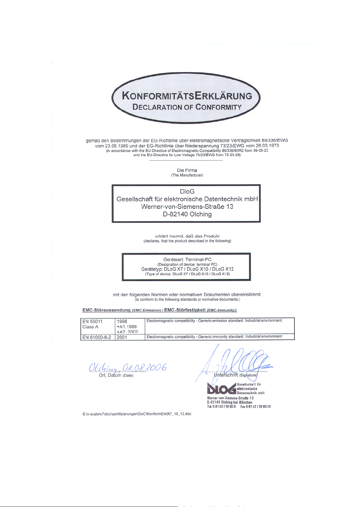
2.6. CE Marking
This product and its authorized peripheral devices comply with all of the requirements for
the CE marking for use at home or in commercial or light industrial applications.
Figure 2.1: CE Marking
2.7. RTTE Directive 1999/5/EC
With regard to the RTTE Directive 1999/5/EC the statements in the declaration of
conformity for the DLoG X device (see page 2 of this handbook) apply.
2.7.1. Special regulations in France
Due to restrictions imposed by the French government, the DLoG X models with
WLAN 802.11b is only permitted for use indoors.
On private property the product is allowed to be used outdoors, however only with
previous approval from France’s Ministry of Defense.
12 Manual DLoG X Series
Page 25

Important safety notices
2.8. FCC user information
2.8.1. Interference declaration of the Federal Communications Commission
This equipment has been tested and found to comply with the limits for a Class A digital
device, pursuant to Part 15 of the FCC Rules. These limits are designed to provide
reasonable protection against harmful interference in a residential installation. This
equipment generates, uses and can radiate radio frequency energy and, if not installed
and used in accordance with the instructions, may cause harmful interference to radio
communications. However, there is no guarantee that interference will not occur in a
particular installation. If this equipment does cause harmful interference to radio or
television reception, which can be determined by turning the equipment off and on, the
user is encouraged to try to correct the interference by one or more of the following
measures:
• Reorient or relocate the receiving antenna.
• Increase the separation between the equipment and receiver.
• Connect the equipment into an outlet on a circuit different from that to which the
receiver is connected.
• Consult the dealer or an experienced radio/TV technician for help.
This device complies with Part 15 of the FCC Rules and with RSS-210 of Industry
Canada.
Operation is subject to the following two conditions:
(1) this device may not cause harmful interference, and
(2) this device must accept any interference received, including interference that
may cause undesired operation.
FCC warning: Any change or modification which is not expressly approved in the
corresponding pages can lead to the withdrawal of the operating license for this device.
In order to comply with the FCC requirements regarding radio frequency exposure from
vehicle-mounted transmission devices the antenna has to be kept at least 20 cm away
from people.
DLoG X Series Manual 13
Page 26

Important safety notices
2.8.2. Transmission of radio frequencies
Use care in airplanes or in clinical/medical areas
Some devices in hospitals and airplanes are not protected from radio frequency
energy. Consequently, do not use the DLoG X device in airplanes or hospitals without
prior authorization. Here use of the DLoG X device is only permitted if authorization is
obtained.
Caution with pacemakers
Do not use the DLoG X device near pacemakers.
The DLoG X device can affect the function of medically implanted devices such as
pacemakers and create interference. Do not place the DLoG X device near such
devices.
Keep a minimum distance of 20 cm between such a device and the DLoG X in order
to reduce the risk of interference.
If you have reason to assume that interference has occurred, then turn the
DLoG X device off and consult a heart expert.
14 Manual DLoG X Series
Page 27
Device description
3. Device description
3.1. General
Thank you for choosing the DLoG X series!
DLoG X-series devices are multi-functional terminals designed for stationary and mobile
use. They are equipped with an Intel PXA270 processor and work with Windows CE 5.0
and Linux embedded operating systems.
Thanks to the robust design (with aluminum housing), the device provides effective
protection against mechanical, electrical and chemical damage and extreme ambient
temperatures. It is designed without an external fan to lower maintenance requirements
The key advantage of the DLoG X series lies in its diverse functionality and compact
design. Various mounting brackets allow installation in the most confined spaces.
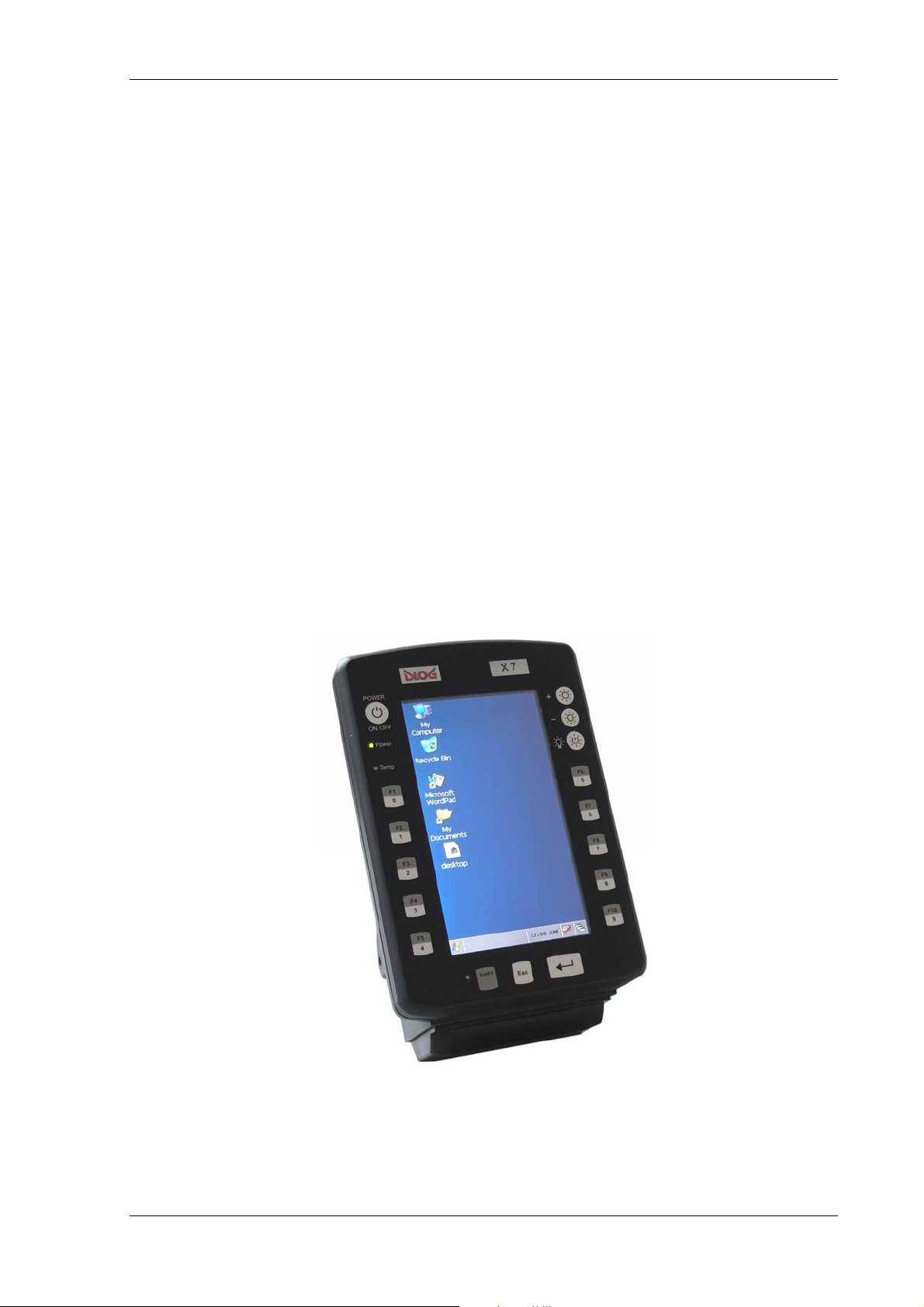
The DLoG X-series is available with various display options.
Figure 3.1: DLoG X 7, vertical display
DLoG X Series Manual 15
Page 28
Device description
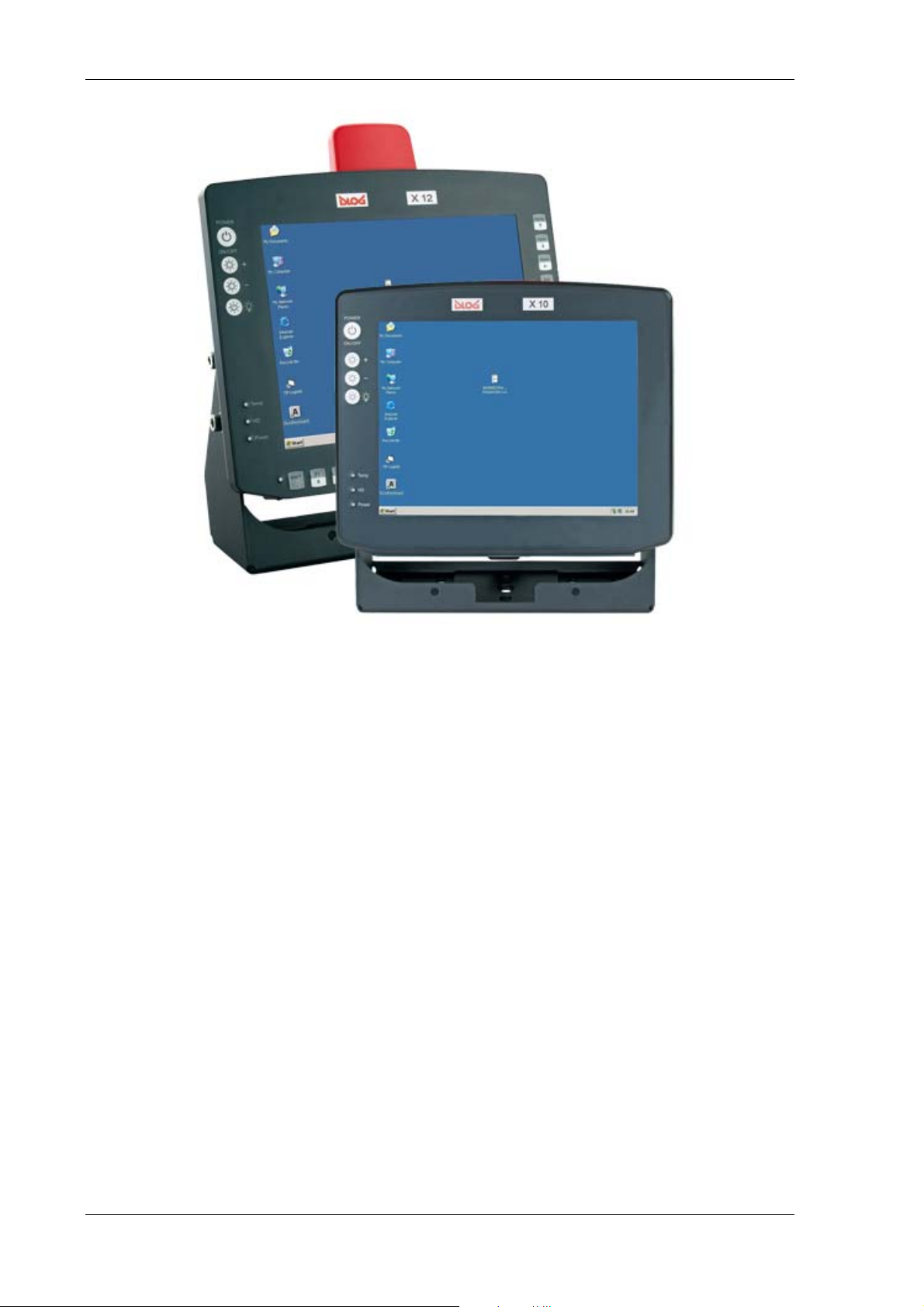
Figure 3.2: DLoG X 10 and DLoG X 12
3.2. Intended usage
The DLoG X 7, DLoG X 10 and DLoG X 12 devices are multifunction terminals for
stationary and mobile use in commercial applications (for example logistics, storage,
manufacturing, automotive).
A different or extraordinary usage is not permitted. For resulting damage the
user/operator of the DLoG X device is solely responsible. This also applies to any
changes you make to the device.
Compliance with the contents of the safety guidelines is particularly important for the
proper use of this device.
16 Manual DLoG X Series
Page 29

Device description
3.3. Models
The information in this manual applies to all current models of DLoG X series.
DLoG X 7 7“ vertical display 7“ horizontal display
4 Shortcut keys x x
17 Shortcut keys x x
DLoG X 10 10,4“vertical display
4 Shortcut keys x
25 Shortcut keys x
DLoG X 12 12,1“vertical display
4 Shortcut keys x
25 Shortcut keys x
Any differences between the devices will be clearly noted in this manual.
3.4. Abbreviations used for devices and accessories
Please note that to save space on the DLoG X device and supplied accessories, the
following abbreviations have been used:
Abbreviation Explanation
+ DC+
- DCIgn Ignition
DLoG X Series Manual 17
Page 30

Device description
3.5. Device description and type identification
3.5.1. Device type plate
The device type plate on the DLoG X series contains the following information:
DLoG X 7
DLoG X 10
DLoG X 12
QWVGA / SVGA Display resolution
DC / AC Type of power supply, the following numbers (1-9)
AV / AH / U The following characters describe device options:
e.g. 24/48 V
Describes the device with display size (7”, 10” or 12”)
indicate the exact type of power supply with input voltage
AV stands for vertical display
AH stands for horizontal display
U stands for the UPS battery option
Input voltage for the DC power supply with nominal
with 1,5/0,75 A
S/N ... The serial number consists of 12 digits and includes:
current
• DLoG specific device code (22 stands for the
DLoG X 7 model range, 32 for the DLoG X 10 model
range, 33 for the DLoG X 12 model range)
• Indication of the week of manufacture (e.g. CW 14)
• Indication of the year of manufacture (e.g. 2005)
• Six digits for internal DLoG identification
18 Manual DLoG X Series
Page 31

Device description
Example of a device type plate:
Figure 3.3: Example of a device type plate
3.6. Technical specifications
3.6.1. System equipment
3.6.1.1. Mechanical
Housing Rugged aluminum-cast housing with integrated heat sink
Hardly combustible plastic parts (acc. to UL94V-0)
Protection class IP54
Upgradeable to IP65
ESD protected
Weight:
DLoG X 7: approx. 2,5 kg
DLoG X 10: approx. 5 kg
DLoG X 12: approx. 5 kg
DLoG X Series Manual 19
Page 32

Device description
Display panel DLoG X 7
7“ QWVGA, 400 cd/m
:
2
at +20 °C, with automatic and manual
brightness adjustment
DLoG X 10
10,4” SVGA, 230cd/m
:
2
with automatic and manual brightness adjustment
10,4” SVGA, 400cd/m
2
with automatic and manual brightness adjustment
DLoG X 12
12,1” SVGA, 400cd/m
:
2
with automatic and manual brightness adjustment
Bottom Cable cover (splash guard)
Optional antenna fitting for WLAN
3.6.1.2. Mainboard
CPU Intel PXA 270 up to 520 MHz
at +20 °C, optional 4-wire touch screen,
bei +20 °C, 4-wire touch screen,
bei +20 °C, 4-wire touch screen,
Cache 32 kB instruction + 32 kB integrated data cache
RAM 64 MB or 128 MB onboard (cannot be retrofitted)
Fully cacheable
SDRAM technology
Flash 64 MB or 128 MB onboard (cannot be retrofitted)
Firmware Microsoft EBOOT
Real-time clock Real-time clock with 3 V Lithium-Battery
20 Manual DLoG X Series
Page 33

Device description
Serial ports 1st Serial port (COM1):
115.200 Baud max (16550A compatible, 64 bytes FIFO)
Full function
Supportsviaalconnectors
ESD level 3 protected (acc. to EN 61000-4-2) – not 20 mA
2nd Serial port (COM2):
115.200 Baud max (16550A/16750 kompatibel, 64 Byte FIFO)
Supports RS-232 on an external 9-pin D-Sub connection
Supports RS-422/RS-485 via adaptor
ESD level 3 protected (acc. to EN 61000-4-2)
Keyboard,
Via USB-Port
mouse
connection
USB connection 1x Host USB connector (USB 2.0 low/full speed) with fuse-
protected USB-A socket, 0.5 A per channel
1x Host USB connector (USB 2.0 low/full speed) with fuseprotected USB-Mini-A socket*, 0.5 A per channel
1x Slave USB connector (only for Microsoft ActiveSync)*
ESD protection, Level 3 (acc. to EN 61000-4-2)
* Alternative (configured with PD.EXE)
Software
compatibility
Microsoft Windows CE
Embedded Linux on request
3.6.1.3. LCD interface
Graphics
controller
Integrated in PXA 270
Shared memory architecture
Internal plug-in connector
Driver installed in Image
DLoG X Series Manual 21
Page 34

Device description
3.6.1.4. Touch interface
Analog touch
controller
10-bit touch controller for 4-wire touch screens
Driver installed
Analog touch
connection
Internal plug-in connector
Interface is ESD level 3 protected (acc. to EN 61000-4-2)
3.6.1.5. PCMCIA interface
PCMCIA
controller
Integrated in PXA 270
Driver installed in Image
PCMCIA slot 1 x type 1, accessible via the side of the device
3.6.1.6. CompactFlash interface
CF controller Integrated in PXA 270
Driver installed in Image
CF slot 1 x type 1, accessible via the side of the device
3.6.1.7. SD/SDIO interface
SDIO controller Integrated in PXA 270
Driver installed in Image
SDIO slot 1 x type 1, accessible via the side of the device
22 Manual DLoG X Series
Page 35

Device description
3.6.2. Power supply / Power packs
3.6.2.1. DC Power packs (internal)
(The device model is displayed on the device label)
DC power pack
24/48 VDC
60 W internal
Type: DC-2
DC power pack
24/48 VDC
100 W internal
Type: DC-3
DC power pack
24/48 VDC nominal (down to 11 V for 20 s max.)
Voltage range: 18 to 59 VDC
Bridges power outages of 5 ms
Electrically-isolated
Maximum output 60 W
Switch off automatic (option)
Heating (option)
Withstands bursts up to 2 kV
Primary nominal current 3,7 A
Connection only to SELV circuit
1)
12/48 VDC nominal (down to 11 V for 20 s max.)
Voltage range: 18 to 59 VDC
Bridges power outages of 5 ms
Electrically-isolated
Maximum output 100 W
Switch off automatic (option)
Heating (option)
Withstands bursts up to 2 kV
Primary nominal current 6,2 A
Connection only to SELV circuit
2)
12 VDC nominal (down to 6 V for 20 s max.)
12 VDC
100 W internal
Type: DC-1
Voltage range: 9 to 16 VDC
Bridges power outages of 5 ms
Electrically-isolated
Maximum output: 100 W (9 to 16 VDC), 80 W (6 to 9 VDC)
Switch off automatic (option)
Heating (option)
Withstands bursts up to 2 kV
Primary nominal current 15 A
Connection only to SELV circuit
3)
DLoG X Series Manual 23
Page 36

Device description
DC power pack
24/48 VDC nominal (down to 10 V for 20 s max.)
24/48 VDC
40 W internal
Type: DC-6
DC power pack
12/24 VDC,
30 W internal
Type: DC-7
Voltage range: 18 bup to 60 VDC
Bridges power outages from 5 ms (24 VDC)
Electrically-isolated
Maximum output: 30 W
Withstands bursts up to 2 kV
Primary nominal current 1,5 / 0,75 A
Connection only to SELV circuit
4)
12/24 VDC nominal (down to 5 V for 20 s max.)
Voltage range: 9 to 36 VDC
Minimum start-up voltage 9 VDC
Bridges power outages from 5 ms (12 VDC)
Electrically-isolated
Maximum output: 30 W
Withstands bursts up to 2 kV
Primary nominal current 3,0 / 1,5 A
Connection only to SELV circuit
5)
1) to 5)
The SELV circuit is a secondary circuit that is designed and protected in such a way
that its voltages will not exceed a safe value if the device is properly used or a single
error occurs.
24 Manual DLoG X Series
Page 37

Device description
3.6.3. AC power packs
Low voltage networks
Devices in the X Series that have an AC power pack should only be
connected to TN and TT networks. IT networks are not permitted as
dangerous electric shocks cannot be ruled out here.
AC power pack
110 V / 230 V, 50 to 60 Hz
110/230 VAC,
30 W internal
AC power pack
110/230 VAC, 100
W internal
Rechargeable
buffer battery
(optional)
Maximum output 30 W
Electrically-isolated
Withstands bursts up to 4 kV
Primary nominal current 0,3 A
Important: You cannot access the fuse externally or replace it.
110 V / 230 V, 50 to 60 Hz
Maximum output 100 W
Electrically-isolated
Withstands bursts up to 4 kV
Primary nominal current 1 A
Fuse type: T1.25AL250V
Only for DLoG X 10 and DLoG X 12:
To temporarily bridge power outages
Lithium polymer rechargeable battery 11.1 V
Bridging time depends on the configuration
approx. 15 min. (longer if backlight is switched off)
DLoG X Series Manual 25
Page 38
Device description
3.6.4. Maximal power available for peripheral devices
Power adaptor Power
DC-6 15 W (30 W 24/48 V)
DC-7 15 W (30 W 12/24 V)
DC-5 50 W (70 W 24/48 V)
DC-4 50 W (70 W 12 V)
DC-2 40 W
AC-3 15 W
AC-1 80 W
3.6.4.1. Power adaptor fuses
Power adaptor Fuse type
DC-5 5x20 mm T 12,5 A / 250 V
DC-6 5x20 mm T 4,0 A / 250 V
DC-7 5x20 mm T 10 A / 250 V
AC-3 Integrated fuse, not replaceable by user
3.6.4.2. Environmental conditions
Operating
temperature
All specifications in accordance with EN 60068-2-1/2
DLoG X 7: -30 °C to +50 °C
(Start/Switch on temperature >= -25 °C)
DLoG X 10 and X 12: 0 to +50 °C
DLoG X 10 and X 12 with heating option: -30 °C to +50 °C
Storage
temperature
All specifications in accordance with EN 60068-2-1/2
DLoG X 7: -35 °C to +65 °C
DLoG X 10 and X 12: -20 °C to +60 °C
Relative
humidity
In accordance with EN 60068-2-3
10 % to 90 % at 40 °C, non-condensating
26 Manual DLoG X Series
Page 39

Device description
Resistance to
mechanical
shock and
vibrations
3.6.5. Test marks
CE EN 55022 Class A
Class 7M3 in accordance with EN 60721-3-5 1998 (ground
vehicles)
1.5 hours 3 g effective noise and 300 vibrations with 30 g
peaks or US Highway Truck according to MIL-STD 810F:
2000 (Department of Defense), 3 hours 1 g effective noise
and 600 vibrations with 20 g peaks
EN 61000-3-2, EN61000-3-3, EN 61000-6-2
IEC 60950-1, EN 60950-1, UL 60950-1
DLoG X Series Manual 27
Page 40

Device description
3.6.6. Dimensions
3.6.6.1. Dimensions DLoG X 7
Front view
Dimensions without add-ons (in mm):
Figure 3.4: Dimensions DLoG X 7 front view
28 Manual DLoG X Series
Page 41

Device description
Side view
Dimensions without add-ons (in mm):
Figure 3.5: Dimensions DLoG X 7 side view
DLoG X Series Manual 29
Page 42
Device description
Top view
Dimensions without add-ons (in mm):
Figure 3.6: Dimensions DLoG X 7 top view
30 Manual DLoG X Series
Page 43

Device description
3.6.6.2. Dimensions DLoG X 10
Front view
Dimensions without add-ons (in mm):
Figure 3.7: Dimensions DLoG X 10 front view
DLoG X Series Manual 31
Page 44

Device description
Side view
Dimensions without add-ons (in mm):
Figure 3.8: Dimensions DLoG X 10 side view
32 Manual DLoG X Series
Page 45
Device description
Top view
Dimensions without add-ons (in mm):
Figure 3.9: Dimensions DLoG X 10 top view
DLoG X Series Manual 33
Page 46
Device description
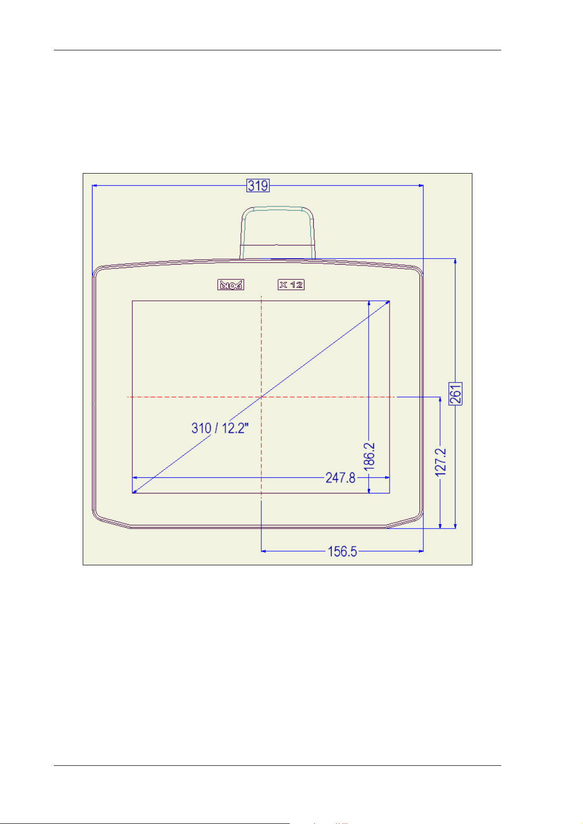
3.6.6.3. Dimensions DLoG X 12
Front view
Dimensions without add-ons (in mm):
Figure 3.10: Dimensions DLoG X 12 front view
34 Manual DLoG X Series
Page 47
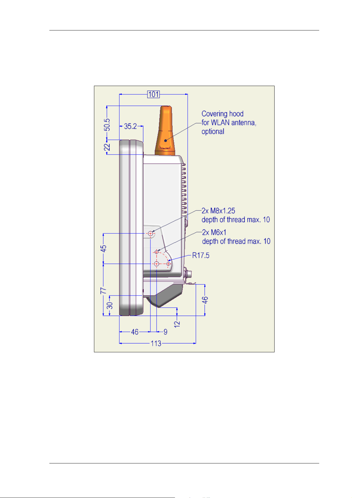
Device description
Side view
Dimensions without add-ons (in mm):
Figure 3.11: Dimensions DLoG X 12 side view
DLoG X Series Manual 35
Page 48

Device description
Top view
Dimensions without add-ons (in mm):
Figure 3.12: Dimensions DLoG X 12 top view
36 Manual DLoG X Series
Page 49

Device description
3.6.7. VESA drill holes
3.6.7.1. VESA drill holes DLoG X 7
This drawing indicates the DLoG X 7’s VESA drill holes:
Figure 3.13: VESA drill holes DLoG X 7
DLoG X Series Manual 37
Page 50
Device description
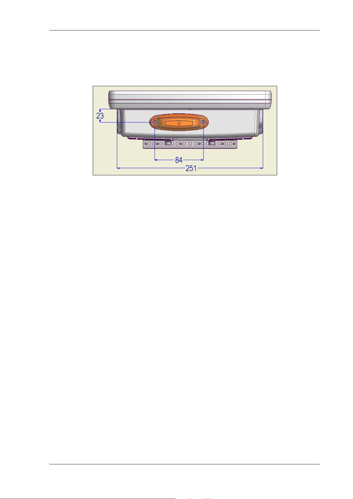
3.6.7.2. VESA drill holes DLoG X 10
This drawing indicates the DLoG X 10’s VESA drill holes:
Figure 3.14: VESA drill holes DLoG X 10
38 Manual DLoG X Series
Page 51

Device description
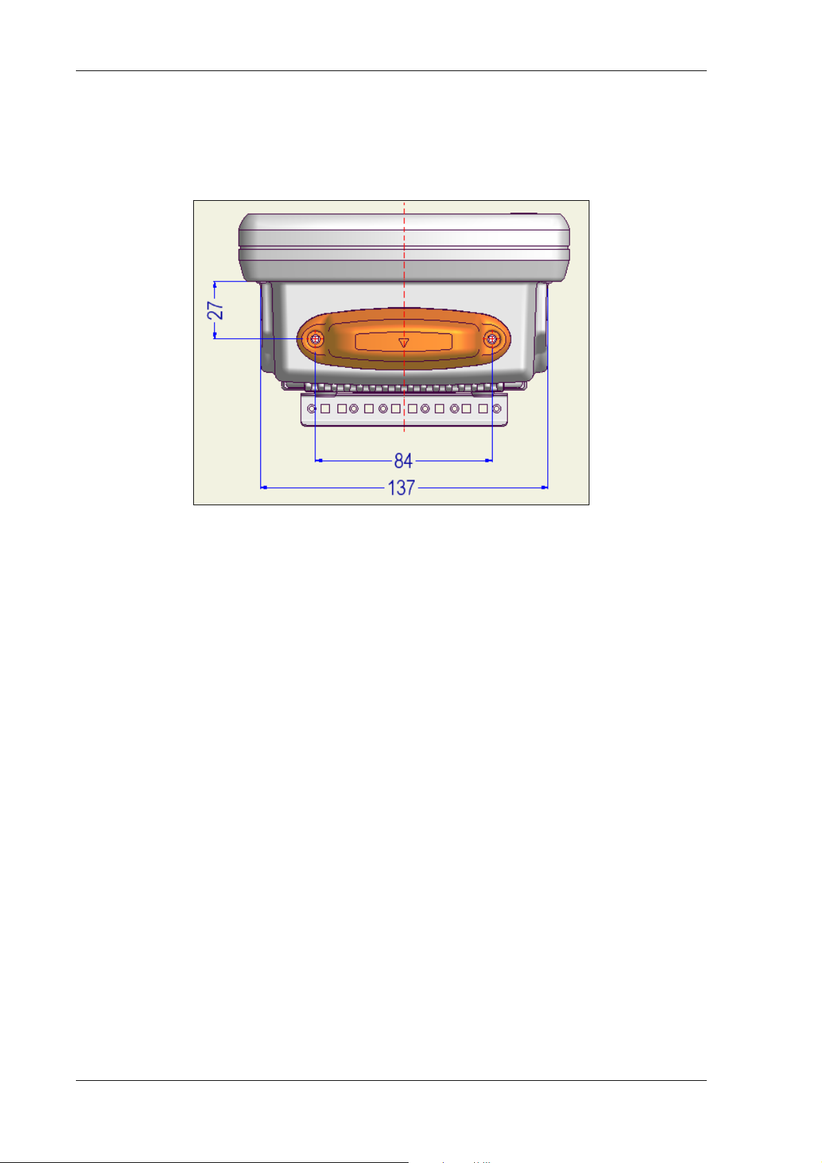
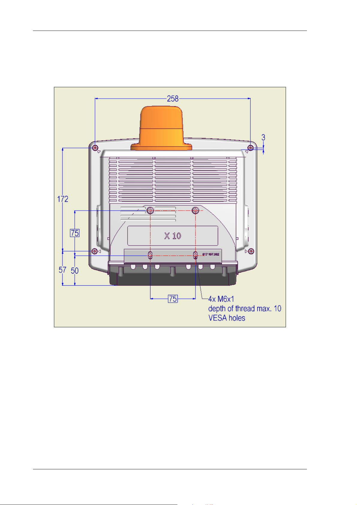
3.6.7.3. VESA drill holes DLoG X 12
This drawing indicates the DLoG X 12’s VESA drill holes:
Figure 3.15: VESA drill holes DLoG X 12
DLoG X Series Manual 39
Page 52

Unpacking the device
4. Unpacking the device
4.1. Scope of delivery
The delivery includes at least the following components:
• The ordered DLoG X model
• The ordered assembly set (if ordered)
• One cable cover (standard = IP54; optional = IP65)
• One connecting cable for DC connection
• One printed manual per delivery
Please verify the delivery contents immediately on receipt.
4.2. Packaging
The packaging material has been selected to optimally protect your device while
simultaneously offering the best possible ecological compatibility. We therefore kindly
request that you store the original packaging material or ensure it is used for another
suitable purpose such as transporting the unit or returning shipment.
If you repack the device, please ensure that the cling wrap in the
cardboard frame is positioned towards the front of the device so
that it can provide the proper protection.
4.3. Returning your device
Due care was exercised when putting together the contents of your delivery and
dispatching your device. Nevertheless, if you still have cause for complaint, please
complete the form included in the appendix.
Should you need to return the device, please use the original packaging.
40 Manual DLoG X Series
Page 53
Initial operation
5. Initial operation
Before operating the unit for the first time, carefully read the Safety
notices at the start of this manual.
5.1. Cooling through the supply of fresh air
The DLoG X devices employ a passive cooling concept whereby the waste heat
generated inside the device is emitted from the surface of the housing. For this system to
function properly, sufficient fresh air circulation is required.
Never install the system in a closed environment where the cooling air is unable to
dissipate accumulated heat to the outside.
If the DLoG X device is not able to draw in fresh cooling air, this
may cause overheating and severe damage to the unit.
Be sure to comply with the maximum ambient temperature to
guarantee correct operation (as specified in chapter 3.6 Technical
specifications).
DLoG X Series Manual 41
Page 54
Initial operation
5.2. External connectors DLoG X 7
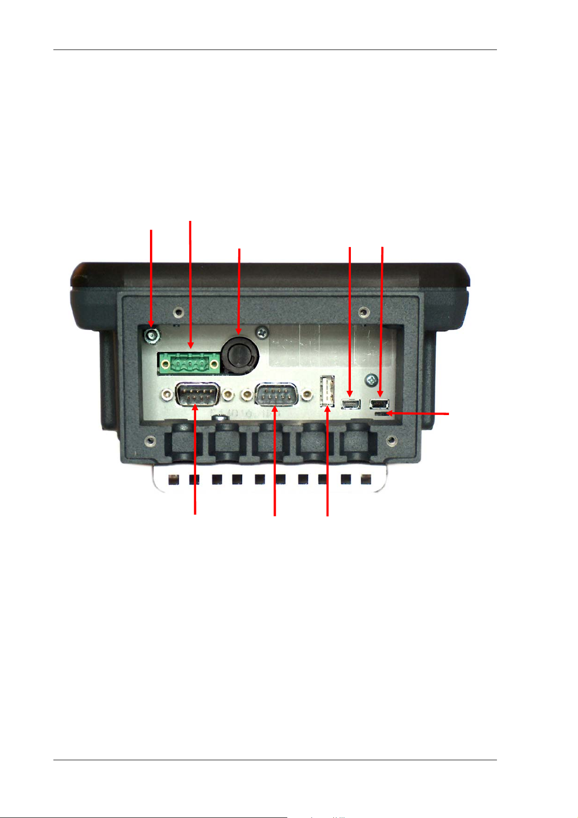
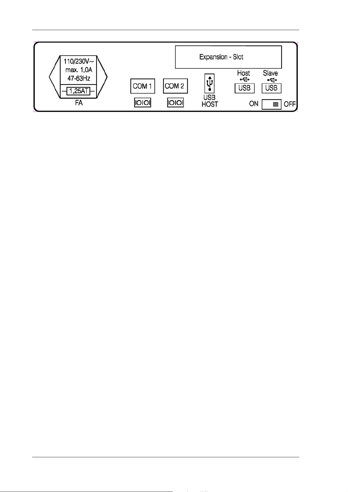
5.2.1. Standard connectors
This section describes the DLoG X 7 standard plug-in connectors.
Power
supply
Grounding bolt
with M4 thread
Fuse holder USB Host USB Client
COM1 COM2 USB Host
Figure 5.1: External connectors on the DLoG X 7, DC version
5.2.2. Optional connectors
Read more about the optional connectors in the following sections:
12.2
Slide
switch
42 Manual DLoG X Series
Page 55

Initial operation
COM2 Options
13 Audio (Option)
DLoG X Series Manual 43
Page 56

Initial operation
5.2.3. Power pack models
Figure 5.2: External connectors DLoG X 7, DC 12/24 V, 30 W
Figure 5.3: External connectors DLoG X 7, DC 24/48 V, 30 W
Figure 5.4: External connectors DLoG X 7, AC 110/230 V, 36 W
44 Manual DLoG X Series
Page 57

Initial operation
5.2.3.1. DC voltage supply connector
Version: Phoenix Combicon, 3pol.
Before operating the unit, carefully read all the Important safety
notices at the beginning of this manual. If you do not follow the
safety instructions provided, the system may become damaged and
all present or future guarantee and liability claims will be voided.
External view:
Figure 5.5: DC connector (external view)
Explanation: Ignition on means that a control signal has to be routed to this connection
(e.g., ignition of a vehicle) that matches the supply voltage level and can supply at least
2 W. The signal reference is DC-.
DLoG X Series Manual 45
Page 58

Initial operation
5.3. External connectors DLoG X 10 and DLoG X 12
5.3.1. Standard connectors
The standard connectors correspond to the
5.3.2. Optional connectors
Read more about the optional connectors in the following sections:
12.2
External connectors DLoG X 7.
46 Manual DLoG X Series
Page 59

Initial operation
COM2 Options
13 Audio (Option)
5.3.3. Power pack models
Figure 5.6: External connectors DLoG X 12 / X 12, DC 12 V, 100 W
Figure 5.7: External connectors DLoG X 12 / X 12, DC 24/48 V, 100 W
Figure 5.8: External connectors DLoG X 12 / X 12, DC 24/48 V, 60 W
DLoG X Series Manual 47
Page 60
Initial operation
Figure 5.9: External connectors DLoG X 12 / X 12, AC 110/230 V, 100 W
48 Manual DLoG X Series
Page 61

Initial operation
5.4. Connecting/Disconnecting external devices
5.4.1. USB connection
When connecting or disconnecting USB devices, be sure to note the maximum current
that the USB connections can supply.
The cable should also be fitted with a strain relief.
No other specific precautions are required for the DLoG X devices.
5.4.2. COM connection
Before connecting or disconnecting devices to a COM port on the DLoG X device, you
must first disconnect the DLoG X device from the power supply.
5.4.2.1. Initial operation with external peripheral devices
Before connecting or disconnecting peripheral devices to a COM
port, the DLoG X device must be disconnected from the power
supply. Otherwise, both the DLoG X device and the connected
device can be seriously damaged!
Make sure that external peripheral devices with their own power
supply are switched on at the same time or after you start the
DLoG X device. If this is not possible, you need to make sure that
the DLoG X device is adequately protected from any power
leakages caused by the external devices.
DLoG X Series Manual 49
Page 62

Initial operation
Always shut down the DLoG X device as follows:
1. If your DLoG X device has automatic switch off, shut down the device using the
ignition input.
2. If your device has an activated <Power> button, shut it down using this button.
3. Remove the cable cover.
4. Isolate the supply voltage (tighten the plug).
The DLoG X device is shut down once the Power LED switches off!
Powering up the DLoG X device
Only power up the DLoG X device when all devices have been connected and the
DLoG X device has been properly closed (remember the cable cover).
Check that the plug for the power supply and the plug in the COM jacks (if any) are
screwed on.
Otherwise, you may damage the DLoG X device.
50 Manual DLoG X Series
Page 63

Initial operation
5.5. Powering up the device
To power up the DLoG X device, connect it to an appropriate power supply and,
depending on the model, press either the <Power> button or the ignition signal.
5.5.1.1. Peripheral devices/equipment
If peripheral devices/equipment are used, they must be connected before you switch on
the DLoG X device.
Only power up the DLoG X device after all external devices have been connected.
Make sure there is a suitable disconnecting device such as a power
switch or circuit breaker in the power supply circuit.
5.6. Removing the protective film from the front
The front of the DLoG X device is protected during transport by a transparent film. This
film should remain on the front during assembly to avoid damage to the front surface.
1. Only remove the film once all of the assembly work has been completed.
2. Take the foil off slowly and carefully, in order to avoid static loading. To high
tension can damage the terminal.
DLoG X Series Manual 51
Page 64

Initial operation
5.7. Protecting the TFT display from the memory effect
The TFT display of the DLoG X device has to be protected from the burning in of a
motionless image. An image that has remained motionless for too long can cause
irreversible damage to the display.
With TFT displays there no cathode rays burning in an afterimage as in old TV sets or
monitors, but TFT displays still have a “memory effect”. This is because with a still image
the liquid crystal molecules align themselves in a certain way and become inert if they
are not moved.
Like burning in the effect is irreversible, but can be avoided by regularly turning off the
display.
• Define in the power management center of the utilized operating system that the
display of the DLoG X device should be turned off when no user input occurs. A
motionless image can stay on the display for a maximum of 12 hours. After more
than 12 hours there is the risk of the memory effect.
Important for the lifespan of the backlighting:
Choose a turn off time that is definitely not too short (not less than 30 min) since frequent
turning on of the backlighting will noticeably reduce its lifespan. This particularly applies
at low temperatures.
5.8. Installing Application Software
Depending on the application, install the software via WLAN, Bluetooth, or the USB client
interface (ActiveSync).
52 Manual DLoG X Series
Page 65

Initial operation
5.9. Important Software Settings
5.9.1. Wireless network
Depending on the optional equipment and specific use of the DLoG X device,
settings/access data must be defined for wireless networks such as WLAN.
For information on WLAN settings, refer to online help for the menu
Start | Settings | Network Dial-Up Connections.
It is important to note that these settings are permanently saved when you:
• Enter the command saveregistry in the Windows menu Start | Run | open
and acknowledge with OK.
5.9.2. Touch screen calibration
The DLoG X is supplied pre-calibrated. In order to make fine calibrations:
1. Press the touch screen until a shortcut menu appears (functions like a right mouse
button).
2. Open the menu Admin Tools.
3. Open the Calibration menu option and click on Recalibrate.
Fine calibration now commences.
To permanently save this setting, the saveregistry command must be executed:
1. Press the touch screen until a shortcut menu appears (functions like a right mouse
button).
2. Open the menu Admin Tools.
3. Click on the Saveregistry function.
4. Press OK.
The fine calibration has now been permanently stored.
DLoG X Series Manual 53
Page 66
Initial operation
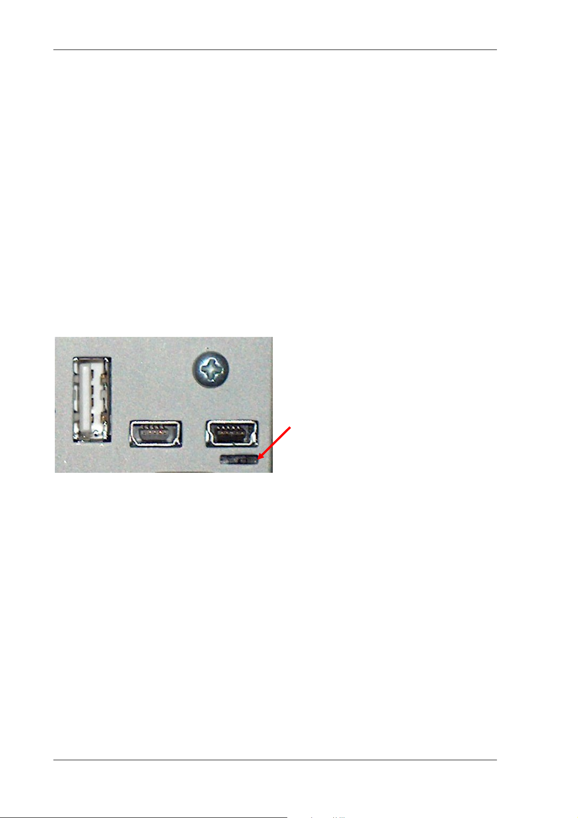
5.10. After extended non-use
The DLoG X device is delivered with the RTC battery switched off by default. The RTC
battery powers the clock in the event of power failure (power reserve).
The RTC battery is switched on and off by means of a sliding switch located at the
bottom right of the DLoG X device connector bay.
The sliding switch must be switched on before starting up the device.
• To do this, gently push the switch to the left with a small screwdriver (with the
display upwards).
• If the device is not going to be used for more than two weeks, the battery should be
switched off to prevent a total discharge and thus battery damage.
Sliding switch on the right:
RTC battery off
Sliding switch on the left:
RTC battery on
Figure 5.10: Sliding switch
54 Manual DLoG X Series
Page 67

Accessories
6. Accessories
This section covers the accessories available for the DLoG X-series:
• Keyboard
• Mouse
• USB Stick
• Scanner
• WLAN Cards
• CompactFlash
• Adapter cable
Use only accessories for the DLoG X-series that have been tested
and approved by DLoG GmbH. You can find out about approved
items from your DLoG sales office.
DLoG X Series Manual 55
Page 68

Accessories
6.1. Keyboard
You can connect a USB keyboard to the DLoG X device with a USB-A or USB Mini-A
connector.
6.1.1. SMALL keyboard
A mountable SMALL keyboard (German/English; protection class IP 65) is available for
the DLoG X series.
Figure 6.1: SMALL keyboard
SMALL keyboards available from DLoG:
• Desktop SMALL keyboard, English and German
• Add-on version SMALL keyboard, English and German, this add-on version can be
attached to a stationary or mobile mounting bracket with a mounting kit.
56 Manual DLoG X Series
Page 69

Accessories
6.1.2. 24-key keypad
A 24-key keypad which can be mounted onto the device, with a protection class IP 65 is
available for the DLoG X devices.
For the DLoG X 7, this keyboard is only available for a device with a vertical display. The
keyboard is not made to be used with a horizontal display.
For the DLoG X 10 and X 12, at he 24-key keyboard can be attached to the right side of
the device.
Figure 6.2: 24-key keypad
DLoG X Series Manual 57
Page 70

Accessories
6.2. Mouse
You can connect a USB mouse to the DLoG X device using a USB-A or USB Mini-A
connector. The system only supports two mouse buttons.
6.3. USB Stick
You can connect a USB stick to the DLoG X device with a USB-A or USB Mini-A
connector.
6.4. Scanners
You can connect scanners via USB or serial port. If connected to COM1, the scanner can
be powered through the port (optional). Be sure to only use scanners that have been
approved by DLoG.
6.5. WLAN cards (PC cards)
WLAN cards are inserted in the PC card slot or the CF card slot.
Generally, you can only install drivers for WLAN cards that have been approved by
DLoG.
6.6. CompactFlash
CompactFlash is currently included in the standard package.
6.7. Adapter cables
Various adapter cables are available, for example for changing between USB Mini-A to
USB A.
58 Manual DLoG X Series
Page 71

Mounting
7. Mounting
7.1. Options for mounting the device
Risk of injury
The unit could fall during transit or installation/mounting and cause
injury. Always ensure that there are two persons available when
installing or removing the device.
Pay careful attention to the Important safety notices included at the
start of this manual.
The DLoG X series can be mounted in a variety of ways:
• It can be positioned horizontally on a desk or mounted on a steering wheel and
vehicle console.
• Wall mounts are also available for mounting the unit on machines and operating
panels.
• Roof mounting is also possible, for example under the vehicle roof.
Depending on the vibration resistance and pivoting demands, mounting brackets, clamp
foots or RAM mount elements can also be used to attach the device. Please contact
your DLoG sales office to find out more about the whole range of installation options on
offer.
7.2. Observe and retain the mounting instructions
Please follow the installation/mounting instructions included with assembly kit when
installing your DLoG X device.
Please make sure that you retain the instructions. Pay careful attention to the important
safety notices included in the beginning of this manual.
DLoG X Series Manual 59
Page 72

Mounting
7.3. Mechanical dynamic loading
Since the DLoG X device is a weighted structure, it is invariable that the unit will be
subject to mechanical dynamic effects. Therefore optimizing the mounting can be very
helpful. Please refer to
Appendix C: Mechanical dynamic loading.
7.4. Power supply
An integrated, electrically isolated AC or DC power supply is available for all devices of
the DLoG X-series.
The power adaptor is designed to fulfill the requirements for the full range of operating
temperatures. In addition, you can operate additional modules and/or external devices.
7.4.1. DC power packs
DLoG X devices are available with various integrated DC power supply units.
DLoG X 7:
• DC power pack with 12/24 VDC input voltage, maximum output 30 W
• DC power pack with 24/48 VDC input voltage, maximum output 30 W
DLoG X 10 and X 12:
• DC power pack with 24/48 VDC input voltage, maximum output 100 W
• DC power pack with 24/48 VDC input voltage, maximum output 60 W
• DC power pack with 12 VDC input voltage, maximum output 100 W
DLoG X devices must only be connected to a SELV6) (Safety Extra
Low Voltage) circuit. Ensure that there is a suitable disconnecting
device such as a power switch or circuit breaker in the power
supply circuit. Ensure that the disconnecting device isolates all
supply voltage lines. Furthermore, the DC+ connecting cables must
be protected by a fuse (16 AT max). The ignition connecting cables
must be protected by a fuse of the following type: 5x20 mm T
125 mA L / 250 V, for example, a Wickmann 195-125 mA / 250 V.
60 Manual DLoG X Series
Page 73
Mounting
6)
The SELV circuit is a secondary circuit that is designed and protected so that its
voltages will not exceed a safe value both when operating correctly or if a single error
occurs.
7.4.2. AC power packs
DLoG X devices are available with various integrated AC power supply units.
DLoG X 7:
• AC power pack with 110/230 VAC input voltage , maximum output 30 W
DLoG X 10 and X 12:
• AC power pack with 110/230 VAC input voltage, maximum output 100 W
Ensure that there is a suitable disconnecting device such as a
power switch or circuit breaker in the power supply circuit.
Ensure that the disconnecting device isolates all supply voltage
lines.
7.4.3. Installing connecting cables
Ue the connecting cables supplied to connect the DLoG X device to the power supply.
Make sure that the connecting cables are laid without kinks and are protected.
DLoG X Series Manual 61
Page 74

Mounting
7.5. Vehicle applications (such as forklifts)
Pay special attention to the various electrical potentials when installing the unit on a
vehicle (such as a forklift). In the DLoG X devices, the logic ground and the shield ground
are firmly linked.
The “logic ground” is the earth line (GND) for all of the internal electrical components,
such as the hard drive and the CPU. Cable shielding, the housing and the ground
conductor (in AC-powered units) are connected to the shield ground.
Carefully read the following warnings!
• When connecting a DLoG X device, make sure that the on-board voltage of the
vehicle and the terminal input voltage are compatible.
• The terminal input voltage is indicated on the device type plate and on the label for
the pin configuration.
• Some forklifts have a frame that is connected to DC+. Therefore, the DLoG X frame
is also DC+. However, if you use peripheral devices that supply DC– to the
DLoG X device via an interconnector (such as a DC– serial interface), this will
cause a short circuit. This will inevitably lead to malfunctions or even a total system
failure.
• Please be aware that, for example, on forklifts with inverter drives, malfunctions can
occur in the power supply that are beyond the potential tolerance of the DLoG X
device. In such cases the DLoG X device can be irreparably damaged. In such
circumstances it may be necessary to install a line filter. If required, contact your
DLoG sales representative.
62 Manual DLoG X Series
Page 75

Mounting
7.5.1. DC terminals
In DC-powered devices, always attach ring tongue on the supply voltage cable to the
ground bolt situated on the connector bay.
Ground
bolt
Figure 7.1: Position of the ground bolt
• The other end of the yellow-green supply voltage cable has to be connected to the
vehicle’s chassis
• Make sure that the DLoG X device’s connecting cable is terminated as close to the
battery as possible. Connecting the DLoG X device to large electrical loads, such as
converters for the forklift motor may result in random restarts, malfunctions and/ or
irreparable equipment damage to the system.
• If you want to connect devices fed by other power sources to the DLoG X device
(e.g. certain printers), make sure to power up the peripheral devices at the same
time or after the DLoG X device. Otherwise, you may encounter start-up problems,
malfunctions or even irreparable damage to your system
DLoG X Series Manual 63
Page 76

Mounting
7.6. Cable cover (Splash guard)
For safety reasons, the supplied cable cover for the external ports
must be installed prior to using the DLoG X device.
7.6.1. Protection class IP65
In order to comply with protection class IP65, please use the optionally available IP65
assembly kit from DLoG. Please observe the installation instructions included with this
assembly kit.
After finishing the mounting process the cables must be affixed using the included strain
relief rail or strain relief clamp.
7.6.2. Protection class IP54
To ensure that the DLoG X devices continues to conform to this protection category,
proceed as follows:
1. Place the cables connected to and from the device next to each other. Avoid
crossing the cables.
2. Attach the cables to the strain relief rail using the enclosed strain relievers or strain
relief clamp. Ensure that the cables are attached exactly where the cable cover’s
cable opening is located.
3. Now attach the sealing ends onto the cables.
Take care not to damage the opening seal of the cable cover!
It should be possible to attach the cable cover to the cable duct
without using force.
The neck collar screws should be screwed firmly, preferably
diagonally and always using 5 rotations.
The screws need to be retightened after 2 days.
64 Manual DLoG X Series
Page 77

Operation
8. Operation
8.1. Touch screen operation
All DLoG X devices are available with the option of a resistive touch screen.
The touch screen surface should be kept free of dirt, sand, stones, and similar materials,
in order to prevent damage.
Inappropriate operation of the screen, for example by using sharp
objects such as screwdrivers, will irreparably damage the touch
screen.
Recommended operation of the resistive touch screen:
• Clean, dry fingers
• Clean, dry, soft gloves
• Suitable touch screen pencils (plastic or wood, rounded tip, maximum 4 H
hardness)
Resistive touch screens may NOT be operated with:
• Ball point pens, pencils, or other inappropriate writing implements
• Unsuitable touch-screen pencils (harder than 4 H)
• Hand tools of any kind (such as a screwdriver)
• Sharp objects (knives, scalpels, etc.) that could damage the touch surface.
8.1.1. Dirty touch screen surface
If the touch surface is dirty, it must be cleaned before operation. Clean the touch screen
according to the instructions in Chapter
utensils, never use sulfurous cleaners).
DLoG X Series Manual 65
16.2 Cleaning the touch screen (Never use sharp
Page 78

Operation
8.2. Operating controls DLoG X 7
There are a number of indicator lamps and controls on the front of the DLoG X 7.
Available models:
• Standard configuration with 4 keys
• Extended configuration with 17 keys
8.2.1. Horizontal/vertical versions
The DLoG X 7 is available in two versions for either horizontal or vertical mounting.
8.2.2. Standard configuration (4 keys)
The standard configuration of the DLoG X 7 only has one button and two indicator lamps
on the left and three keys on the right of the front side. This configuration is available for
both horizontal and vertical mounting.
Figure 8.1: DLoG X 7 vertical, 4 keys
66 Manual DLoG X Series
Page 79
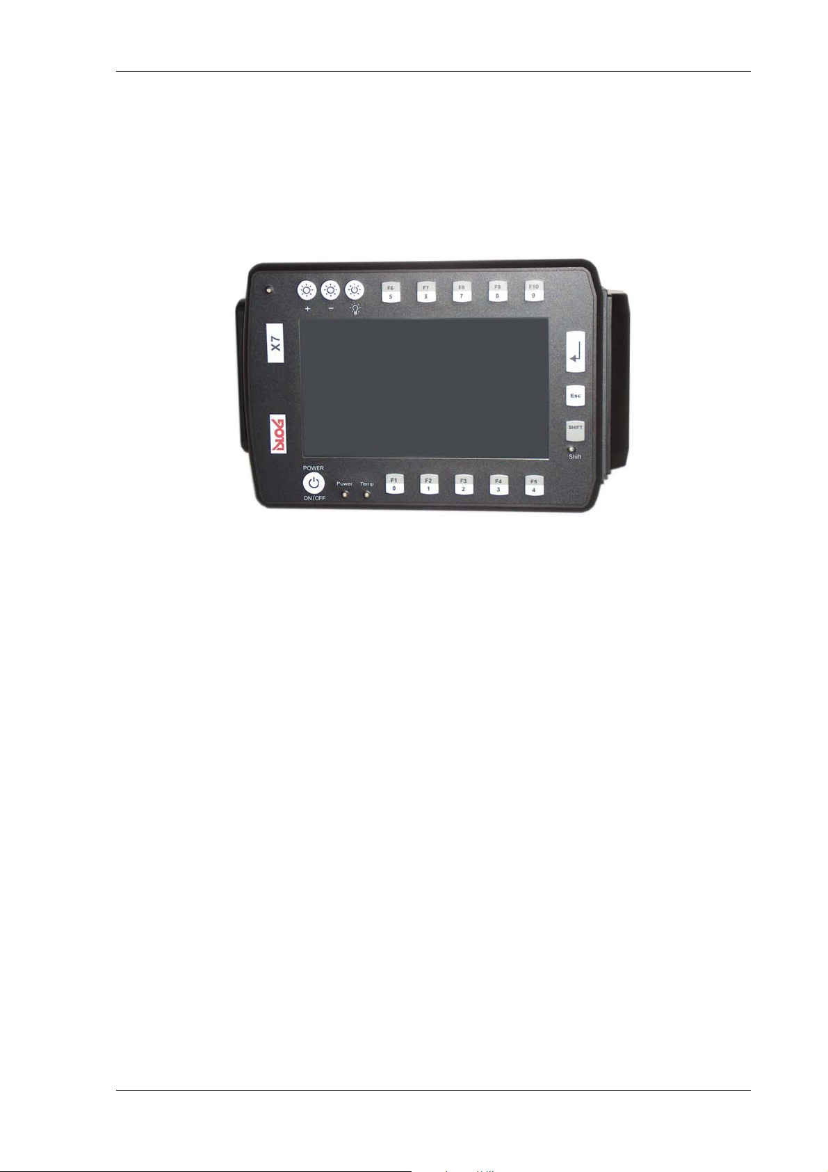
Operation
8.2.3. Extended configuration (17 keys)
Alternatively, you can select an extended configuration with 17 keys and three indicator
lamps. Once again, this configuration is available for both mounting options
(horizontal/vertical).
Figure 8.2: DLoG X 7 horizontal, 17 keys
8.2.4. Brightness control
Note for units featuring brightness control: Even after manually turning off the display
lighting, the DLoG X 7 will continue to respond to input via the keyboard, mouse or touch
panel. This means that you can continue to enter commands and data even if the display
lighting is off.
DLoG X Series Manual 67
Page 80
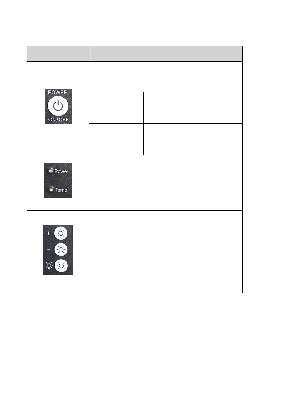
Operation
8.2.5. Front controls (standard)
Indicator/control Explanation
<Power> button to switch the DLoG X 7 on/off:
This button has been preconfigured by DLoG to provide the
following functions by default:
DLoG X 7
with automatic
switch-off
<Power> button is not used for powering up
the unit. If the button is pressed before the
shutdown delay time has elapsed, the unit
is powered down immediately.
DLoG X 7
without
automatic
switch-off
<Power> button is used to power up the
unit. If the button is pressed while the unit is
operating, this results in a HARD shutdown.
This may lead to data loss!
Power (green LED): indicates connection to a power supply
Temp (red LED) indicates an excessively high or low
temperature inside the unit
<+> button for manual brightness control
<-> button for manual brightness control
Switching the backlight on/off or toggling between manual
and automatic brightness control
68 Manual DLoG X Series
Page 81
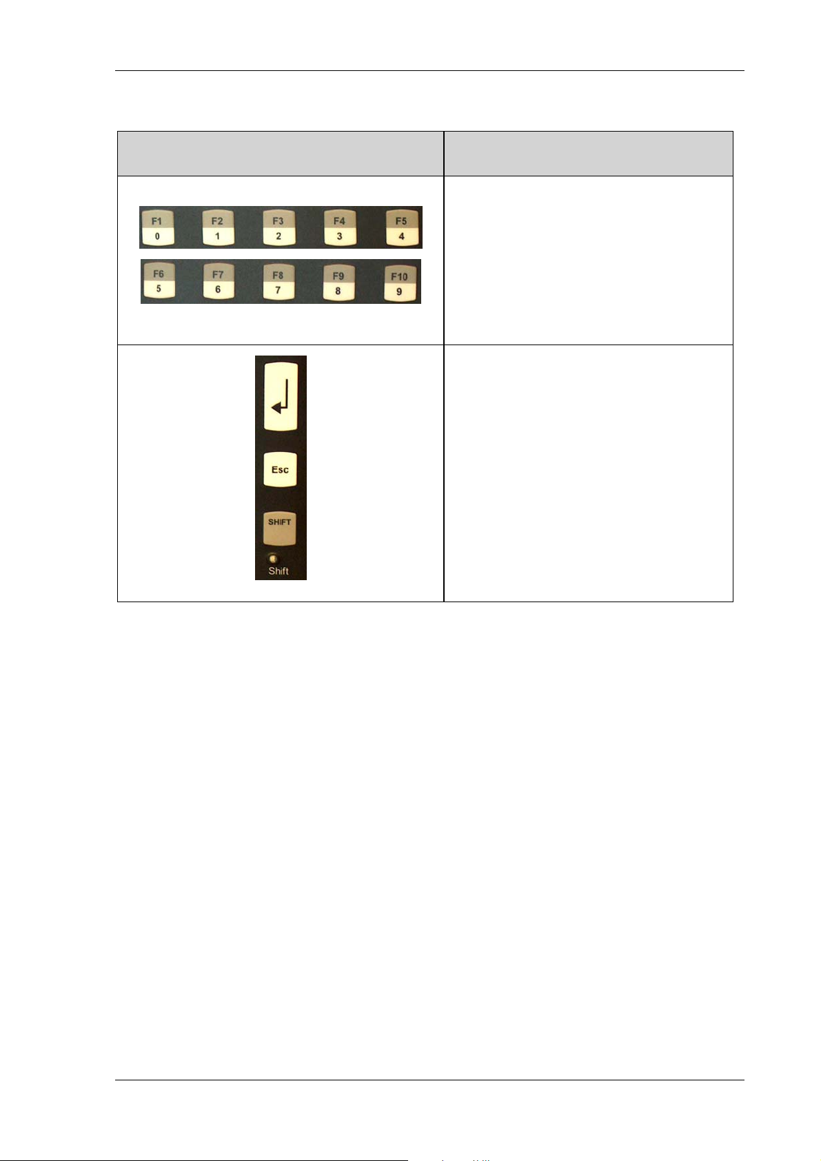
Operation
8.2.6. Front controls (extended)
Indicator/control Explanation
These buttons have two functions:
• 0 to 9
• When the <Shift>-key is held:
Function keys <F1> to <F10>
<Enter> key
<Esc> key
<Shift> key
Status indicator of the <Shift> key
DLoG X Series Manual 69
Page 82
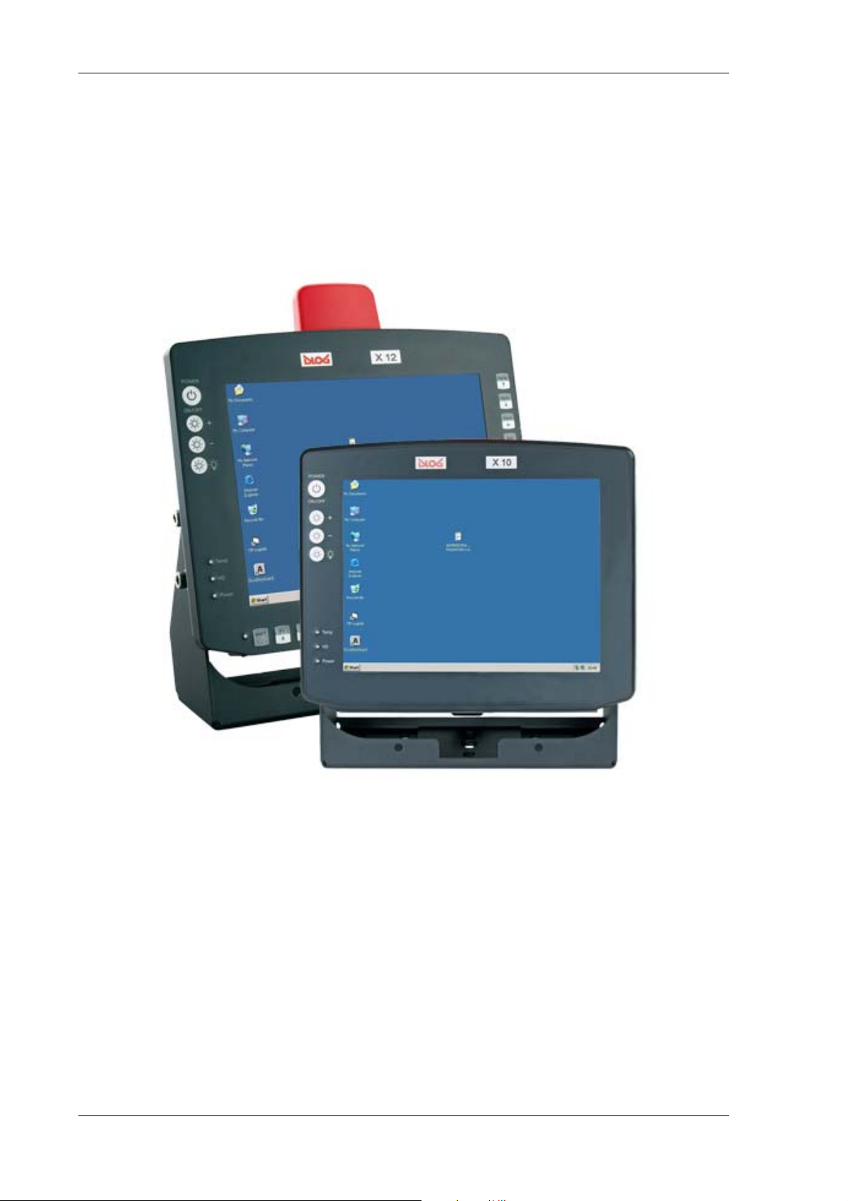
Operation
8.3. Operating controls DLoG X 10 and DLoG X 12
There are a number of indicator lamps and controls on the front of the DLoG X 10 and
DLoG X 12. The standard model has only four buttons and three indicator lamps on the
left-hand side (picture in the foreground). The expanded configuration of the device has
25 buttons (optional, picture in the background).
Figure 8.3: Operating controls DLoG X 10 and X 12
Note for all units featuring a brightness control: Even after manually turning off the
backlighting, the DLoG X device will continue to respond to interaction via the keyboard,
mouse or touch screen. This means that you can continue to enter commands and data
even if the display lighting is off.
70 Manual DLoG X Series
Page 83

Operation
8.3.1. Front controls (standard)
Indicator/control Explanation
<Power> button to switch the DLoG X 10 / 12 on/off:
This button has been preconfigured by DLoG to provide the
following functions by default:
DLoG X 10 / DLoG X 12 with
DC power supply and
automatic switch off:
DLoG X 10 / DLoG X 12 with
DC power supply, without
automatic switch off:
DLoG X 10 / DLoG X 12 with
AC power supply and
automatic switch off:
DLoG X 10 / DLoG X 12 with
AC power supply, without
automatic switch off:
<Power> button is not used for powering
up the unit. If the button is pressed before
the shutdown delay time has elapsed, the
unit is powered down immediately.
<Power> button is used to power up the
unit. If the button is pressed while the unit is
operating, this results in a HARD shutdown.
This may lead to data loss!
<Power> button is used to power up the
unit. If the button is pressed while the unit is
in operation, all applications are quit and
the DLoG X is properly shut down.
<Power> button is used to power up the
unit. If the button is pressed while the unit is
operating, this results in a HARD shutdown.
This may lead to data loss!
<+> button for manual brightness control (optional)
<-> button for manual brightness control (optional)
Turning the backlighting ON/OFF
Temp (red LED) indicates an excessively high or low
temperature inside the unit
HD (green) LED – not used
Power (green LED): indicates connection to a power supply
DLoG X Series Manual 71
Page 84
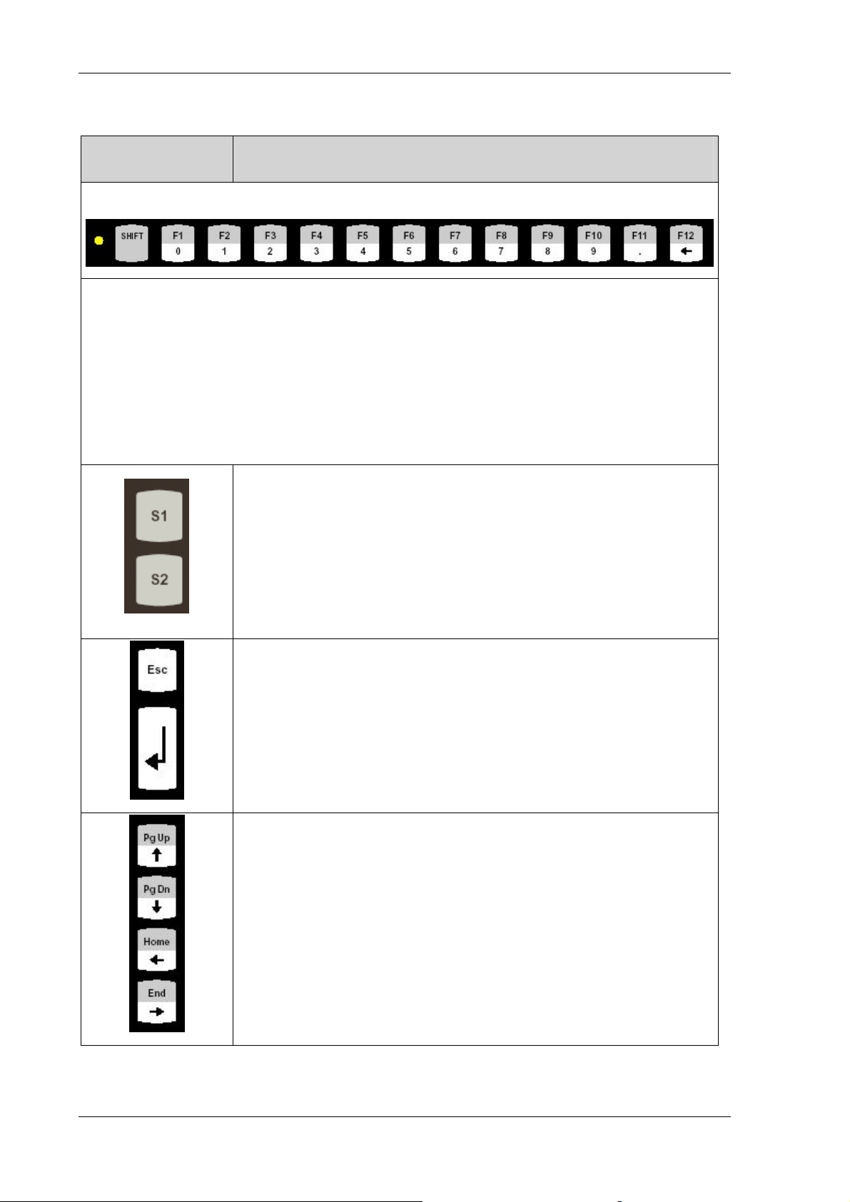
Operation
8.3.2. Front controls (extended)
Indicator/control Explanation
yellow LED: indicates the status of the <Shift> key
<0/F1>: digit “0“, or function key <F1> if the <Shift> key is pressed to
<9/F10>: digit “9“, or function key <F10> if the <Shift> key is pressed
<. / F11> decimal point, or function key <F11> if the <Shift> key is pressed
<Í / F12> <Backspace or function key <F12> if the <Shift> key is pressed
<S1> Special key
Pressing this key has the same effect as simultaneously pressing
the <Ctrl> and <+> key on the keypad
<S2> Special key
Pressing this key has the same effect as simultaneously pressing
the <Ctrl> and <-> key on the keypad.
<Esc> key
<Enter> key, also called the <Return> key
Ï/PgUp “Cursor Up” or “Page Up” when pressing the
<Shift> key
Ð/PgDn “Cursor Down” or “PageDown” when pressing the
<Shift> key
Í/Home “Cursor Left” or all the way left on that line when
pressing the <Shift> key
Î/End “Cursor Right” or all the way right on that line when
pressing the <Shift> key
72 Manual DLoG X Series
Page 85
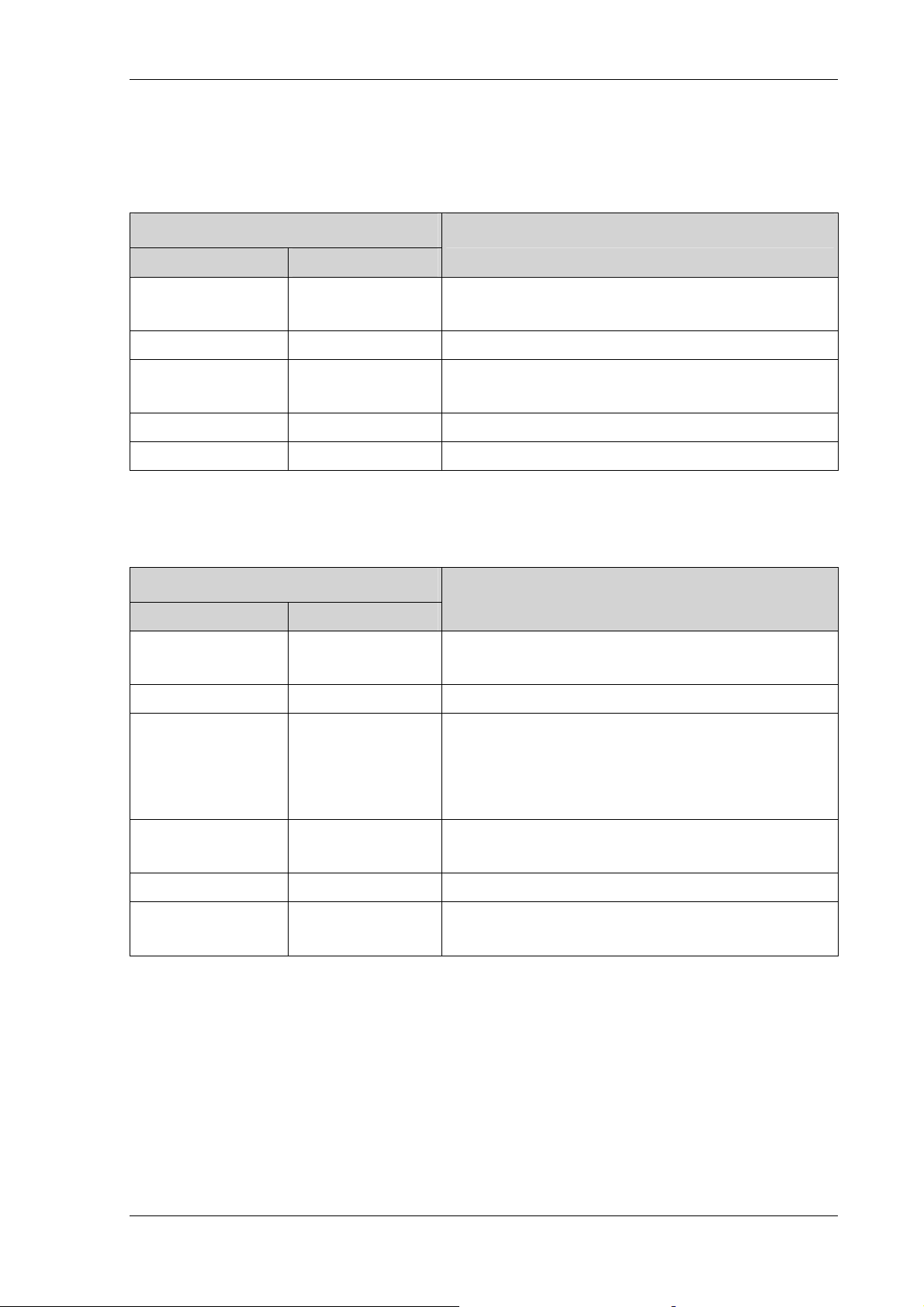
Operation
8.4. LED / Operating states
8.4.1. DLoG X 7
Status of internal LEDs
Power (green) Temp (red)
OFF OFF
OFF FLASHING
ON OFF
ON ON
ON FLASHING
8.4.2. DLoG X 10 and DLoG X 12
Status of internal LEDs
Power (green) Temp (red)
aus aus
Device status
Device off, idle time (waiting for a new startup
signalafter switch-off), no power supply
Temperature sensor is malfunctioning
Computer is starting up; normal operational
state; shutdown delay time is running
Temp. < -30 °C or temp. > 50 °C
Temperature sensor is malfunctioning
Device status
Initial state, idle time (waiting for a new ignition
signal after switch-off), no power supply
aus blinkend
aus an
an aus
an an
an blinkend
Temperature sensor is malfunctioning
Heating ON at temperatures < 0 °C, or Excess
temperature warning Temp. > 62 °C ; Computer
starts only after the temperature in the device
reaches the range between 0 °C and 62 °C.
Computer is starting up; normal operational
state; shutdown delay time is running
Temp. < -5 °C or temp. > 70 °C
Temperature sensor malfunction or configuration
of automatic shutoff
DLoG X Series Manual 73
Page 86

Boot loader
9. Boot loader
The DLoG X bootloader initializes, configures and tests the hardware according to the
settings. The operating system will then load.
The Windows CE 5.0 bootloader used in the DLoG X models is based on EBoot from
Microsoft.
The bootloader and operating system are described in greater detail in the Windows CE
technical manual.
Figure 9.1: Boot loader diagram 1
74 Manual DLoG X Series
Page 87
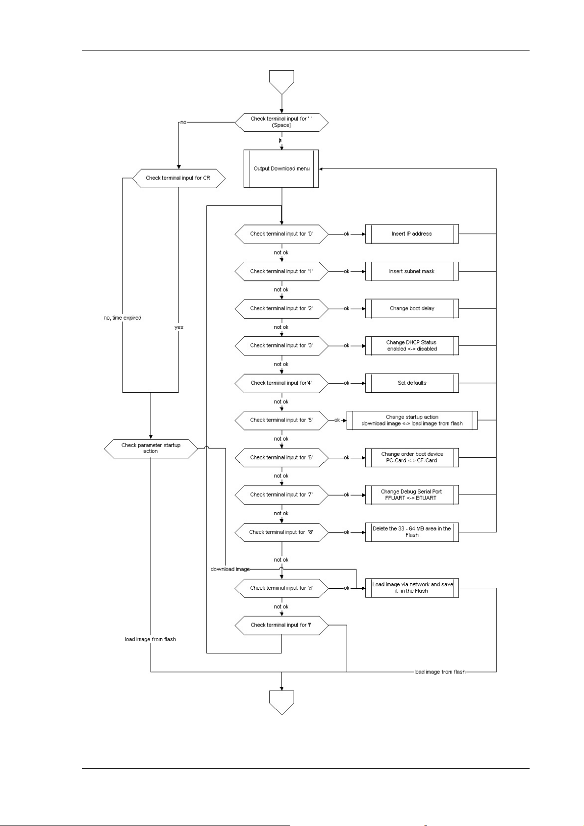
Boot loader
Figure 9.2: Boot loader diagram 2
DLoG X Series Manual 75
Page 88

Operating system
10. Operating system
The DLoG X devices are available with the Windows CE 5.0 or, if requested, Embedded
Linux operating system.
The operating system you order is pre-installed at the factory.
The operating system pre-installed on the DLoG X device is loaded following the
bootloader system messages.
System-specific device drivers – such as those for display, audio, network via PC card,
and touch panels – are also pre-installed.
Refer to the relevant operating system manual for specific operating instructions.
The operating system is integrated into a Flash memory module on the mainboard. Any
memory that is not reserved for the operating system can be used by the user. It is also
possible to add additional memory space through USB, SD cards or CompactFlash.
76 Manual DLoG X Series
Page 89

Software applications
11. Software applications
11.1. Settings with PD.EXE
11.1.1. Configuring backlight, automatic switch off and more
The PD.EXE software is used to adjust important settings for the DLoG X models with
Windows CE such as backlighting, automatic switch off and in some cases the front
keyboard assignment.
Please note that you can only implement these settings if you have purchased the
respective option.
11.1.2. PD.EXE dialogs horizontally or vertically
PD.EXE dialogs are either displayed horizontally or vertically depending on which display
setting you have selected on the DLoG X device.
11.1.3. Save PD.EXE settings
To save the PD.EXE settings, it is enough to exit the corresponding program dialog using
OK. It is NOT necessary to execute the saveregistry command.
11.1.4. Launch PD.EXE
Due to the special interaction between the hardware and software, the PD.EXE software
can be only launched simultaneously once. A subsequent launch will result in an error.
First check that no check symbol is displayed in the task bar. If the symbol is shown, this
indicates that the program is already running.
Figure 11.1: Symbol for launched PD.EXE in the task bar
DLoG X Series Manual 77
Page 90

Software applications
11.1.4.1. Automatical start
The DLoG X device is generally configured at the factory so that the PD software
launches automatically when starting up the computer.
Programs to be automatically started are found under Windows | Startup.
11.1.4.2. Manual start
A manual start may be required if the PD program has been closed by clicking on the
Advanced | Exit menu option.
If this menu option is deactivated, it may be possible that you do not have the necessary
permission to quit the program. Further information on this topic can be found under
Advanced | Set User Permissions.
Clicking the “x” at the top right of the window does not close the program, but simply
minimizes the software window.
To ensure that a manual start works:
• You need to show the hidden files and ‘My Device -> Windows -> StartUp’ folders.
• You need to show the protected operating system files.
If these folders are not
shown on your DLoG X device:
1. Click View followed by Options from the menu bar.
2. Deselect the checkboxes: Do not show hidden files and folders and Hide
protected operating system files.
3. Click OK. The Windows folder is now displayed
4. Select the StartUp folder.
5. You can double-click the DLoG PD symbol to launch the software.
78 Manual DLoG X Series
Page 91

Software applications
11.1.4.3. Startup screen
When launching the PD software the system displays an initialization screen. This screen
is displayed irrespective of the start-up method used.
The system carries out three tests before activating the software.
• Open COM port
• Create communication link with environment controller
• Load setup
If the program has been successfully started, a check symbol will appear in the task bar.
If one of the tests fails, the software will not launch. Should this occur, please consult
DLoG support.
If you try to launch the software a second time, an error will occur and the second
instance will terminate in error.
• Click the check symbol to open the program.
11.1.5. Menu bar
If some of the options in the menu bar are grayed out, then you may not have the
necessary permission to modify these settings. Further information can be found in
chapter Advanced | Set User Permissions.
DLoG X Series Manual 79
Page 92
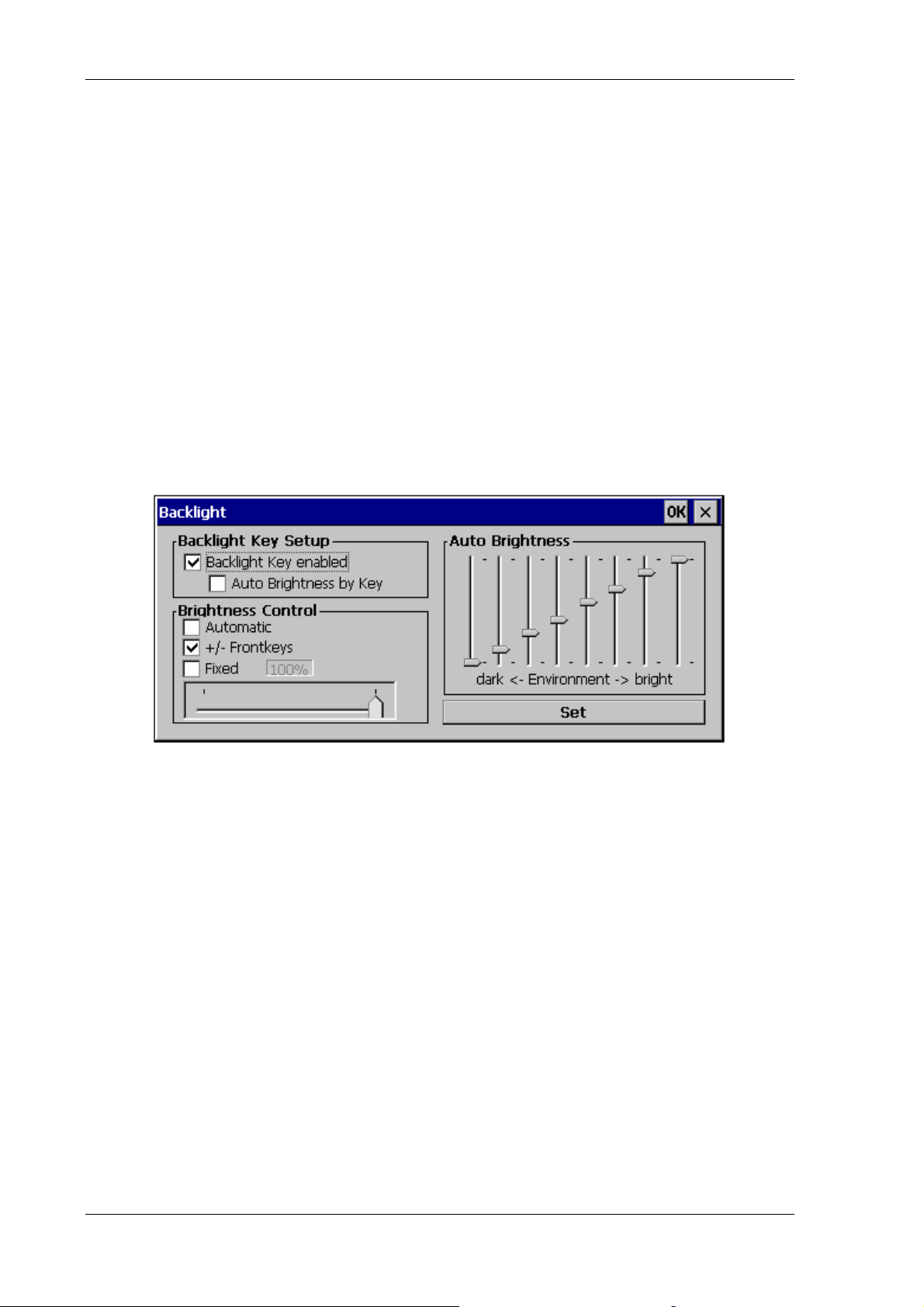
Software applications
11.1.6. Options menu The Options menu contains the following functions:
• Backlight
• Set Front Keys
• Switch Off
• USB-Port Config
• Remote Control
11.1.6.1. Backlight
Clicking the Backlight function will result in the following dialog box:
Figure 11.2: Setup dialog box for backlight
80 Manual DLoG X Series
Page 93

Software applications
Configuring the backlight key setup:
Backlight Key
enabled
Auto Brightness
by key
Enables or disables the backlight key on the front of the
device.
Please note: Auto brightness control is only available on
the DLoG X 7 device!
Press and hold the backlight key for approx. 3 seconds to
toggle between automatic and manual brightness control.
You can set the brightness manually using +/- Front keys
or Fixed. Both the automatic and the manual controls must
be selected. If you select only one method of control, you
will not be able to toggle between the two control modes.
Configuring the brightness control:
You can only select one
mode for brightness control.
Exception: In order to toggle between the two control modes from the device front, the
Auto Brightness by Key option must be activated. This offers two modes for selection.
Further information can be found under the section on Backlight Key Setup above.
+/- Front keys Enables or disables the keys + and - on the front of the
device
Fixed Configures a fixed brightness for the display. Use the
slide control to set the desired brightness.
Automatic Please note: The brightness sensor is only available on
the DLoG X 7 device!
This function enables the brightness sensor on the front
of the device. Use the slide control to set the desired
brightness curve for the display.
Set Saves and activates your settings. You can also save
the settings by clicking OK. This button allows you to
test the various settings without having to close the
dialog window.
DLoG X Series Manual 81
Page 94

Software applications
11.1.6.2. Set Front Keys
Using Set Front Keys you can assign the front keys on the DLoG X with particular
commands or with program activation. When the function opens up, an interactive
graphic appears with all available keys on the DLoG X device.
• In the graphic, touch one of the front panel keys to configure it.
Parameters:
Switch front Shift ON Activate or deactivate the <Shift> key
Editor line This displays the code that is automatically generated
with configuring a key. If, for example, the key “0” is
selected from the list (like in the illustration), the code K\0
is displayed.
This line can also be edited by hand.
Clear key Delete an existing entry (for the colored key indicated in
the list of options). The accompanying code can be seen
in the editor line in the upper part of the dialog. At the
end of the process, this editor line is empty.
Save key Save the configuration just made.
Add key Transfer a key from the list to the editor line.
List of available
Selection list of all available keys
functions
Key up / key down Check off whether the desired key should be simulated
with “press and release” action. One example of a case
where only pressing (down) is desired is with the <Shift>
key, which is usually pressed together with another key.
Start program by key Data entry line for starting a program
Add program Enter a program on the editor line
82 Manual DLoG X Series
Page 95

Software applications
Virtual key codes
Action keys can also be programmed with Windows virtual key codes. The virtual key
codes are entered on the editor line and stored with the Save Key.
Virtual key code names can be obtained, for example, from the Microsoft MSDN website
(Microsoft Developer Network).
11.1.6.3. Automatic switch off
This option allows you to configure the automatic switch off for DLoG X devices.
Figure 11.3: Automatic switch off Dialog PD.EXE
Automatic switch off
You can only implement this setting if you have purchased the automatic switch off
option.
DLoG X Series Manual 83
Page 96

Software applications
The parameters for this dialog box are:
Enable
Enables or disables the automatic switch off
Switch off Automatic
Lock Screen Disables input from the keyboard or touch screen for
the specified delay time
Show countdown Displays the countdown screen until the system powers
down.
Shutdown Button Displays the off button on the countdown screen.
Delay Time Time between switching off the ignition and starting
shutdown. If the ignition signal is restarted, the system
will return to standard operation
Switch off Time until the applications have been shut down. This
Power Key Functions
Power Key enabled Enables or disables the power key on the front of the
time interval starts at the end of the delay time or once
the power key on the front of the device has been
pressed
device If the key is disabled, you cannot use it to switch
the power supply on or off.
84 Manual DLoG X Series
Page 97

Software applications
Power on
Proceed carefully with these settings! These definitions determine which action starts the
DLoG X terminal.
Do NOT select Ignition if an ignition cable has not been connected.
If you select Ignition and an ignition cable has not been connected,
the DLoG X terminal will no longer start.
Do NOT select Power key or Ignition or Power key + Ignition if
an ignition cable has not been connected. If you select one of these
settings and an ignition cable has not been connected, the DLoG X
terminal will no longer start.
Always On The DLoG X switches on as soon as it is supplied with
power. It is not necessary to press the <Power> key or start
the ignition.
Ignition The computer switches on automatically when the ignition is
started. It cannot be switched on with the <Power> key.
Power key The computer can be switched on with the <Power> key.
If the <Power> key is disabled, you cannot select any
options for the <Power> key.
Power key or
Ignition
Power key +
Ignition
The computer can be switched on with the ignition signal or
the <Power> key.
The computer can be switched on with the <Power> key if
the ignition is on. It cannot be switched on with the <Power>
key alone.
If the <Power> key is disabled, you cannot select any
options for the <Power> key.
DLoG X Series Manual 85
Page 98

Software applications
Power off
Proceed carefully with these settings! These definitions determine which action switches
off the DLoG X terminal.
Do NOT select Ignition if an ignition cable has not been connected.
If you select Ignition and an ignition cable has not been connected,
the DLoG X terminal will shut down after the delay time expires.
Do NOT select Power key or Ignition or Power key + Ignition if
an ignition cable has not been connected. If you select Power key
or Ignition or Power key + Ignition and an ignition cable has not
been connected, the DLoG X terminal will shut down after the delay
time expires.
Always On The DLoG X switches off as soon as it is no longer supplied
with power.
Ignition Switching off the ignition activates the automatic switch off
function.
Power key The computer is shut down or switched off with the
<Power> key (if no automatic switch off is available, a hard
shutdown takes place).
Power key or
Ignition
Ignition + Power
key
The computer can be switched off with the ignition signal or
the <Power> key.
Automatic switch off is activated when the ignition is
switched off. The <Power> key shortens the defined delay
time and initiates computer shutdown.
86 Manual DLoG X Series
Page 99
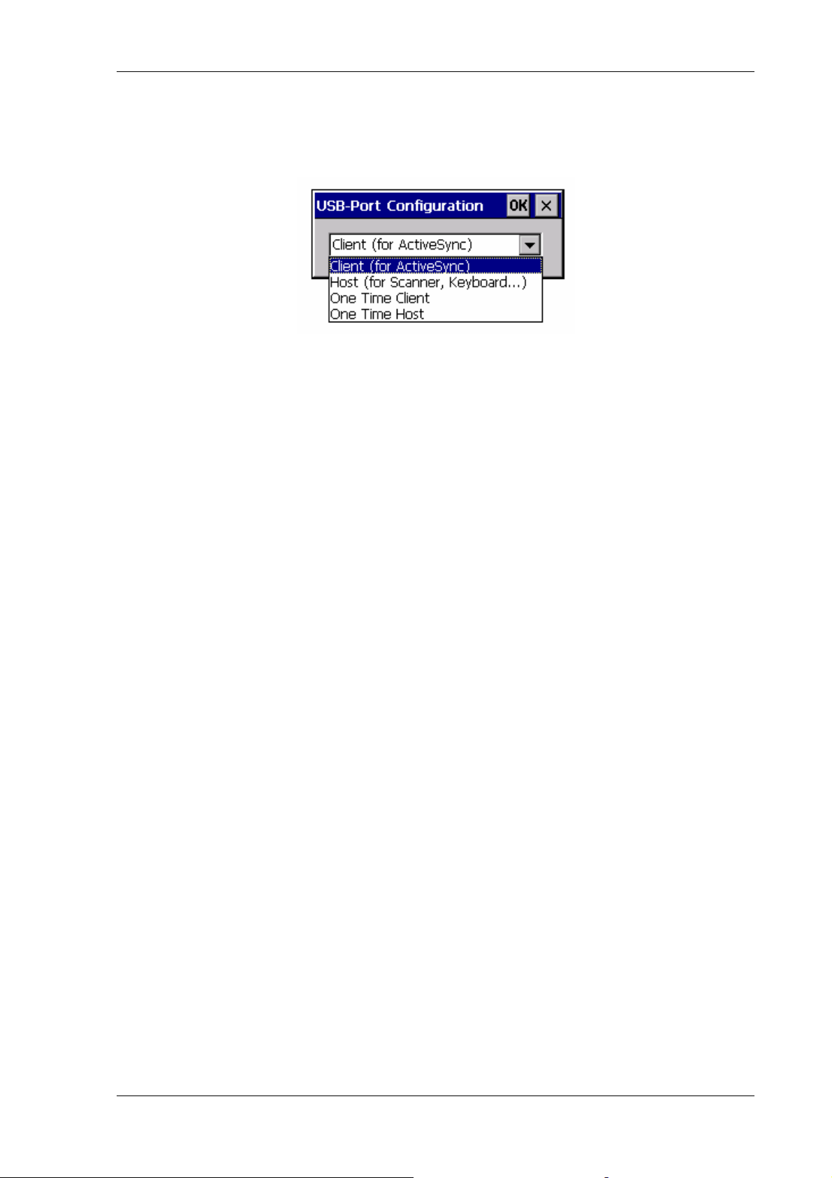
Software applications
11.1.6.4. USB-Port Config
This menu allows you to configure the USB interfaces.
Figure 11.4: USB-Port Configuration in PD.EXE
Client (for ActiveSync)) The USB client is active; the USB host port is
inactive.
Host
(for scanner, keyboard, …)
The USB host is active; the USB client port is
inactive.
One Time Client The USB client is non-recurring and is only
active until the next computer start. Then the
USB host automatically becomes active again.
One Time Host The USB host is non-recurring and is only
active until the next computer start. Then the
USB client automatically becomes active
again.
11.1.6.5. Remote Control
This function was not yet been implemented upon publication of the manual.
DLoG X Series Manual 87
Page 100

Software applications
11.1.7. Advanced menu The Advanced menu offers the following functions:
• Change Running Mode
• Change EE-Data
• Upgrade
• PIC-Update
• Set User Permissions
• Production Set
• Exit
11.1.7.1. Change Running Mode
The Change Running Mode menu option allows you to modify the running mode of the
PD program. The system offers three permission levels: User, Admin (administrator)
and Service.
The program launches in the User mode by default. This is indicated by the black check
symbol in the task bar. You can modify the user permissions in the Administrator or
Service mode. The Service password is intended for DLoG support only.
Enter Password
Admin You must enter the Administrator password here .
The default password for the Administrator mode is ‘gold’.
DLoG You must enter the Service password here.
The service password is intended for DLoG support only.
• Click Enter to confirm.
The color of the check symbol will then change to yellow.
The process can be terminated for security reasons by pressing the enter key on the
keyboard. The existing run mode remains unchanged.
88 Manual DLoG X Series
 Loading...