

Page 1
DLoG MPC 6
Manual
1.01
Page 2

This manual contains a detailed description of the product and we have made every
effort to make it as accurate as possible. However, this is not a guarantee of the features
or the functionality of the product.
We reserve the right to modify the contents of this document at any time and without
prior notice.
Because we at DLoG are constantly striving to improve this product, we cannot
guarantee that previous or subsequent releases of the product will correspond in every
respect with the product description given in this manual.
DLoG GmbH assumes no liability for technical inaccuracies, typographic errors or faults
in this documentation. DLoG GmbH also assumes no liability for damages caused
directly or indirectly by the delivery, performance or usage of this material.
The software and hardware designations used in this documentation are in most cases
also registered trademarks and are thus subject to law.
Windows® is a registered trademark of Microsoft Corporation in the United States (US)
and other countries.
This documentation is protected by copyright. Duplication, in whole or in part, is not
permitted without prior written approval of DLoG GmbH!
Title of documentation: Manual DLoG MPC 6
Documentation completed on: November 16, 2006
Version: V1.01
Product number 885191E
© Copyright 2006
DLoG GmbH
Werner-von-Siemens-Strasse 13
Technical customer support
If you experience technical difficulties,
please consult your distributor or contact
D-82140 Olching, Germany
All rights reserved
the technical services department at
DLoG’s headquarters:
(+49) 8142/2860-0
Page 3
Page 4

Page 5

Table of contents
1. About this manual..................................................................................1
1.1. Device version described...........................................................................................1
1.2. For qualified personnel ..............................................................................................1
1.3. Design method...........................................................................................................2
1.3.1. Warnings and notices ........................................................................................2
1.3.2. Additional design elements................................................................................2
2. Important safety notices........................................................................4
2.1. Initial operation of the device.....................................................................................4
2.2. Power supply/external peripheral devices .................................................................6
2.3. Repairs only through DLoG .......................................................................................7
2.4. Opening and closing the device.................................................................................8
2.5. Exchanging and extending modules........................................................................10
2.6. CE Marking ..............................................................................................................12
2.7. RTTE Directive 1999/5/EC ......................................................................................12
2.7.1. Special regulations in France ..........................................................................12
2.8. FCC user information...............................................................................................13
2.8.1. Interference declaration of the Federal Communications Commission...........13
2.8.2. Transmission of radio frequencies...................................................................14
3. Device description................................................................................15
3.1. General ....................................................................................................................15
3.2. Intended usage ........................................................................................................16
3.3. The models: DLoG MPC 6/110 and DLoG MPC 6/112...........................................16
3.4. Abbreviations used for devices and accessories.....................................................16
3.5. Device description and type identification ...............................................................17
3.5.1. Device type plate .............................................................................................17
3.6. Technical specifications...........................................................................................19
3.6.1. Mechanical.......................................................................................................19
3.6.2. Motherboard ....................................................................................................20
Page 6

3.6.3. LCD/CRT interface..........................................................................................22
3.6.4. Touch screen (optional)................................................................................... 22
3.6.5. Network interface ............................................................................................23
3.6.6. ADC/MDC interface (optional)......................................................................... 23
3.6.7. Cardbus interface (optional)............................................................................ 23
3.6.8. PCI Express® MiniCard interface for WLAN (optional)................................... 24
3.6.9. Power supply................................................................................................... 25
3.6.10. Maximum power available for peripheral devices.......................................26
3.6.11. Power supply fuses ..................................................................................... 27
3.6.12. Ambient conditions...................................................................................... 28
3.6.13. Test marks................................................................................................... 29
3.6.14. Dimensions.................................................................................................. 30
3.6.15. VESA drill holes........................................................................................... 36
4. Unpacking the DLoG MPC 6................................................................37
4.1. Scope of delivery.....................................................................................................37
4.2. Packaging................................................................................................................ 37
4.3. Returning your device.............................................................................................. 37
5. Putting your DLoG MPC 6 in operation..............................................38
5.1. Cooling through the supply of fresh air.................................................................... 38
5.2. Pin configuration...................................................................................................... 39
5.3. External connectors................................................................................................. 39
5.3.1. AC voltage supply connector........................................................................... 41
5.3.2. DC voltage supply connector ..........................................................................41
5.4. Connecting external devices ................................................................................... 43
5.4.1. Powering down the DLoG MPC 6 ...................................................................44
5.5. WLAN settings......................................................................................................... 45
5.5.1. Radio performance.......................................................................................... 45
5.5.2. DLoG antenna solutions for use in Germany.................................................. 46
5.6. Removing the protective film from the display ....................................................... 46
5.7. Powering up the DLoG MPC 6 ................................................................................47
5.8. Protecting the TFT display from the memory effect ................................................ 47
Page 7

6. Accessories ..........................................................................................48
6.1. Keyboard..................................................................................................................48
6.1.1. SMALL keyboard .............................................................................................48
6.1.2. 24-key keypad .................................................................................................49
6.2. Mouse ......................................................................................................................50
6.3. External CD-ROM drive ...........................................................................................51
6.4. External floppy disk drive.........................................................................................52
6.5. USB stick .................................................................................................................53
6.6. Scanners..................................................................................................................53
6.7. WLAN cards (PC card, cardbus, PCIe minicard).....................................................53
7. Installation.............................................................................................54
7.1. Options for installing the device...............................................................................54
7.2. Permitted mounting positions ..................................................................................55
7.3. Follow and retain the installation instructions..........................................................56
7.4. Mechanical dynamic loading....................................................................................56
7.5. Power supply ...........................................................................................................57
7.5.1. AC power pack ................................................................................................57
7.5.2. DC power pack ................................................................................................58
7.5.3. Installing connecting cables.............................................................................59
7.6. Vehicle applications (such as forklifts).....................................................................59
7.7. Cable cover (splash guard)......................................................................................61
7.7.1. Protection class IP65.......................................................................................61
7.7.2. Protection class IP54.......................................................................................62
8. Operation...............................................................................................64
8.1. 4 key front panel ......................................................................................................64
8.2. 10 key front panel ....................................................................................................65
8.3. 25 key front panel ....................................................................................................66
8.3.1. Power key ........................................................................................................67
8.3.2. Manual brightness control/backlighting ...........................................................68
8.3.3. LEDs ................................................................................................................68
8.3.4. Function and number keys ..............................................................................69
Page 8

8.3.5. Special keys ....................................................................................................69
8.3.6. Escape key, enter key and scroll keys............................................................70
8.4. Operating states ...................................................................................................... 71
9. Operating system.................................................................................72
9.1. Pre-installed on the hard drive/Compact Flash ....................................................... 72
9.2. Installing on the hard drive/Compact Flash............................................................. 73
9.2.1. Operating systems supplied on CD-ROM....................................................... 73
9.2.2. Operating system images................................................................................ 74
9.2.3. Operating systems on floppy disk ................................................................... 74
9.3. Special features of the operating systems ..............................................................75
9.3.1. MS-DOS .......................................................................................................... 75
9.3.2. Windows XP Embedded.................................................................................. 75
9.3.3. Linux................................................................................................................ 75
10. Software applications......................................................................76
10.1. Displaying the configuration of the DLoG MPC 6................................................ 76
10.2. Fine tuning the operating system parameters..................................................... 76
10.3. Environment controller settings........................................................................... 77
11. Serial ports........................................................................................79
11.1. Resources ...........................................................................................................79
11.2. COM1 options...................................................................................................... 79
11.3. COM1 as a power supply....................................................................................79
11.4. COM2 options...................................................................................................... 80
11.5. COM2 as electrically-isolated RS-422/485 .........................................................80
11.6. Drivers ................................................................................................................. 81
11.6.1. RS-232 operation ........................................................................................ 81
11.6.2. RS-4xx operation......................................................................................... 81
11.7. Serial port printers ............................................................................................... 81
11.8. Serial port barcode scanners ..............................................................................82
11.8.1. Tips & tricks................................................................................................. 83
Page 9

12. Internal devices.................................................................................84
12.1. Chipset.................................................................................................................84
12.1.1. Installing chipset drivers under MS-DOS ....................................................84
12.1.2. Installing chipset drivers under Windows XP ..............................................84
12.2. VGA adapter ........................................................................................................86
12.2.1. VGA driver installation under MS-DOS .......................................................86
12.2.2. VGA driver installation under Windows XP .................................................86
12.3. Network adapter (10/100)....................................................................................88
12.3.1. Network driver installation under MS-DOS..................................................89
12.3.2. Network driver installation under Windows XP............................................89
12.4. Onboard sound adapter.......................................................................................91
12.4.1. Installation of the onboard sound adapter drivers (Win XP)........................91
12.5. Touch screen .......................................................................................................93
12.5.1. MS-DOS installation and calibration for driver version 5.06........................94
12.6. Touch (Serial) for Windows XP Prof. and XP Embedded ...................................96
12.6.1. Installation....................................................................................................96
12.6.2. Calibration....................................................................................................98
12.7. Touch (PS2) for Windows XP Prof. and XP Embedded......................................99
12.7.1. Installation....................................................................................................99
12.7.2. Calibration..................................................................................................100
12.8. Resistance of the touch screen .........................................................................101
12.9. Plug-in cards......................................................................................................103
12.9.1. Riser card with 1x PCI ...............................................................................104
12.9.2. TerraTec 128i PCI sound card ..................................................................104
12.9.3. CAN card ...................................................................................................104
12.10. Automatic switch-off and heating.......................................................................105
12.10.1. Automatic shutdown process.....................................................................106
12.10.2. Program flowchart......................................................................................107
12.10.3. Drivers .......................................................................................................109
12.10.4. General notes about the automatic shutdown software in Windows ........110
Page 10

13. Maintenance....................................................................................111
13.1. Cleaning the housing......................................................................................... 111
13.2. Touch screen cleaning ...................................................................................... 111
14. Common mistakes in usage..........................................................112
14.1. Power supply..................................................................................................... 112
14.2. Powering up/down............................................................................................. 112
14.3. Cable cover .......................................................................................................112
14.4. Installation .........................................................................................................113
14.5. Mobile application on vehicles........................................................................... 113
14.6. Using the touch screen...................................................................................... 114
14.7. Use/storage in extreme temperatures............................................................... 114
15. Disposal ..........................................................................................115
16. Appendix A: System resources ....................................................116
16.1. Part 1 .................................................................................................................116
16.2. Part 2 .................................................................................................................118
17. Appendix B: Terminal assignment (Pins) ....................................119
17.1. External connectors........................................................................................... 119
17.1.1. Keyboard and Mouse ................................................................................119
17.1.2. USB ........................................................................................................... 120
17.1.3. Serial port COM1....................................................................................... 120
17.1.4. Serial port COM2....................................................................................... 121
17.1.5. Network connector ....................................................................................122
17.2. Internal connectors, motherboard MPC6.20 ..................................................... 123
17.2.1. Cardbus connector.................................................................................... 124
17.2.2. Input voltage connector............................................................................. 126
17.2.3. Ignition signal connector ...........................................................................126
17.2.4. Heating power connectors ........................................................................127
17.2.5. Serial port COM2....................................................................................... 127
17.2.6. Audio port ..................................................................................................128
17.2.7. IDE connector............................................................................................ 129
Page 11

17.2.8. Compact Flash connector..........................................................................130
17.2.9. LCD connector...........................................................................................131
17.2.10. Front keyboard connector..........................................................................132
17.2.11. Inverter connector......................................................................................132
17.2.12. Touch connector........................................................................................133
17.2.13. Riser card connector .................................................................................134
17.2.14. Internal connectors, riser card...................................................................135
17.2.15. PCI connector............................................................................................136
17.2.16. VGA Interface (for service purposes only) ................................................139
17.2.17. COM4 connection......................................................................................140
17.2.18. USB post 3 and 4 ......................................................................................141
17.2.19. PCIe MiniCard socket................................................................................142
18. Appendix C: Jumper.......................................................................143
18.1. Warnings............................................................................................................143
18.2. Standard jumper settings...................................................................................143
18.3. Jumper layout view, motherboard .....................................................................144
18.3.1. Battery .......................................................................................................145
18.3.2. Ethernet configuration ...............................................................................145
18.3.3. Compact Flash configuration.....................................................................145
18.3.4. Touch enable.............................................................................................146
18.3.5. Touch configuration ...................................................................................146
18.3.6. COM1 configuration...................................................................................147
18.3.7. LCD configuration......................................................................................147
18.3.8. Compact Flash DMA configuration............................................................148
18.3.9. Touch interface selection...........................................................................148
18.3.10. External shield connection.........................................................................148
19. Appendix D: Tools..........................................................................149
19.1. Please follow the safety notices ........................................................................149
19.2. DLoG MPC 6 toolkit...........................................................................................150
19.3. Mounting bracket toolkit.....................................................................................151
Page 12

20. Appendix E: Mechanical dynamic loading...................................152
20.1. Introduction........................................................................................................ 152
20.2. Using the device without vibration insulation (tuned to a high frequency)........154
20.3. Use with passive vibration insulation (tuned to a low frequency)...................... 155
20.4. Dimensioning example DLoG MPC 6/110 ........................................................156
20.4.1. Approximate solution for the selection of elastomer springs ....................158
20.4.2. Further possible steps for optimization: ....................................................160
20.4.3. Approximate solution for determining insulating effects............................ 161
20.5. Determining natural frequencies .......................................................................163
21. Appendix F: BIOS...........................................................................164
21.1. BIOS setup description...................................................................................... 164
21.2. Entering the BIOS setup program .....................................................................164
21.3. Setup menu and navigation............................................................................... 165
21.4. Main setup screen ............................................................................................. 166
21.5. Advanced setup................................................................................................. 168
21.5.1. ACPI configuration submenu ....................................................................169
21.5.2. PCI configuration submenu....................................................................... 170
21.5.3. Graphics configuration submenu ..............................................................172
21.5.4. CPU configuration submenu ..................................................................... 174
21.5.5. Chipset configuration submenu................................................................. 174
21.5.6. I/O Interface configuration submenu......................................................... 175
21.5.7. IDE configuration submenu....................................................................... 176
21.5.8. USB configuration submenu .....................................................................180
21.5.9. Keyboard/mouse configuration submenu .................................................182
21.5.10. Remote access configuration submenu.................................................... 183
21.5.11. Hardware monitoring submenu .................................................................185
21.5.12. Watchdog configuration submenu............................................................. 186
21.6. Boot setup .........................................................................................................188
21.6.1. Boot device priority.................................................................................... 189
21.6.2. Boot settings configuration........................................................................ 190
21.7. Security setup.................................................................................................... 191
21.7.1. Security Settings .......................................................................................192
21.7.2. Hard disk security...................................................................................... 193
Page 13

21.8. Exit menu...........................................................................................................194
21.9. Additional BIOS features ...................................................................................195
21.9.1. Updating the BIOS.....................................................................................195
21.10. BIOS recovery....................................................................................................543H199
246H21.11. BIOS security features.......................................................................................544H199
247H21.12. Hard disk security features ................................................................................545H200
248H22. Return packing slip........................................................................546H201
249HIndex............................................................................................................547H202
Page 14

List of figures
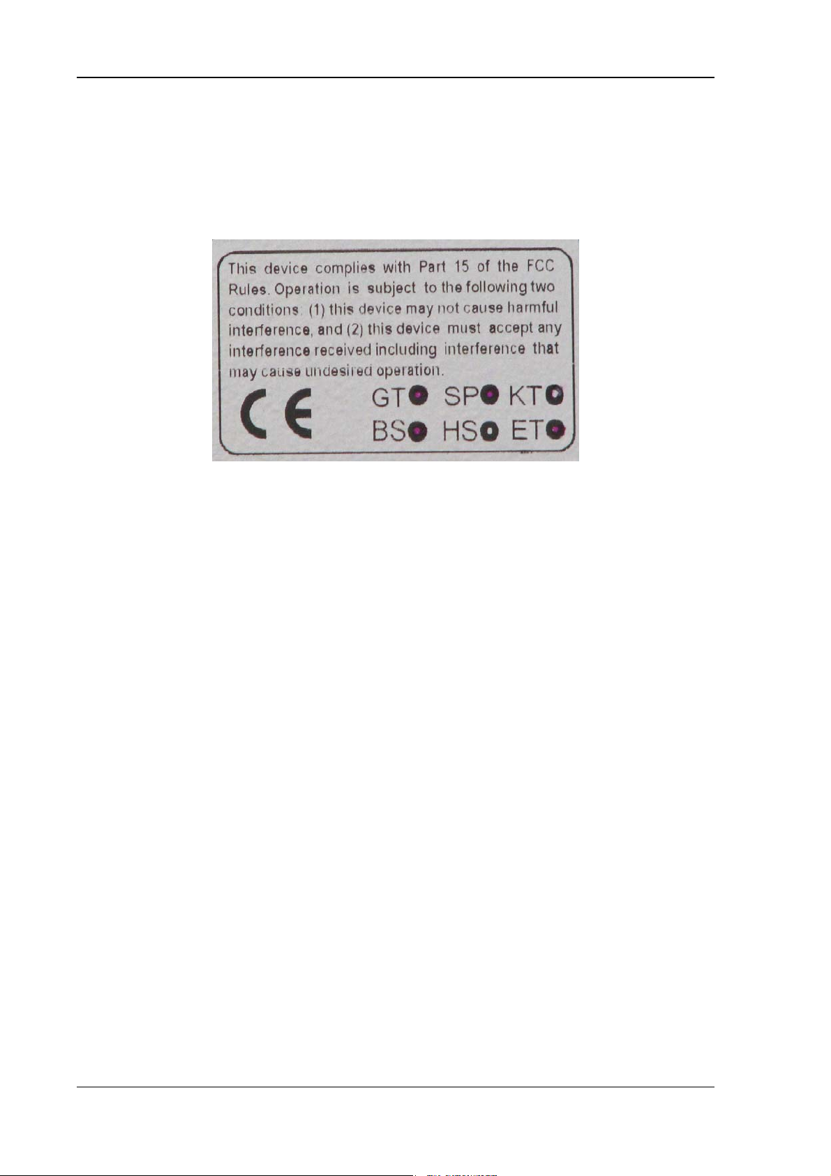
Figure 2.1: CE Marking.....................................................................................................12
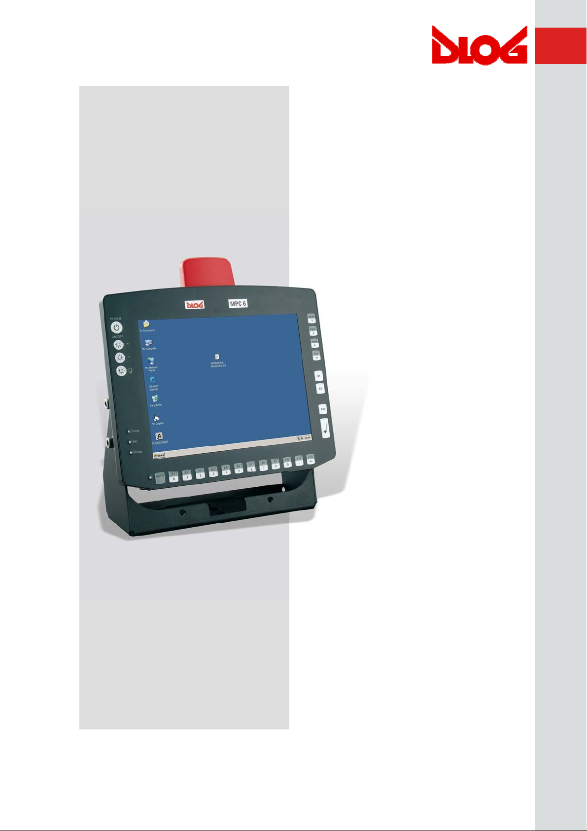
Figure 3.1: DLoG MPC 6 with optional mount..................................................................15
Figure 3.2: Example of a device type plate ...................................................................... 18
Figure 3.3: DLoG MPC 6/110 SVGA front view ...............................................................30
Figure 3.4: DLoG MPC 6/110 SVGA side view ................................................................31
Figure 3.5: DLoG MPC 6/110 SVGA top view.................................................................. 32
Figure 3.6: DLoG MPC 6/112 front view ..........................................................................33
Figure 3.7: DLoG MPC 6/112 side view ...........................................................................34
Figure 3.8: DLoG MPC 6/112 top view............................................................................. 35
Figure 3.9: DLoG MPC 6/110 with VESA drill holes.........................................................36
Figure 5.1: External connectors, AC version....................................................................39
Figure 5.2: External connectors, 24/48 VDC 60 W version..............................................39
Figure 5.3: External connectors, 24/48 VDC 100 W version............................................40
Figure 5.4: External connectors, 12 VDC 100 W version.................................................40
Figure 5.5: Exterior view of the AC power supply connector............................................41
Figure 5.6: Exterior view of the DC power supply connector ...........................................41
Figure 5.7: Cable diagrams of the DC device’s supply connection..................................42
Figure 6.1: SMALL keyboard on the DLoG MPC 6 ..........................................................48
Figure 6.2: 24-key keypad on the DLoG MPC 6 ..............................................................49
Figure 7.1: Permitted mounting positions of the DLoG MPC 6 ........................................55
Figure 7.2: Position of the ground bolt .............................................................................60
Figure 7.3: DLoG MPC 6 with strain relief........................................................................61
Figure 7.4: DLoG MPC 6 without cable cover ..................................................................62
Figure 7.5: DLoG MPC 6 with cable cover mounted ........................................................63
Figure 8.1: DLoG MPC 6 front panel with 4 keys .............................................................64
Figure 8.2: DLoG MPC 6 front panel with 10 keys ...........................................................65
Figure 8.3: DLoG MPC 6 front panel with 25 keys ...........................................................66
Page 15

Figure 12.1: Welcome screen for chipset driver installation.............................................85
Figure 12.2: Welcome screen for the VGA driver installation...........................................87
Figure 12.3: RJ45 network port ........................................................................................88
Figure 12.4: Network driver installation license agreement..............................................89
Figure 12.5: Start screen for network driver installation ...................................................90
Figure 12.6: Welcome screen for the onboard sound adapter drivers .............................91
Figure 12.7: Warning message for the onboard sound adapter drivers ...........................92
Figure 12.8: “Files Needed” touch installation dialog .......................................................97
Figure 12.9: “Setup Message” touch installation dialog ...................................................99
Figure 12.10: Automatic shutdown program flowchart part 1.........................................107
Figure 12.11: Automatic shutdown program flowchart part 2.........................................108
Figure 17.1: Internal connectors, riser card 1 x PCI.......................................................135
Figure 18.1: Jumper layout, motherboard MPC6.20 06.2006 ........................................144
Figure 19.1: DLoG MPC 6 toolkit....................................................................................150
Figure 19.2: Mounting bracket toolkit .............................................................................151
Figure 20.1: Table-top attachment with elastomer springs ............................................157
Figure 21.1: BIOS advanced setup ................................................................................168
Figure 21.2: BIOS security setup....................................................................................191
Figure 21.3: BIOS exit menu ..........................................................................................194
Figure 21.4: BIOS updating under Windows 1 ...............................................................197
Page 16

Page 17

About this manual
1. About this manual
This manual has been designed to make using the DLoG MPC 6 as simple as possible
and provide expert assistance if problems should occur. It contains important information
on using the device safely, properly and efficiently.
Adhering to the manual helps by avoiding dangers, reducing repair costs and breakdown
times and increasing the reliability and lifespan of the DLoG MPC 6.
DLoG GmbH will not assume responsibility for any damage caused by the improper use
of the DLoG MPC 6 and/or in disregard of the instructions in this manual.
Within this manual, DLoG GmbH strives to provide all the information required for using
your DLoG MPC 6. However, because this is a versatile product that can be used in
many different scenarios, we cannot guarantee that the information contained in this
manual will cover every single aspect.
Should you require further information or if you have questions or issues needing
clarification, please contact your nearest DLoG agent or representative.
1.1. Device version described
This manual describes the DLoG MPC 6 with the motherboard version MPC6 20 06
2006.
1.2. For qualified personnel
This manual was written for qualified personnel. The information is intended exclusively
to complement the expertise of qualified personnel , not to replace it.
DLoG MPC 6 Manual 1
Page 18
About this manual
1.3. Design method
1.3.1. Warnings and notices
Warnings and notices in this manual are indicated as follows:
This symbol indicates general information and hints that help you
to understand how to use the product or the manual.
This symbol warns you of any dangers or hazards that could
potentially cause damage to the terminal or system (such as
malfunctions, data loss, equipment damage, etc.).
This symbol indicates hazards that pose a risk to life and limb
(such as contacting the power supply).
You must heed this information!
1.3.2. Additional design elements Lists are indicated with bullet points, for example:
• DC power packs
• AC power packs
Instructions are numbered, for example:
1. Insert a CD.
2. Press <A>.
2 Manual DLoG MPC 6
Page 19

About this manual
Parameter descriptions (e.g., of a dialog)
Ignition off This parameter is used to set,…
Delay time This indicates the delay time.
Switch-off time The switch-off time should be at least…
Key display
Key names are shown in angle brackets: <F1>, <Ctrl>, <Insert>, <Home>, etc.
Menu options, commands, dialog fields
Examples: In the Edit menu you will find the command Paste | Values.
Click OK to finish.
Entries
Any text that needs to be entered is shown in Courier font, for example:
1. Enter the text abcdefg.
Other methods for emphasis
Any other emphasized text elements are highlighted in bold or underlined
.
References to other chapters in the manual are printed in italics.
DLoG MPC 6 Manual 3
Page 20

Important safety notices
2. Important safety notices
The DLoG MPC 6 was designed and built according to modern technology and accepted
safety regulations. However, the operation of the DLoG MPC 6 can endanger personnel
or third parties and cause damage to the device and other material assets when for
example the device is
• operated by untrained or uninformed personnel.
• not operated correctly.
• operated and maintained incorrectly.
The operator commitments in regards to safety (accident prevention regulations, work
protection) are to be followed.
2.1. Initial operation of the device
Area of application
The device is not designed for use in life-support systems or critical safety systems
where system malfunction can lead to the direct or indirect endangerment of human
life. The operator shall take full responsibility for using the device in these situations.
The device cannot be used in combination with safety functions for machines and
equipment which have to conform to the requirements of EN 954-1.
Choice of location
The ambient conditions at the point of installation must comply with the device’s
protection class.
4 Manual DLoG MPC 6
Page 21

Important safety notices
Installation/initial operation
The device is not supplied with a disconnector (switch) that can be accessed
externally. The power supply connector is therefore used as a disconnector. Therefore
it needs to be easily accessible. If it is necessary to establish a fixed connection, an
easily accessible disconnecting device (e.g. a switch such as a circuit breaker) should
be installed close to the device. Ensure that the power cable is laid so that it is
mechanically protected.
The power supply cables must be laid in accordance with the applicable local
installation regulations.
Radio performance
Do not exceed the maximum permissible transmitting power which is specified by
each separate country. DLoG MPC 6 users must verify this themselves.
Risk of injury
The unit could fall during transit or installation and cause injury. Always ensure that
there are two persons available when installing or removing the device.
Supply of fresh air
The DLoG MPC 6 is based on a passive cooling concept. As a result, the waste heat
which is produced inside the device is emitted over the surface of the housing. For this
system to function properly, sufficient fresh air circulation is required. Never install the
system in a closed environment where the cooling air is unable to dissipate
accumulated heat to the outside.
If the DLoG MPC 6 is not able to draw in fresh cooling air, this may cause overheating
and severe damage to the unit.
The maximum allowed ambient temperature for the system needs to be taken into
account for the concrete application area.
DLoG MPC 6 Manual 5
Page 22

Important safety notices
2.2. Power supply/external peripheral devices
Operation in an emergency
In case of emergency (such as damage to the power cable , or housing, or ingress of
liquid or other foreign bodies), the device must be disconnected immediately from the
power supply. Contact technical support staff at once.
Protection of the power supplies
If, after replacement, the fuse fed by the internal power supply blows again, the
device must be sent in for servicing immediately (see section 3.6.11).
Danger of electrocution when cleaning/servicing the device
In order to avoid electrocution always disconnect the DLoG MPC 6 from the power
supply before cleaning or servicing the device.
When charging the car battery please note
While charging the car battery the DLoG MPC 6 has to be either disconnected from
the battery or it has to be determined that the maximum allowed input voltage of the
DLoG MPC 6 is not exceeded. (see sections 3.6.9 and 7.5).
Wiring
Do not use the DLoG MPC 6 when a cable or plug is damaged. Have the damaged
parts replaced immediately!
Do not connect or disconnect any cables during storms
Data cables must never be connected or disconnected during an electrical storm.
6 Manual DLoG MPC 6
Page 23

Important safety notices
External peripheral devices
The use of additional wiring and other peripheral devices, which are not recommended
or sold by the manufacturer can result in fire, electrocution or personal injury.
If a power supply is used, only use the power supply recommended by the
manufacturer.
Before connecting or disconnecting peripheral devices (exception: USB devices), the
DLoG MPC 6 must be disconnected from the power supply! Otherwise, this could
seriously damage both the DLoG MPC 6 and the connected devices!
Make sure that external peripheral devices with their own power supply are switched
on at the same time or after you start the DLoG MPC 6.
If this is not possible, please ensure that the DLoG MPC 6 is adequately protected
from power leakage caused by an external device.
2.3. Repairs only through DLoG
As a rule, never carry out repairs on the device yourself. Always contact DLoG’s
technical support and send in your unit for repair if necessary.
On the back of the DLoG MPC 6 you will find the device’s type plate which has
important information about the device which you must quote for technical service. It
provides important information about the configuration and manufacture of the device
in abbreviated form.
Always provide technicians with the full model name and serial number.
DLoG MPC 6 Manual 7
Page 24

Important safety notices
2.4. Opening and closing the device
If you choose to open the DLoG MPC 6 at your own risk, please make sure you observe
the safety instructions from the previous pages.
Persons authorized to open and close the device
The DLoG MPC 6 may only be opened for the purposes of adding or exchanging
modules. Only qualified electrical or electronics engineers or persons trained by DLoG
are authorized to do this.
Power supply
Prior to opening the device , make sure that the operating system has been properly
shut down and that the unit is disconnected from the power supply. If the
DLoG MPC 6 is equipped with an optional UPS battery, only open the device after the
Power LED has gone out.
On opening and closing the device, pay attention to the following:
Note that the penetration of even extremely small metallic splinters or small amounts
of moisture can put the DLoG MPC 6 out of service. Always open the device in a
weather-protected environment that is as dust-free as possible..
The surface of the touch screen should always be kept free of dirt, dust, fingerprints
and so on to ensure full visibility of the display. Protect the touch screen from
scratches or any other damage, before placing the device face down.
If you open the device, disconnect the cable connections to the front of the display.
Before closing the device, please ensure that the cable connections to the front of the
display have been replaced correctly.
Make sure the cables are not unduly stressed or bent.
When working on the device, only use the appropriate tools as listed in Appendix D.
You need a torque wrench, in order to correctly close the device.
8 Manual DLoG MPC 6
Page 25

Important safety notices
Device seal
The face of the DLoG MPC 6 device has a protective seal glued into its frame. Do not
attempt to remove the seal from the face, as this will cause irreversible damage to the
seal and render it unusable.
Before closing the device, ensure the seal is seated properly between the face and the
device housing – especially for devices compliant with protection class IP65.
Visually check the seal for defects (tears, cuts) and foreign bodies (dirt). If you can tell
the seal is damaged, or if you think it may be damaged, contact DLoG’s technical
service.
Replacing the seal on IP65 devices
Never replace the glued-in seal on devices compliant with protection class IP65
yourself. This will instantly void all present and future guarantees and liability claims
even during the agreed warranty period.
Closing the device
The front is attached to the base unit with hexagonal screws (M5 x 20 with an inside
diameter of 3 mm). These screws must be retightened with a torque wrench in all
devices.
Retighten all the hexagonal screws in a cross-wise pattern to the following torque:
DLoG MPC 6/110: 3 Nm
DLoG MPC 6/112: 4 Nm
Tighten both screws in the temporary cap and antenna cap with a torque wrench to a
torque of 1 Nm.
Please be aware that any licenses or guarantees may lose their validity if the device
has been improperly operated or opened/closed. For devices compliant with protection
class IP65, DLoG can no longer guarantee the safety rating if the device has been, for
example, improperly opened or closed by unqualified personnel.
DLoG MPC 6 Manual 9
Page 26

Important safety notices
2.5. Exchanging and extending modules
Carefully follow the instructions on opening and closing the device!
Replacement and extension by qualified personnel
The DLoG MPC 6 may only be opened for the purposes of adding or replacing
modules. Only qualified electrical or electronics engineers or persons trained by DLoG
are authorized to do this.
Fuse failure
If, after replacement, the fuse fed by the internal power supplies blows again, the
device must be immediately sent in for servicing.
No battery changes
The DLoG MPC 6 motherboard is powered by a lithium ion battery which is fixed to
the motherboard. This battery should not be replaced under any circumstances, as
this requires soldering! Should a battery replacement be necessary, the device must
be sent to DLoG. Changing the battery yourself will instantly void all present and
future guarantee and liability claims.
Using an unsuitable battery type or incorrectly installing it may
cause the battery to explode.
Extending modules
When extending or replacing modules, only use components approved by DLoG for
use in the DLoG MPC 6. Each time before installing a component, please contact
DLoG to ensure that the desired module can be replaced or installed.
When extending modules, proceed with utmost caution.
Any damage caused while installing or replacing modules will instantly void all present
and future guarantee and liability claims.
10 Manual DLoG MPC 6
Page 27

Important safety notices
Damage to the computer system
To avoid damage to the motherboard and/or other computer components, only install
modules in the designated slots.
Never physically touch the motherboard or any electrical components in a non-ESDprotected area, as this may cause damage to the motherboard.
Before physically touching motherboards or electrical components, make sure that you
are working within an ESD-protected area.
System overloads
To avoid system overloads, check the sum load of all components installed.
Make sure that the input current for each consumer falls within the appropriate
boundaries (see: the technical data for each corresponding consumer).
DLoG MPC 6 Manual 11
Page 28
Important safety notices
2.6. CE Marking
This product and its authorized peripheral devices comply with all of the requirements for
the CE marking for use at home or in commercial or light industrial applications.
Figure 2.1: CE Marking
2.7. RTTE Directive 1999/5/EC
With regard to the RTTE Directive 1999/5/EC the statements in the declaration of
conformity for the DLoG MPC 6 (see page 2 of this handbook) apply.
2.7.1. Special regulations in France
Due to restrictions imposed by the French government, the DLoG MPC 6 with WLAN
802.11b is only permitted for use indoors.
On private property the product is allowed to be used outdoors, however only with
previous approval from France’s Ministry of Defense.
12 Manual DLoG MPC 6
Page 29

Important safety notices
2.8. FCC user information
2.8.1. Interference declaration of the Federal Communications Commission
This device was tested and conforms, according to section 15 of the FCC regulations, to
the threshold values for Class B digital devices. These threshold values were
determined in order to provide for reasonable protection against damaging interference
when installed in living areas. This device generates, uses, and can radiate high
frequency energy. If not installed and operated according to the manual, the device can
cause disturbances in the reception of radio waves. There is no guarantee that certain
installations will result in no disturbance.
If this device causes disturbance to radio or TV reception - which can be determined by
turning the unit on and off – the user should eliminate the disturbance using the following
measures:
• Readjust the receiving antenna or place it in a different location.
• Increase the distance between the unit and the receiver.
• Plug the unit into a different electrical circuit to the receiver.
• Contact your dealer or an experienced radio or TV technician.
This device complies with the provisions of section 15 of the FCC regulations.
Operation is subject to the following two conditions: (1) This device must not cause
harmful interference, and (2) this device must absorb any interference received including
interference that may cause undesired operation.
FCC warning: Any change or modification which is not expressly approved in the
corresponding pages can lead to the withdrawal of the operating license for this device.
In order to comply with the FCC requirements regarding radio frequency exposure from
vehicle-mounted transmission devices the antenna has to be kept at least 20 cm away
from people.
DLoG MPC 6 Manual 13
Page 30

Important safety notices
2.8.2. Transmission of radio frequencies
Use care in airplanes or in clinical/medical areas
Some devices in hospitals and airplanes are not protected from radio frequency
energy. Consequently, do not use the DLoG MPC 6 in airplanes or hospitals without
prior authorization. Here use of the DLoG MPC 6 is only permitted if authorization is
obtained.
Caution with pacemakers
Do not use the DLoG MPC 6 near pacemakers.
The DLoG MPC 6 can affect the function of medically implanted devices such as
pacemakers and create interference. Do not place the DLoG MPC 6 near such
devices.
Keep a minimum distance of 20cm between such a device and the DLoG MPC 6 in
order to reduce the risk of interference.
If you have reason to assume that interference has occurred, then turn the
DLoG MPC 6 off and consult a heart expert.
14 Manual DLoG MPC 6
Page 31

Device description
3. Device description
3.1. General
Thank you for choosing the DLoG MPC 6.
The DLoG MPC 6 is a multi-function PC designed for stationary and mobile use. Thanks
to its rugged design (aluminum housing), the device provides effective protection against
mechanical, electrical and chemical influences and extreme ambient temperatures. It is
designed without an external fan to reduce maintenance requirements.
The particular advantage offered by the DLoG MPC 6 is the extreme diversity of
functions combined with its compact design. By applying ultramodern technologies for
display and touch screen, the DLoG MPC 6 combines excellent image quality with the
simplest operability.
Figure 3.1: DLoG MPC 6 with optional mount
DLoG MPC 6 Manual 15
Page 32

Device description
3.2. Intended usage
The DLoG MPC 6 is a multifunction terminal for stationary and mobile use in commercial
applications (for example logistics, storage, manufacturing).
A different or extraordinary usage is not permitted.
For resulting damage the user/operator of the DLoG MPC 6 is solely responsible. This
also applies to any changes you make to the device.
Compliance with the contents of the safety guidelines is particularly important for the
proper use of this device.
3.3. The models: DLoG MPC 6/110 and DLoG MPC 6/112
This manual applies to the following models of the DLoG MPC 6:
• for the DLoG MPC 6/110 with 10.4“ display
• and for the DLoG MPC 6/112 with 12.1“ display
Any differences between the devices will be clearly noted in this manual.
3.4. Abbreviations used for devices and accessories
Please note that to save space on the DLoG MPC 6 and supplied accessories, the
following abbreviations have been used:
Abbreviation Explanation
+ DC+
- DC-
Ign Ignition
16 Manual DLoG MPC 6
Page 33

Device description
3.5. Device description and type identification
3.5.1. Device type plate
The device type plate on the DLoG MPC 6 contains the following information:
DLoG MPC 6 Describes the device DLoG MPC 6 with a
connection level and a 10” or 12” display
SVGA or VGA Display resolution
AC or DC Type of power supply, the following numbers
(1-9) indicate the exact type of power supply
with input voltage
H H stands for heating, further letters denote
other device options
e.g., 24/48 V
with 6.2 A
e.g., 800 MHz Clock rate of the CPU
S/N ....
Input voltage of the DC power supply with
nominal current or AC power supply with
additional frequency display
11 or 12 digit serial number composed of:
• DLoG specific device code (29 stands for
the DLoG MPC 6 model range)
• Indication of the week of manufacture
(e.g., CW 14)
• Indication of the year of manufacture (e.g.,
2006)
• Five or six digits for internal DLoG
identification
DLoG MPC 6 Manual 17
Page 34

Device description
Example of a device type plate
Figure 3.2: Example of a device type plate
18 Manual DLoG MPC 6
Page 35

Device description
3.6. Technical specifications
3.6.1. Mechanical
Housing
Rugged aluminum-cast housing with integrated heat sink
Protection class IP54 (upgradeable to IP65)
ESD safe
Weight of the DLoG MPC 6 with a 10.4” front panel: approx. 4.0 kg
(depending on configuration)
Display panel 10.4" SVGA, 230 cd/m
with brightness adjustment
10.4" SVGA, 400 cd/m
with brightness adjustment
12.1" SVGA, 350 cd/m
with brightness adjustment
12.1" XGA, 400 cd/m
brightness adjustment
Bottom
Cable cover (splash guard)
2
, optional 4-wire resistive touch screen ,
2
, optional 4-wire resistive touch screen,
2
, optional 8-wire resistive touch screen ,
2
, optional 8-wire resistive touch screen, with
Top
Optional antenna fitting for wireless LAN
DLoG MPC 6 Manual 19
Page 36

Device description
3.6.2. Motherboard
CPU
Chipset
Bus Interface
Cache
RAM
BIOS
Intel® Celeron® M 800 MHz, ULV
Intel® Celeron® M 373, 1 GHz, ULV
Intel® 82915GM Northbridge and graphic chip
Intel® 82801 FBM (ICH6-M) Southbridge
PCI bus (PCI 2.1)
64 kB level 1 cache: internal in the CPU
0 kB level 2 cache on the 800 MHz CPU: CPU-internal
512 kB level 2 cache on the 1 GHz CPU: CPU-internal
256 to 1024 MBytes in one SO-DIMM slot
Fully cacheable
DDR2 technology
AMIBIOS8® -1 MByte Flash BIOS with ACPI, PnP
Programmable in the system
BIOS POST self test
Slots for standard
plug-in cards
Real-time clock
IDE interface Supports up to two IDE devices from PIO Mode 3/4 to UDMA/33.
A riser card is available for expansions:
1 PCI slot 32 bit 5 V
Real-time clock with a power reserve of up to 10 years
Connection via a 44-pin connector (2 mm grid). Connectable
devices:
2.5" hard drives (enquire which capacities are currently available)
2.5" Flash disks (IDE) (enquire which capacities are currently
available)
Compact Flash type I/II
Important notes for Compact Flash Cards:
Only use Compact Flash Cards approved and released by DLoG
to ensure the device functionality. Otherwise data loss could
increase.
20 Manual DLoG MPC 6
Page 37

Device description
The Compact Flash Cards used in the DLoG MPC 6 must be
industrial and non removable models.
Floppy disk drive
Fan
Serial ports
Supports an external 3.5” USB floppy disk drive
Protected to ESD level 4 (according to EN 61000-4-2)
Optional
1st serial port:
115,200 Baud max (16550A compatible, 16 byte FIFO),
supports RS-232 on an external 9-pin D-Sub connection
ESD level 4 protected (acc. to EN 61000-4-2)
2nd serial port:
115,200 Baud max (16550A compatible, 16 bytes FIFO),
supports RS-232 on an external 9-pin D-Sub connection
ESD level 4 protected (acc. to EN 61000-4-2)
3rd serial port:
115,200 Baud max (16550A compatible, 16 bytes FIFO),
internal for the integrated environment controller
4th serial port:
115,200 Baud max (16550A compatible, 16 bytes FIFO),
internal for integrated touch controller
Keyboard/mouse
connection
USB-connection 2 stacked USB connections (USB 2.0 HiSpeed) with 0.5 A per
Keyboard/mouse: 6-pin mini DIN connector, combination
connector, Y cable for PS/2 keyboard and mouse required
Internally-protected power supply for keyboard and mouse
ESD level 4 protected (acc. to EN 61000-4-2)
port protected by fuse
ESD level 4 protected (acc. to EN 61000-4-2)
DLoG MPC 6 Manual 21
Page 38

Device description
Software
compatibility
3.6.3. LCD/CRT interface
VGA controller Integrated Intel® Graphics Media Accelerator 900 with maximum
MS-DOS 6.x
Windows XP Professional
Windows XP Embedded
Linux
224 MByte Dynamic Video Memory Technology (DVMT 3.0)
Shared memory architecture
Resolution up to 1600 x 1200 (UXGA)Up to 24 bit color depth,
depending on which LCD is used
Simultaneous use of LCD/CRT
Multiple LCDs are supported
Drivers available for Windows XP Professional, XP Embedded
and Linux
3.6.4. Touch screen (optional)
Analog touch
controller
Analog touch
screens
Analog touch
connection
12bit touch controller for 4/5/8-wire resistive touch screens with
RS232 and PS/2 interface.
Drivers available for MS-DOS 6.2x, Windows XP Professional,
XP Embedded and Linux
Available for 10.4” and 12.1” LCD displays, others on request
Internal plug-in connector
Interface is ESD level 4 protected (acc. to EN 61000-4-2)
22 Manual DLoG MPC 6
Page 39

Device description
3.6.5. Network interface
Network controller
Network
connection
3.6.6. ADC/MDC interface (optional)
Properties 4 electrically-isolated outputs,
Intel® ICH6M with PHY Intel® 82562 controller: 10/100 MB/s
Drivers available for MS-DOS 6.2x, Windows XP Professional,
XP Embedded and Linux
RJ45 plug-in connector
Integrated transmitter
Two integrated status LEDs
16 electrically-isolated inputs
PCI bus
Drivers available for Windows XP Professional and XP
Embedded
ADC/MDC
connection
3.6.7. Cardbus interface (optional)
Cardbus
controller
Cardbus slot
A 37-pin D-Sub connector
Ricoh R5C485
PCI Ver. 2.2
Driver support through Windows XP Professional, XP Embedded
and Linux (only operating system support, plug-in card drivers from
the manufacturer)
1 x type 1 or 1 x type 2
Accessible at the back of the unit
DLoG MPC 6 Manual 23
Page 40

Device description
3.6.8. PCI Express® MiniCard interface for WLAN (optional)
PCI Express
MiniCard slot
1 USB 2.0 High Speed
1x x1 PCI Express® Lane
No SIM card mounts available,
therefore, for example, no GSM, UMTS etc. cards can be used
Driver support through Windows XP Professional, XP Embedded
and Linux (only operating system support, plug-in card drivers from
the manufacturer)
24 Manual DLoG MPC 6
Page 41

Device description
3.6.9. Power supply
The device model is displayed on the device type plate.
AC internal
power supply
DC power pack
24/48 VDC 60 W
internal
type DC-2
115 V/230 V, 50 to 60 Hz
Maximum output 100 W
Electrically-isolated
Optional automatic shutdown software, supports Windows XP
Professional, XP Embedded and Linux
Withstands 4 kV burst Type: AC-1
Nominal current 1 A
24/48 VDC nominal (down to 11 V for 20 s max.)
Voltage range: 18 to 60 VDC
Covers power outages up to 5 ms
Electrically-isolated
Maximum output 60 W
Optional automatic shutdown software, supports Windows and
Linux
DC power pack
24/48 VDC 100 W
internal type: DC3
Optional temperature display
Withstands bursts up to 2 kV
Nominal current of 3.7 A
2)
Connection to SELV circuit
only
24/48 VDC nominal (down to 11 V for 20 s max.)
Voltage range: 18-60 VDC
Covers power outages up to 5 ms
Electrically-isolated
Maximum output 100 W
Optional automatic shutdown software, supports Windows and
Linux
Optional temperature display
Withstands bursts up to 2 kV
Nominal current 6.2 A
2)
Connection to SELV circuit
only
DLoG MPC 6 Manual 25
Page 42

Device description
DC power pack
12 VDC
100 W internal
type: DC-1
Power
consumption
12 VDC nominal (down to 6 V for 20 s max.)
Voltage range from 9 to 16 VDC
Covers power outages up to 5 ms
Electrically-isolated
Maximum output 100 W (at 9 to 16 VDC)
80 W (at 6 to 9 VDC)
Optional automatic shutdown software, supports Windows and
Linux
Optional temperature display
Withstands bursts up to 2 kV
Nominal current of 15 A
3)
Connection to SELV circuit
only
Type:30 W (DLoG MPC 6/110 SVGA with Compact Flash)
Max. 100 W (DLoG MPC 6/110 VGA with Compact Flash in
heating mode)
Standby 1W (DLoG MPC 6/110 SVGA with DC power pack in
standby mode)
1,2,3)
The SELV circuit is a secondary circuit that is designed and protected so that its
voltages will not exceed a safe value both when operating correctly or if a single error
occurs.
3.6.10. Maximum power available for peripheral devices
Power supply Motherboard with no internal fan with internal fan
DC-1 800 MHz motherboard 24 W 28 W
DC-1 1 GHz motherboard 16 W 20 W
DC-3 800 MHz motherboard 13.2 W 26.2 W
DC-3 1 GHz motherboard 5 W 18 W
AC-1 800 MHz motherboard 13.2 W 26.2 W
AC-1 1 GHz motherboard 5 W 18 W
26 Manual DLoG MPC 6
Page 43

Device description
3.6.11. Power supply fuses
The symbol for the fuse is FA.
You will find the exact position on the sticker located on the connection plate (Section
External connectors).
Power
supply
DC-1,
DC-5
DC-2
Fuse type Examples
5x20mm T 16A
L/250V
5x20mm T 6.3A
H/250V
Wickmann 195-2160 16A/250V
Siba 179120 (SIBA #. 7000135) 16A/250V
or similar devices produced by other
manufacturers
Bussman S505-6.3A
Wickmann 181-6.3A
Littelfuse 215 06.3
Schurter 0001.2512
5.3
DC-3,
DC-4
AC-1
5x20mm T 12.5A
L/250V
5x20mm T 1.25A
H/250V
Siba 70 007 65 6.3A
Elu 179200 6.3A
or similar devices produced by other
manufacturers
Wickmann 195-2125 12.5 A/250 V
Siba 179120 (SIBA Nr. 7000135) 12.5 A/250 V
or similar devices produced by other
manufacturers
Wickmann 181-1.25 A
or similar devices produced by other
manufacturers
DLoG MPC 6 Manual 27
Page 44

Device description
3.6.12. Ambient conditions
You can obtain even more information on the currently used displays and their
temperature ranges on the Internet at www.dlog.com.
Operating
temperature
Storage
temperature
All specifications in accordance with EN 60068-2-1/2
The permissible ambient temperature depends on the display
used:
Display Operating
temperature [°C]
10.4” VGA 0 to +50 -30 to +50
10.4" SVGA 230cd 0 to +35 no heating possible
10.4" SVGA 400cd 0 to +50 -30 to +50
12.1" SVGA 0 to +50 -30 to +50
12.1" XGA 0 to +50 -30 to +50
Operating temperature
with heating [°C]
All specifications in accordance with EN 60068-2-1/2
The permissible ambient temperature depends on the display used
.
Display Storage temperature [°C]
10.4” VGA -35 to +65
10.4" SVGA 230cd -20 to +60
10.4" SVGA 400cd -20 to +80
12.1" SVGA -20 to +80
12.1" XGA -20 to +80
Note: The storage temperature's lower limit may exceed the
permissible operating temperature range. In such cases, the unit
may be powered up to the minimum storage temperature and used
in the full range of operating temperatures after the heating phase.
28 Manual DLoG MPC 6
Page 45

Device description
Relative humidity
Mechanical
vibration
and shockresistance
3.6.13. Test marks
CE
10% to 90% at 40° C, non-condensating
In accordance with EN 60068-2-3
Class 5M3 according to EN 60721-3-5: 1998 (land vehicles), 5 hrs
with 3.6 g effective noise and 36 vibrations with 30 g peaks or US
highway truck according to MIL-STD 810F: 2000 (Department of
Defense), 3 hrs with 1 g effective noise and 600 vibrations with 20
g peaks in operation, with Flash disk
EN 55022 Class B
EN 55024, EN 61000-3-2, EN61000-3-3, EN 61000-6-2
IEC 60950-1, EN 60950-1, UL 60950-1
EN 300328-1 and EN 301489-17, in case DLoG data transmission
devices operating in the 2.4 GHz spectrum have been installed
DLoG MPC 6 Manual 29
Page 46

Device description
3.6.14. Dimensions
1. DLoG MPC 6/110 SVGA
Front view
Dimensions without add-ons (in mm):
Figure 3.3: DLoG MPC 6/110 SVGA front view
30 Manual DLoG MPC 6
Page 47

Device description
Side view
Dimensions without add-ons (in mm):
Figure 3.4: DLoG MPC 6/110 SVGA side view
DLoG MPC 6 Manual 31
Page 48

Device description
Top view
Dimensions without add-ons (in mm):
Figure 3.5: DLoG MPC 6/110 SVGA top view
32 Manual DLoG MPC 6
Page 49

Device description
2. DLoG MPC 6/112
Front view
Dimensions without add-ons (in mm):
Figure 3.6: DLoG MPC 6/112 front view
DLoG MPC 6 Manual 33
Page 50

Device description
Side view
Dimensions without add-ons (in mm):
Figure 3.7: DLoG MPC 6/112 side view
34 Manual DLoG MPC 6
Page 51

Device description
Top view
Dimensions without add-ons (in mm):
Figure 3.8: DLoG MPC 6/112 top view
DLoG MPC 6 Manual 35
Page 52

Device description
3.6.15. VESA drill holes
The VESA drill holes on the DLoG MPC 6 are visible on this diagram.
Dimensions without add-ons (in mm):
Figure 3.9: DLoG MPC 6/110 with VESA drill holes
36 Manual DLoG MPC 6
Page 53

Unpacking the DLoG MPC 6
4. Unpacking the DLoG MPC 6
4.1. Scope of delivery
The delivery includes at least the following:
• DLoG MPC 6 with strain relief rail
• Ordered assembly set
• Cable cover
(standard = IP54; optional = IP65 with strain relief rail)
• One DC or AC connecting cable
• One IPC/MPC driver CD per delivery
• One printed manual per delivery
Please verify the delivery contents immediately on receipt!
4.2. Packaging
The packaging material has been selected to optimally protect your device while
simultaneously offering the best possible ecological compatibility. We therefore kindly
request that you store the original packaging material or ensure it is used for another
suitable purpose such as transporting the unit or returning shipment.
If you repack the device, please ensure that the cling wrap in the
cardboard frame is positioned towards the front of the device so
that it can provide the proper protection.
4.3. Returning your device
Due care was exercised when putting together the contents of your delivery and
dispatching your device. Nevertheless, if you still have cause for complaint, please
complete the form included in the appendix.
Should you need to return the device, please use the original packaging.
DLoG MPC 6 Manual 37
Page 54

Putting your DLoG MPC 6 in operation
5. Putting your DLoG MPC 6 in operation
Before operating the unit for the first time , carefully read the safety
guidelines at the start of this manual.
5.1. Cooling through the supply of fresh air
The DLoG MPC 6 employs a passive cooling concept whereby the waste heat
generated inside the device is emitted from the surface of the housing. For this system to
function properly, sufficient fresh air circulation is required.
Never install the system in a closed environment where the cooling air is unable to
dissipate accumulated heat to the outside.
If the DLoG MPC 6 does not have access to fresh cooling air, it may
result in overheating and severe damage to the unit. The maximum
permissible ambient temperature for the entire system needs to be
taken into account for the concrete application area.
38 Manual DLoG MPC 6
Page 55

Putting your DLoG MPC 6 in operation
5.2. Pin configuration
This section describes the pin configuration for all DLoG MPC 6 plug-in connectors.
The pin configuration is based on the MPC6.20 06.2006 motherboard.
5.3. External connectors
Figure 5.1: External connectors, AC version
Figure 5.2: External connectors, 24/48 VDC 60 W version
DLoG MPC 6 Manual 39
Page 56

Putting your DLoG MPC 6 in operation
Figure 5.3: External connectors, 24/48 VDC 100 W version
Figure 5.4: External connectors, 12 VDC 100 W version
40 Manual DLoG MPC 6
Page 57

Putting your DLoG MPC 6 in operation
5.3.1. AC voltage supply connector
Version: Standard power plug (IEC 320 compliant), 3-pin.
Outside view of the connector:
Figure 5.5: Exterior view of the AC power supply connector
5.3.2. DC voltage supply connector
Version: Phoenix Combicon, 3-pin.
External view:
Figure 5.6: Exterior view of the DC power supply connector
Explanation:
Ignition on means that a control signal has to be routed to this connection (e.g., ignition
of a vehicle), that matches the supply voltage level and is able to supply at least 2 W to
the DLoG MPC 6.
The signal reference is DC-.
DLoG MPC 6 Manual 41
Page 58

Putting your DLoG MPC 6 in operation
3. DLoG MPC 6 supply cable
The following diagrams show the DC device’s supply cable .
12 V supply cable 24/48 V supply cable
Figure 5.7: Cable diagrams of the DC device’s supply connection
42 Manual DLoG MPC 6
Page 59

Putting your DLoG MPC 6 in operation
5.4. Connecting external devices
The DLoG MPC 6 must be disconnected from the power supply:
• before external devices (e.g., scanner, keyboard) can be connected or
disconnected
• and before the DLoG MPC 6 can be connected to a network.
All connections and interfaces on the DLoG MPC 6 are located on the underside of the
unit.
Before connecting or disconnecting peripheral devices (exception:
USB devices), the DLoG MPC 6 must be disconnected from the
power supply! If the DLoG MPC 6 is equipped with an optional UPS
battery, only open the device after the power LED has gone out.
Otherwise, this could seriously damage both the DLoG MPC 6 and
the connected devices!
Make sure that external peripheral devices with their own power
supply are switched on at the same time as the DLoG MPC 6 or
after you start the DLoG MPC 6. If this is not possible, please
ensure that the DLoG MPC 6 is adequately protected from power
leakage caused by an external device.
DLoG MPC 6 Manual 43
Page 60

Putting your DLoG MPC 6 in operation
5.4.1. Powering down the DLoG MPC 6
Always shut down the DLoG MPC 6 as follows:
1. If your DLoG MPC 6 has a DC power pack and automatic shutdown software,
power down the device using the ignition input.
2. If your device has an AC power pack and automatic shutdown software, power it
down using the power button.
3. Remove the cable cover .
4. Disconnect the device from the DC or AC supply voltage (pull the plug).
The DLoG MPC 6 is only shutdown once the Power LED has gone out.
Powering up the DLoG MPC 6
Only power up the DLoG MPC 6 when all devices have been connected and the
DLoG MPC 6 has been closed correctly (remember the cable cover!). Otherwise, you
may damage the DLoG MPC 6!
44 Manual DLoG MPC 6
Page 61

Putting your DLoG MPC 6 in operation
5.5. WLAN settings
5.5.1. Radio performance
Do not exceed the maximum permissible transmitting power which
is specified by each separate country. DLoG MPC 6 users must
verify this themselves.
Please keep in mind the configuration for the transmitting power:
• Wireless card (programmed driver capacity)
• Connecting cables
• Antenna
Help table for the correct setting:
DLoG MPC 6 Manual 45
Page 62

Putting your DLoG MPC 6 in operation
5.5.2. DLoG antenna solutions for use in Germany
The integrated DLoG antenna solutions are based on the prevailing IEEE.802.11b
standard, which allows wireless data transfer at rates from 54 Mbps to 1 Mbps using the
2.4 GHz band.
In Germany according to regulations published in the gazette
89/2003 of the RegTP (regulating body for telecommunications and
mail), now: “Bundesnetzagentur” - Federal network agency for
electricity, gas, telecommunications, post and railway - the
maximum permissible transmitting power, EIRP (equivalent
isotropically radiated power), in the 2.4 GHz frequency band is set
at 20 dBm.
The transmitting power of the two integrated DLoG antennas (DLoG
4 dBi or DLoG 5 dBi) must be set to 30 mW (15 dBm) so that the
EIRP limit value is adhered to when using the antenna.
To set the transmitting power of the wireless card, please read the documentation on the
wireless card.
5.6. Removing the protective film from the display
The display of the DLoG MPC 6 is protected during transport by a transparent film. This
film should remain on the display during assembly to avoid damage to the display
surface.
Only remove the film once all of the assembly work has been completed.
46 Manual DLoG MPC 6
Page 63

Putting your DLoG MPC 6 in operation
5.7. Powering up the DLoG MPC 6
Only power up the DLoG MPC 6 after connecting all of the devices.
The DLoG MPC 6 is powered up by connecting it to an appropriate power supply and
then, depending on the version of the device, either using the power switch or the
ignition signal
Make sure there is a suitable disconnecting device such as a power
switch or circuit breaker in the power supply circuit.
5.8. Protecting the TFT display from the memory effect
The TFT display of the DLoG MPC 6 has to be protected from the burning in of a
motionless image. An image that has remained motionless for too long can cause
irreversible damage to the display. With TFT displays there no cathode rays burning in
an afterimage as in old TV sets or monitors, but TFT displays still have a “memory
effect”. This is because with a still image the liquid crystal molecules align themselves in
a certain way and become inert if they are not moved. Like burning in the effect is
irreversible, but can be avoided by regularly turning off the display or by using a
screensaver with changing content.
Define in the power management center of the utilized operating system that the
displays of the DLoG MPC 6 should be turned off when no user input occurs.
A motionless image can stay on the display for a maximum of 12 hours. After more than
12 hours there is the risk of the “memory effect”.
Important for the lifespan of the backlighting:
Choose a turn off time that is definitely not too short (not less than 30 min) since frequent
turning on of the backlighting will noticeably reduce its lifespan. This particularly applies
at low temperatures. Here the backlighting of the display should never be switched off
but instead a screensaver should be used which displays a changing or completely black
screen in order to achieve the maximum lifespan of the backlighting.
DLoG MPC 6 Manual 47
Page 64

Accessories
6. Accessories
6.1. Keyboard
On the DLoG MPC 6 any keyboard with a 6-pin Mini-DIN plug can be connected (PS/2).
Resources for the keyboard controller are pre-defined in the system architecture and
automatically managed by the BIOS.
All keyboards can be used with all operating systems. No additional drivers are required.
6.1.1. SMALL keyboard
A mountable SMALL keyboard (German/English) is available for the DLoG MPC 6,
protection class IP 65.
Figure 6.1: SMALL keyboard on the DLoG MPC 6
48 Manual DLoG MPC 6
Page 65

Accessories
SMALL keyboards available from DLoG:
• Desktop SMALL keyboard, English and German
• Add-on version SMALL keyboard, English and German, this add-on version can
be attached to a stationary or mobile mounting bracket with a mounting kit.
6.1.2. 24-key keypad
A 24-key keypad which can be mounted onto the device, with a protection class IP 65 is
available for the DLoG MPC 6.
Figure 6.2: 24-key keypad on the DLoG MPC 6
DLoG MPC 6 Manual 49
Page 66

Accessories
6.2. Mouse
Any PS/2-compatible mouse with a standard Mini-DIN plug, USB connector or RS-232
port can be connected to the DLoG MPC 6.
If the mouse has a PS/2 connection, a Y cable is also required.
It is not possible to use a PS/2 mouse during Touch operations, if
you use the touch controller in PS/2 mode. By default, however, the
touch controller is operated via COM4.
Of course a USB mouse or a RS-232-mouse can always be used in
combination with touch mode.
Resources for the PS/2 mouse controller are pre-defined in the system architecture and
automatically managed by the BIOS. This is also the case for RS-232 and USB mouse
devices.
Drivers for MS-DOS operation need to be supplied by the control device manufacturer
(order if necessary).
Support for the USB mouse under MS-DOS can be provided with a PS/2 driver, since
here it is managed by the BIOS.
Special functions, such as those provided by wheel mouse devices, frequently require
additional drivers, which are to be supplied by the manufacturer.
50 Manual DLoG MPC 6
Page 67

Accessories
6.3. External CD-ROM drive
An external CD-ROM drive is available for the DLoG MPC 6. This is connected via the
USB port.
When connecting an external USB CD-ROM drive which has its
own external power supply the DLoG MPC 6 must be disconnected
from the power supply. The CD-ROM must be powered up
simultaneously or after the DLoG MPC 6 as otherwise this can
cause start-up problems, malfunctions, or even the destruction of
the device.
Please note: Not every device classified as a USB CD-ROM is a
proper USB CD-ROM drive. Only use devices approved by DLoG to
ensure the device is fully compatible.
Operation
The CD-ROM drive port is provided via USB. The drive, which is supplied in a separate
housing, is connected to one of the sockets on the back of the DLoG MPC 6.
Depending on the model, the external drive is powered either via the DLoG MPC 6
connecting cable or via a separate external power supply.
If USB has been activated in the BIOS, the CD-ROM drive is automatically recognized
and made available by the BIOS.
The CD-ROM drive is bootable once it has been properly installed. To boot from a CDROM, insert a bootable CD and start the system.
In the BIOS USB CDROM must be entered as a boot device.
DLoG MPC 6 Manual 51
Page 68

Accessories
Resources and drivers
Resources for the USB port are pre-defined in the system architecture and automatically
managed by the BIOS.
Drivers for the various operating systems need to be supplied by the drive manufacturer
(order if necessary).
6.4. External floppy disk drive
An external floppy disk drive is available for the DLoG MPC 6.
Operation
The floppy disk drive port is provided via USB. The drive, which is supplied in a separate
housing, is connected to one of the sockets on the underside of the DLoG MPC 6.
Power is supplied to the external drive by the DLoG MPC 6 via the USB connecting
cable. If USB has been activated in the BIOS, the floppy disk drive is automatically
recognized and made available by the BIOS.
The floppy disk drive is bootable once it has been installed correctly.
To boot from drive A: Insert a bootable floppy disk and start the system.
In the BIOS USB Floppy must be entered as the first boot device.
Resources and drivers
Resources for the floppy disk drive controller are pre-defined in the system architecture
and automatically managed by the BIOS.
The floppy disk drive is automatically supported by all modern operating systems.
52 Manual DLoG MPC 6
Page 69

Accessories
6.5. USB stick
You can connect a USB stick to the DLoG MPC 6 with a USB-A connector.
6.6. Scanners
You can connect scanners to either the USB, PS/2 or serial port. If connected to COM1,
the scanner can be powered through the port (optional).
Be sure to only use scanners that have been approved by DLoG.
6.7. WLAN cards (PC card, cardbus, PCIe minicard)
WLAN cards are plugged in to the PC card/cardbus slot or at the PCIe minicard slot
(according to the specified option which cannot be changed!).
If you received the WLAN card from DLoG the correct driver will already be installed.
If you want to use other WLAN cards the correct driver must be installed.
Generally, only drivers for WLAN cards that have been approved by DLoG can be
integrated into the Images operating system.
DLoG MPC 6 Manual 53
Page 70

Installation
7. Installation
7.1. Options for installing the device
The DLoG MPC 6 can be installed in a variety of ways:
• It can be positioned horizontally on a desk or mounted on a steering wheel and
vehicle console.
• Wall mounts are also available for mounting the unit on machines and operating
panels.
• Roof mounting is also possible, for example under the vehicle roof.
Depending on the vibration resistance and pivoting demands, mounting brackets, clamp
foots or RAM mount elements can also be used to attach the device. Please contact
your DLoG sales office to find out more about the whole range of installation options on
offer.
Risk of injury
The unit could fall during transit or installation and cause injury.
Always ensure that there are two persons available when installing
or removing the device.
54 Manual DLoG MPC 6
Page 71

Installation
7.2. Permitted mounting positions
The permitted mounting positions of the DLoG MPC 6 have been defined as follows:
From a maximum of -90° Up to a maximum of +90°
Figure 7.1: Permitted mounting positions of the DLoG MPC 6
The DLoG MPC 6 can only be mounted in a range of 180° as
illustrated.
DLoG MPC 6 Manual 55
Page 72

Installation
7.3. Follow and retain the installation instructions
Please follow the installation instructions included with assembly kit when installing your
DLoG MPC 6.
Please make sure that you retain the installation instructions. Pay careful attention to the
important safety notices included in the beginning of this manual.
7.4. Mechanical dynamic loading
Since the DLoG MPC 6 is a weighted structure, it is invariable that the unit will be subject
to mechanical dynamic effects. Therefore optimizing the mounting can be very helpful.
Please refer to
Appendix E: Mechanical dynamic loading.
56 Manual DLoG MPC 6
Page 73

Installation
7.5. Power supply
An integrated, electrically isolated AC/DC power supply is available for the DLoG MPC 6.
The power pack is designed to fulfill the requirements for the full range of operating
temperatures of a DLoG MPC 6 with standard extension modules.
In a system with a 800 MHz CPU, 512 MB RAM, HDD, a 10.4” display and an external
keyboard, this leaves approx. 20 W for plug-in cards and/or external devices.
7.5.1. AC power pack
An integrated, electrically isolated AC power pack is available for the DLoG MPC 6. This
automatically adapts to the mains voltages 115 VAC or 230 VAC (50-60 Hz)
Its maximum output is 60 W.
Power is connected on the underside of the device via a standard plug for non-heating
devices.
There is no power switch.
Ensure that there is a suitable disconnecting device such as a
power switch or circuit breaker in the power supply circuit.
Ensure that the disconnecting device isolates all supply voltage
lines.
DLoG MPC 6 Manual 57
Page 74

Installation
7.5.2. DC power pack
Three different DC power packs, each fully integrated and electrically isolated, are
available for the DLoG MPC 6:
• DC power packs with 18 to 60 VDC input voltage, maximum output 60 W
• DC power pack with 18 to 60 VDC input voltage, maximum output 100 W
• DC power pack with 9 to 16 VDC input voltage, maximum output 100 W
100 W power packs are required for the heating option.
Power is connected to the underside of the unit using a Phoenix Contact plug. There is
no power switch.
In DC applications the DLoG MPC 6 must only be connected to a
SELV (Safety Extra Low Voltage) circuit .4)
Ensure that there is a suitable disconnecting device such as a
power switch or circuit breaker in the power supply circuit. Ensure
that the disconnecting device isolates all supply voltage lines. See
Appendix B: Pin configuration.
The DC+ - connecting cables must be protected by a fuse (30 AT
max.).
The ignition connecting cables must be protected by a fuse of the
following type: 5x20 mm T 125 mA L/250 V, for example, a
Wickmann 195-125 mA/250 V.
4)
The SELV circuit is a secondary circuit that is designed and protected so that its
voltages will not exceed a safe value both when operating correctly or if a single error
occurs.
58 Manual DLoG MPC 6
Page 75

Installation
7.5.3. Installing connecting cables
If possible, use the connecting cables supplied to connect the DLoG MPC 6 to the power
supply.
Make sure that the connecting cables are laid without kinks and are protected.
7.6. Vehicle applications (such as forklifts)
Pay special attention to the various electrical potentials when installing the unit on a
vehicle (such as a forklift). In the DLoG MPC 6, the logic ground and the shield ground
are firmly linked.
The “logic ground” is the earth line (GND) for all of the internal electrical components,
such as the hard drive and the CPU.
Cable shielding, the housing and the ground conductor (in AC-powered units) are
connected to the shield ground.
Carefully read the following warnings!
• Never connect a 12 VDC device to a 24/48 VDC vehicle! The device model is
written on the device type plate, a warning sticker on the front of the unit and on the
external connector strip.
• Some forklifts have a chassis that is connected to DC+. Therefore, the DLoG MPC
6 chassis is also connected to DC+. However, if you use peripheral devices that
supply DC– to the DLoG MPC 6 via an interconnector (such as a DC– serial port),
this will cause a short circuit. This will inevitably lead to malfunctions or even a total
system failure.
• In DC-powered devices, always attach ring tongues on the supply voltage cable to
the ground bolt situated on the connector bay .
DLoG MPC 6 Manual 59
Page 76

Installation
Position of the ground bolt
Figure 7.2: Position of the ground bolt
• The other end of the yellow-green supply voltage cable should be connected to the
vehicle’s chassis .
• Make sure that the DLoG MPC 6’s connecting cable is attached as close to the
battery as possible. Connecting the DLoG MPC 6 to large electrical loads, such as
converters for the forklift motor may result in random restarts, malfunctions and/or
irreparable damage to the device.
• If you want to connect devices fed by other power sources to the DLoG MPC 6,
such as certain PS/2-Wedges, printers and so on, be sure to power up the
peripheral devices at the same time or after the DLoG MPC 6. Otherwise, you
may encounter start-up problems, malfunctions or even irreparable damage to the
device.
60 Manual DLoG MPC 6
Page 77

Installation
7.7. Cable cover (splash guard)
For safety reasons, the supplied cable cover for the external ports
must be installed prior to using the DLoG MPC 6.
7.7.1. Protection class IP65
In order to comply with protection class IP65, please use the
optionally available IP65 assembly kit from DLoG. Please observe
the installation instructions included with this assembly kit.
After finishing the mounting process the cables must be affixed using the included strain
relief rail.
Figure 7.3: DLoG MPC 6 with strain relief
DLoG MPC 6 Manual 61
Page 78

Installation
7.7.2. Protection class IP54
To ensure that the DLoG MPC 6 continues to conform to this protection category,
proceed as follows:
1. Place the cables connected to and from the device next to each other. Avoid
crossing the cables.
2. Attach the cables to the strain relief rail using the enclosed strain relievers. Ensure
that the cables are attached exactly where the cable cover’s cable opening is
located.
Figure 7.4: DLoG MPC 6 without cable cover
3. Now attach the sealing ends onto the cables.
62 Manual DLoG MPC 6
Page 79

Installation
Take care not to damage the opening seal of the cable cover! It
should be possible to attach the cable cover to the cable duct
without using force. The neck collar screws should be screwed
firmly, preferably diagonally and always using 5 rotations. The
screws need to be retightened after 2 days.
Figure 7.5: DLoG MPC 6 with cable cover mounted
DLoG MPC 6 Manual 63
Page 80

Operation
8. Operation
The DLoG MPC 6 is available with three different front panels:
• With a 4 key front panel
• With a 10 key front panel
• Or with a 25 key front panel
8.1. 4 key front panel
The DLoG MPC 6 with a 4 key front panel has the following controls:
• POWER ON/OFF for turning the unit on and off
• Manual brightness control with + or -
• As well as turning the backlighting on or off (“lightbulb” symbol)
You can find details on the functionality of these keys in section
8.3 25 key front panel.
Figure 8.1: DLoG MPC 6 front panel with 4 keys
64 Manual DLoG MPC 6
Page 81

Operation
8.2. 10 key front panel
The DLoG MPC 6 with a 10 key front panel has the following controls:
• POWER ON/OFF for turning the unit on and off
• Manual brightness control with + or -
• As well as turning the backlighting on or off (lightbulb symbol)
• Arrow keys
• <Esc> and <Enter>
You can find details on the functionality of these keys in section
8.3 25 key front panel.
Figure 8.2: DLoG MPC 6 front panel with 10 keys
DLoG MPC 6 Manual 65
Page 82

Operation
8.3. 25 key front panel
Figure 8.3: DLoG MPC 6 front panel with 25 keys
The layout of the keys is the same for 10.4” and 12.1” displays.
Units with brightness control
Note for all units featuring a brightness control: Even after manually turning off the
backlighting, the DLoG MPC 6 will continue to respond to interaction via the keyboard,
mouse or touch screen. This means that you can continue to enter commands and data
even if the display lighting is off.
66 Manual DLoG MPC 6
Page 83

Operation
8.3.1. Power key
Turning the DLoG MPC 6 on and off:
This button has been preconfigured by DLoG by default:
DLoG MPC 6 with DC power
supply and automatic shutdown
software
DLoG MPC 6 with DC power
supply without automatic
shutdown software
DLoG MPC 6 with AC power
supply and automatic shutdown
software
DLoG MPC 6 with AC power
supply without automatic
shutdown software
Power key is not used for powering up the unit. If
the button is pressed before the shutdown delay
time has elapsed, the unit is powered down
immediately.
Power key is used to power up the unit. If the
button is pressed while the unit is operating, this
results in a HARD shutdown. This may lead to
data loss!
Power key is used to power up the unit. If the
button is pressed while the unit is operational, all
applications are quit and the DLoG MPC 6 is
properly shut down.
Power key is used to power up the unit. If the
button is pressed while the unit is operating, this
results in a HARD shutdown. This may lead to
data loss!
DLoG MPC 6 Manual 67
Page 84

Operation
8.3.2. Manual brightness control/backlighting
+ button for manual brightness control (optional)
- button for manual brightness control (optional)
Turning the backlighting ON/OFF
8.3.3. LEDs
Temp (red) LED indicates an excessively high or low temperature
inside the unit
HD (green) LED indicates access of the hard drive/Compact Flash
drive
Power (green) LED indicates an available internal power supply
68 Manual DLoG MPC 6
Page 85

Operation
8.3.4. Function and number keys
yellow LED: indicates the status of the <Shift> key
"0"/F1": digit “0“, or function key <F1> if the <Shift> key is pressed
to
"9"/F10": digit “9“, or function key <F10> if the <Shift> key is pressed
"." / F11": decimal point, or function key <F11> if the <Shift> key is pressed
"Í "/F12" "BACKSPACE" or. <F12> if the <Shift> key is pressed
8.3.5. Special keys
<S1> Special key: Pressing this key has the same effect as
simultaneously pressing the <Ctrl> and <+> key on the keypad.
<S2> Special key: Pressing this key has the same effect as
simultaneously pressing the <Ctrl> and <-> key on the keypad.
DLoG MPC 6 Manual 69
Page 86

Operation
8.3.6. Escape key, enter key and scroll keys
<Esc> key
<Enter> key, also called the <Return> key
Ï/PgUp “Cursor Up” or “Page Up” when pressing the
<Shift> key
Ð/PgDn “Cursor Down” or “PageDown” when pressing the
<Shift> key
Í/Home “Cursor Left” or all the way left on that line when
pressing the <Shift> key
Î/End “Cursor Right” or all the way right on that line when
pressing the <Shift> key
70 Manual DLoG MPC 6
Page 87

Operation
8.4. Operating states
The following operating states are possible for the DLoG MPC 6:
Status of internal LEDs
Power (green) Temp (red)
OFF OFF
OFF FLASHING Temperature sensor malfunctioning
OFF ON
ON OFF
ON ON
ON FLASHING
DLoG MPC 6 status
Initial state, idle time - waiting for a new ignition
signal after switch off; no power supply
Heating is on at temperatures < 0 °C, or
overheating warning at temperatures > 62 °C.
The computer will not start until the temperature
inside the unit is between 0 and 62 °C again.
Computer is starting up; normal operational
state; shutdown delay time is running
Temp. < -25°C or Temp. > 70°C
Temperature sensor malfunctioning;
automatic shutdown software configuration
DLoG MPC 6 Manual 71
Page 88

Operating system
9. Operating system
9.1. Pre-installed on the hard drive/Compact Flash
When a DLoG MPC 6 with a pre-installed operating system is started, this operating
system is loaded following the BIOS boot messages.
System-specific device drivers – such as those for display, audio and network adapters,
and touch screens – are also pre-installed.
Refer to the relevant operating system manual for specific operating instructions.
In DLoG MPC 6 units with a pre-installed operating system, the system is located on the
C partition. The size of this partition will not always be the same as the size of the entire
hard drive/Compact Flash. It is up to you to organize the usage of the remaining hard
drive/Compact Flash capacity.
With Windows XP Embedded a small EWF partition (Enhanced Write Filter), which is
required for the EWF functions.
72 Manual DLoG MPC 6
Page 89

Operating system
9.2. Installing on the hard drive/Compact Flash
When a DLoG MPC 6 is started up for the first time without a pre-installed operating
system, the user needs to carry out a number of steps that will vary depending on the
system to be installed. Refer to the relevant operating system manual for specific
instructions.
The installation and configuration of the operating system should
only be carried out by professionals familiar with the system
environment.
9.2.1. Operating systems supplied on CD-ROM
There are two ways to install operating systems which are supplied on CD-ROM:
• Using an external CD-ROM drive connected to a USB port. This drive can be used to
install, for example, Windows XP/SP1 and SUSE Linux 10.1.
• Initialize the hard drive/Compact Flash using a bootable floppy disk and then copying
the operating system CD and driver CD contents onto the hard drive/Compact Flash
using the right network/CD drivers. The operating system can then be installed
directly from the hard drive/Compact Flash.
The installation CD must include Service Pack 1 or higher if
Windows XP is to be installed via a USB-connected CD-ROM.
Service Pack 1 is included with all current installation CDs from
DLoG.
DLoG MPC 6 Manual 73
Page 90

Operating system
9.2.2. Operating system images
If you have created an image of a master installer, there are many ways to copy it to
another computer:
From CD-ROM For installation via USB CD-ROM a bootable image
CD must be available The operating system image can
then simply be installed from the USB-connected CDROM drive.
Via Memory stick For installation via a USB memory stick a bootable
memory stick with an image must be available. The
operating system can then be installed from the
memory stick.
Via the network When installing via a network, you need to have an
external USB floppy disk drive and a bootable disk with
the right network driver. The operating system image
can then be installed from the network server.
9.2.3. Operating systems on floppy disk
Operating systems supplied on floppy disk can be installed from an external USB floppy
disk drive.
There are three ways to install additional system-specific device drivers such as those for
display and network adapters or touch screen:
• If the DLoG MPC 6 only contains a floppy disk drive, the device drivers need to be
copied from the IPC/HPC/MPC Drivers CD-ROM to the floppy disk.
• If a CD-ROM drive is available for the USB connection on the DLoG MPC 6 it is
possible to install from the IPC/HPC/MPC Drivers CD-ROM.
• If a network connection is available, copy the IPC/HPC/MPC Drivers CD-ROM to the
network server and install the device drivers from there.
74 Manual DLoG MPC 6
Page 91

Operating system
9.3. Special features of the operating systems
Always observe the documentation provided by the operating system’s manufacturer
when using a custom operating system. Additional aspects to be observed for specific
hardware/software combinations are described below.
9.3.1. MS-DOS
MS-DOS is not a Plug and Play operating system. The system resources need to be
managed by the user.
9.3.2. Windows XP Embedded
If the DLoG MPC 6 is running Windows XP Embedded, not all USB devices will be
supported.
9.3.3. Linux
Linux is an operating system that is gaining more and more ground in the industrial
environment due to its stability and open access to the source code.
The DLoG MPC 6 was successfully tested with the SUSE distribution version 10.1 and
Fedora Core 5 Most likely, other distributions will also be compatible.
Most of the peripheral equipment for the DLoG MPC 6 is supported in Linux by default.
For the DLoG MPC 6 analog touch controller, the drivers are included on the
IPC/HPC/MPC Drivers CD, or they can also be obtained from your DLoG sales agent.
DLoG MPC 6 Manual 75
Page 92

Software applications
10. Software applications
10.1. Displaying the configuration of the DLoG MPC 6
The program DSYSINFO, which is started from DOS shows the configuration of the
DLoG MPC 6.
It was designed for use under DOS and does not work under Windows XP.
Launching DSYSINFO.EXE generates the following messages:
DSYSINFO V3.60 DLoG PC System Info
Copyright (C) 1992-2003 by DLoG GmbH
Date : 13-SEP-06 13:40:07.20
Operating System, Vers : MS-DOS, DOS 7.10
CPU, Math Coprocessor : 486 or higher, 80387
Installed Memory : 64MB
Size of fixed disk 0,1 : 122MB, 1MB
DLoG PC model : MPC 6
DLoG Serial Number : 290002200000H
DLoG BIOS Version : M6I00C00
Chipset : Intel 915
10.2. Fine tuning the operating system parameters
The free program TweakUI from Microsoft® is used to fine-tune the Windows user
interface. Operating parameters that are otherwise inaccessible can be changed with this
program.
For example, an automatic log-on can be set up with a username and password. Please
refer to the help file for further details.
TweakUI has been designed exclusively to be used with Microsoft Windows operating
systems. Specific functional limitations of the program are listed in the TweakUI help file.
76 Manual DLoG MPC 6
Page 93

Software applications
10.3. Environment controller settings
The program MPCCOM has been developed for use in DOS. It does not work under
Windows XP or any other Windows operating system.
The MPCCOM program is started from DOS.
Using different parameters you can adjust the following settings:
• Display the current version of your environment controller software as well as
statistical, configuration and control functions (temperature, ignition and so on).
• Change the shutdown and delay time.
• Change the reaction time of the power button on the unit’s front panel.
• Set how the front panel power button is to be interpreted.
• Set whether the DLoG MPC 6 is to constantly monitor the ignition signal during
operation.
Operation
Launching MPPCOM.EXE -h generates the following messages:
MPCCOM -d time0 set power-key time
(time0=time to wait before keypress is
recognized in 100ms
valid values [1..255])
MPCCOM -h show this help
MPCCOM -info, -i readout a lot of info stored in EEPROM
MPCCOM -p value set power-key mode
(0=power-key completely disabled
1=wait for the power-key to startup &
use the power-key to switch off the
device
2=ignore the power-key at startup & use
the power-key to switch off the device
3=wait for the power-key to startup &
ignore the power-key on the working
device
MPCCOM -t time1 time2 ...set timer values in sec
(valid values [1..65535])
(time1 = delay time,
time2 = switchoff time)
DLoG MPC 6 Manual 77
Page 94

Software applications
MPCCOM -x value .. .set ignition monitoring
when device is working
(0=use ignition for automatic
switch-off
1=ignore ignition if device
is working)
MPCCOM -kb value ...disable backlight key
(0=no, 1=yes)
MPCCOM -kl value ...disable "+" & "-" keys
(0=no, 1=yes)
MPCCOM -kp value ...disable power key
(0=no, 1=yes)
MPCCOM -ks value ...disable shift key
(0=no, 1=yes)
Statistical information, for example, is generated by calling: MPCCOM.EXE -i
PIC-Version: 3.00 MPCCOM-Version: : 1.7
Last Update: 01.01.2003 Actual Temperature : 26øC
Working hour backlight : 103h 30min or 4d, 7h and 30min
Working hour device : 103h 30min or 4d, 7h and 40min
Delay time : 900s Switchoff time : 180s
Brightness value : 0 Switchoff automatic : yes
Brightness control : yes Heating automatic : no
BKL off while on Accu : no Accu option : no
Use delay while on Accu: no Shift key state saved : no
Backlight key off : no "+" & "-" keys off : no
Power key off : no Shift key off : no
Act. brightness saved : no Use switchoff auto : yes
Wait for powerkey : no Wait for ignition : yes
Switch-on device count : 70 Powerkey-time : 2.0s
Switch backlight-volt : 78 Switch-on/off bkl-sw : 1
Powerkey sw-on count : 1 Powerkey sw-off count : 0
Ignition sw-on count : 26 Switch-off auto count : 0
PS-ON switch-off count : 0 Temp-sensor error count: 0
Overtemp sw-off count : 0 Lowtemp sw-off count : 0
Heating active startup : 0 Heating active working : 1
Startup temp -> min : 23øC Startup temp -> max : 49øC
Working temp -> min : 23øC Working temp -> max : 49øC
Actual shutdown reason : unknown Last shutdown reason : unknown
78 Manual DLoG MPC 6
Page 95

Serial ports
11. Serial ports
By default the DLoG MPC 6 is equipped with 4 serial ports. COM1 and COM2 are
accessible from the outside, COM3 and COM4 are used internally for communication
with the environment controller and the touch controller.
11.1. Resources
Resources for the serial ports are pre-defined in the system architecture and
automatically managed by the BIOS. The resources for COM1, COM2, COM3 and
COM4 can be defined via the BIOS.
The standard resources for serial ports are:
COM1 Address 0x3F8 - 0x3FF (hexadecimal), Interrupt IRQ4
COM2 Address 0x2F8 - 0x2FF (hexadecimal), Interrupt IRQ3
COM3 Address 0x3E8 - 0x3EF (hexadecimal), Interrupt IRQ10
COM4 Address 0x2E8 - 0x2EF (hexadecimal), Interrupt IRQ11
11.2. COM1 options
The following section describes what needs to be observed when using the COM1 port to
supply power to external equipment.
The resources required for the COM1 controller module are automatically reserved by
the BIOS.
11.3. COM1 as a power supply
The COM1 port can optionally supply externally connected equipment with +12 V or +5 V
of power. The voltages are protected by internal fuses which limit the total consumed
current to 1.1 A at 5 V (including keyboard and mouse). The current consumption at 12 V
is also limited to 1.1 A by a reversible fuse. Depending on the specific system
configuration, the maximum current consumption at +12 V may be significantly lower.
DLoG MPC 6 Manual 79
Page 96

Serial ports
11.4. COM2 options
This section describes what needs to be observed when the COM2 options RS-422 and
RS-485 are used.
The resources required for the COM2 controller module are automatically reserved by
the BIOS.
11.5. COM2 as electrically-isolated RS-422/485
An electrically-isolated RS-422/485 port is optionally available for the COM2 of the
DLoG MPC 6. This option provides increased data transfer reliability in environments
with a lot of interference and extreme differences in ground potential.
This function requires special adapter cables. This can be ordered
from your DLoG sales agent.
80 Manual DLoG MPC 6
Page 97

Serial ports
11.6. Drivers
11.6.1. RS-232 operation
MS-DOS only supports 4 serial ports.
The application is responsible for the use of more COM ports.
Other operating systems support more serial ports.
11.6.2. RS-4xx operation
This operating mode is not supported by any of the available operating systems.
Applications need to provide their own routines for this mode.
11.7. Serial port printers
Printers with a serial port can be connected to the DLoG MPC 6.
DLoG MPC 6 Manual 81
Page 98

Serial ports
11.8. Serial port barcode scanners
To activate the integrated scanner software wedge under Windows XP Embedded:
1. Open the Start menu and navigate to Settings | Control Panel | Accessibility.
2. Select the General tab.
3. Select Support accessibility options.
4. Click Settings.
5. Configure the desired COM port and BAUD rate.
6. Confirm the change with OK.
7. Click OK again for the changes to take effect.
Please note that you have to configure the scanner correctly to RS232 and the above set BAUD rate following the scanner
manufacturer’s guidelines. Otherwise the software wedge will not
function properly.
82 Manual DLoG MPC 6
Page 99

Serial ports
11.8.1. Tips & tricks
Note that according to the EIA-232-E specification, the maximum cable length is 15 m at
19,200 bps.
By using a correctly terminated twisted-pair cable, however, up to 1,200 m at 100 kbps
can be achieved according to the EIA-422-A specification. With a data rate of 1 Mbps
and a high-quality cable, it is possible to reach cable lengths of up to approximately 400
m.
Malfunctions in the RS-232 connections are frequently caused by ground loops. If both
end devices establish a ground connection via RS-232 but do not share the same ground
potential in their power supply circuits, then compensation currents may result. This is
particularly noticeable with long cables.
These compensation currents, which are also present at the ground point of the RS-232
connection, may significantly degrade signal quality and effectively stop the data flow. In
challenging environments, electrically-isolated connections (via external converters) or
differential systems (RS-422/485 port) are strongly recommended.
DLoG MPC 6 Manual 83
Page 100

Internal devices
12. Internal devices
12.1. Chipset
The DLoG MPC 6 computer is equipped with a chipset which controls the communication
between all function modules.
The chipset converts the signals it receives from the CPU into memory access, hard
drive access and other similar actions. Likewise, it transmits requests from peripheral
devices to the CPU. Input devices such as the mouse or keyboard also communicate
with the system via this chipset.
Resources
The chipset does not require any resources for its core functions – unlike the internal
peripheral units, which are also described in this manual.
12.1.1. Installing chipset drivers under MS-DOS
No drivers are required for MS-DOS operation.
12.1.2. Installing chipset drivers under Windows XP
Install the chipset drivers before all other drivers, otherwise the
system will not function properly!
The chipset drivers to be used can by default be found on the Compact Flash or hard
drive under Util/chipset/<verNR>.
In addition you will find the DLoG drivers on the included driver CD or on the Internet
under www.dlog.com.
84 Manual DLoG MPC 6
 Loading...