

Page 1

5GHz Wireless LAN mini PCI Card
WMP-A12
User’s Manual
First Edition (May, 2002)
6WMPA12...01
i
Page 2

Wichtige Sicherheitshinweise
1. Bitte lesen Sie sich diese Hinweise sorgfältig durch.
2. Heben Sie diese Anleitung für den spätern Gebr uch uf.
3. Vor jedem Reinigen ist d s Gerät vom Stromnetz zu trennen. Vervenden Sie keine Flüssig- oder
Aerosolreiniger. Am besten dient ein ngefeuchtetes Tuch zur Reinigung.
4. Um eine Beschädigung des Gerätes zu vermeiden sollten Sie nur Zubehörteile verwenden, die vom Hersteller
zugel ssen sind.
5. D s Gerät is vor Feuchtigkeit zu schützen.
6. Bei der Aufstellung des Gerätes ist uf sichern Stnd zu chten. Ein Kippen oder Fllen könnte Verletzungen
hervorrufen. Verwenden Sie nur sichere St ndorte und bechten Sie die Aufstellhinweise des Herstellers.
7. Die Belüftungsöffnungen dienen zur Luftzirkultion die d s Gerät vor Überhitzung schützt. Sorgen Sie dfür,
d ß diese Öffnungen nicht bgedeckt werden.
8. Be chten Sie beim Anschluß n d s Stromnetz die Anschlußwerte.
9. Die Netz nschlußsteckdose muß us Gründen der elektrischen Sicherheit einen Schutzleiterkontkt h ben.
10. Verlegen Sie die Netz nschlußleitung so, d ß niem nd d rüber f llen knn. Es sollete uch nichts uf der
Leitung bgestellt werden.
11. Alle Hinweise und W rnungen die sich m Geräten befinden sind zu bechten.
12. Wird d s Gerät über einen längeren Zeitr um nicht benutzt, sollten Sie es vom Stromnetz trennen. Somit
wird im Flle einer Übersp nnung eine Beschädigung vermieden.
13. Durch die Lüftungsöffnungen dürfen niem ls Gegenstände oder Flüssigkeiten in ds Gerät gel ngen. Dies
könnte einen Brnd bzw. Elektrischen Schl g uslösen.
14. Öffnen Sie niem ls ds Gerät. D s Gerät d rf us Gründen der elektrischen Sicherheit nur von uthorisiertem
Serviceperson l geöffnet werden.
15. Wenn folgende Situ tionen uftreten ist ds Gerät vom Stromnetz zu trennen und von einer qulifizierten
Servicestelle zu überprüfen:
– Netzk bel oder Netzstecker sint beschädigt.
b – Flüssigkeit ist in ds Gerät eingedrungen.
c – D s Gerät wr Feuchtigkeit usgesetzt.
d – Wenn ds Gerät nicht der Bedienungsnleitung ensprechend funktioniert oder Sie mit Hilfe dieser Anleitung
keine Verbesserung erzielen.
e – Ds Gerät ist gef llen und/oder d s Gehäuse ist beschädigt.
f – Wenn d s Gerät deutliche Anzeichen eines Defektes ufweist.
16. Bei Rep rturen dürfen nur rginlers tzteile bzw. den rgin lteilen entsprechende Teile verwendet werden.
Der Eins tz von ungeeigneten Erstzteilen k nn eine weitere Beschädigung hervorrufen.
17. Wenden Sie sich mit llen Frgen die Service und Rep rtur betreffen n Ihren Servicep rtner. Somit stellen
Sie die Betriebssicherheit des Gerätes sicher.
Page 3

18. Zum Netz nschluß dieses Gerätes ist eine geprüfte Leitung zu verwenden, Für einen Nennstrom bis 6A und
einem Gerätegewicht großer 3kg ist eine Leitung nicht leichter ls H05VV-F, 3G, 0.75mm2 einzusetzen
Limited Warranty
Hardware:
D-LINK WARRANTS EACH F ITS HARDWARE PR DUCTS T BE FREE FR M DEFECTS IN W RKMANSHIP AND
MATERIALS UNDER N RMAL USE AND SERVICE F R A PERI D C MMENCING N THE DATE F PURCHASE FR M
D-LINK R ITS AUTH RIZED RESELLER AND EXTENDING F R THE LENGTH F TIME STIPULATED BY THE
AUTH RIZED RESELLER R D-LINK BRANCH FFICE NEAREST T THE PLACE F PURCHASE.
THIS WARRANTY APPLIES N THE C NDITI N THAT THE PR DUCT REGISTRATI N CARD IS FILLED UT AND
RETURNED T A D-LINK FFICE WITHIN NINETY (90) DAYS F PURCHASE. A LIST F D-LINK FFICES IS
PR VIDED AT THE BACK F THIS MANUAL, T GETHER WITH A C PY F THE REGISTRATI N CARD.
IF THE PR DUCT PR VES DEFECTIVE WITHIN THE APPLICABLE WARRANTY PERI D, D-LINK WILL PR VIDE
REPAIR R REPLACEMENT F THE PR DUCT. D-LINK SHALL HAVE THE S LE DISCRETI N WHETHER T REPAIR
R REPLACE, AND REPLACEMENT PR DUCT MAY BE NEW R REC NDITI NED. REPLACEMENT PR DUCT
SHALL BE F EQUIVALENT R BETTER SPECIFICATI NS, RELATIVE T THE DEFECTIVE PR DUCT, BUT NEED N T
BE IDENTICAL. ANY PR DUCT R PART REPAIRED BY D-LINK PURSUANT T THIS WARRANTY SHALL HAVE A
WARRANTY PERI D F N T LESS THAN 90 DAYS, FR M DATE F SUCH REPAIR, IRRESPECTIVE F ANY EARLIER
EXPIRATI N F RIGINAL WARRANTY PERI D. WHEN D-LINK PR VIDES REPLACEMENT, THEN THE DEFECTIVE
PR DUCT BEC MES THE PR PERTY F D-LINK .
WARRANTY SERVICE MAY BE BTAINED BY C NTACTING A D-LINK FFICE WITHIN THE APPLICABLE
WARRANTY PERI D, AND REQUESTING A RETURN MATERIAL AUTH RIZATI N (RMA) NUMBER. IF A
REGISTRATI N CARD F R THE PR DUCT IN QUESTI N HAS N T BEEN RETURNED T D-LINK , THEN A PR F F
PURCHASE (SUCH AS A C PY F THE DATED PURCHASE INV ICE) MUST BE PR VIDED. IF PURCHASER’S
CIRCUMSTANCES REQUIRE SPECIAL HANDLING F WARRANTY C RRECTI N, THEN AT THE TIME F
REQUESTING RMA NUMBER, PURCHASER MAY ALS PR P SE SPECIAL PR CEDURE AS MAY BE SUITABLE T THE
CASE.
AFTER AN RMA NUMBER IS ISSUED, THE DEFECTIVE PR DUCT MUST BE PACKAGED SECURELY IN THE RIGINAL
R THER SUITABLE SHIPPING PACKAGE T ENSURE THAT IT WILL N T BE DAMAGED IN TRANSIT, AND THE
RMA NUMBER MUST BE PR MINENTLY MARKED N THE UTSIDE F THE PACKAGE. THE PACKAGE MUST BE
MAILED R THERWISE SHIPPED T D-LINK WITH ALL C STS F MAILING/SHIPPING/INSURANCE PREPAID. D-
LINK SHALL NEVER BE RESP NSIBLE F R ANY S FTWARE, FIRMWARE, INF RMATI N, R MEM RY DATA F
PURCHASER C NTAINED IN, ST RED N, R INTEGRATED WITH ANY PR DUCT RETURNED T D-LINK
PURSUANT T THIS WARRANTY.
iii
Page 4

ANY PACKAGE RETURNED T D-LINK WITH UT AN RMA NUMBER WILL BE REJECTED AND SHIPPED BACK T
PURCHASER AT PURCHASER’S EXPENSE, AND D-LINK RESERVES THE RIGHT IN SUCH A CASE T LEVY A
REAS NABLE HANDLING CHARGE IN ADDITI N MAILING R SHIPPING C STS.
Software:
WARRANTY SERVICE F R S FTWARE PR DUCTS MAY BE BTAINED BY C NTACTING A D-LINK FFICE WITHIN
THE APPLICABLE WARRANTY PERI D. A LIST F D-LINK FFICES IS PR VIDED AT THE BACK F THIS MANUAL,
T GETHER WITH A C PY F THE REGISTRATI N CARD. IF A REGISTRATI N CARD F R THE PR DUCT IN
QUESTI N HAS N T BEEN RETURNED T A D-LINK FFICE, THEN A PR F F PURCHASE (SUCH AS A C PY F
THE DATED PURCHASE INV ICE) MUST BE PR VIDED WHEN REQUESTING WARRANTY SERVICE. THE TERM
“PURCHASE” IN THIS S FTWARE WARRANTY REFERS T THE PURCHASE TRANSACTI N AND RESULTING
LICENSE T USE SUCH S FTWARE.
D-LINK WARRANTS THAT ITS S FTWARE PR DUCTS WILL PERF RM IN SUBSTANTIAL C NF RMANCE WITH THE
APPLICABLE PR DUCT D CUMENTATI N PR VIDED BY D-LINK WITH SUCH S FTWARE PR DUCT, F R A
PERI D F NINETY (90) DAYS FR M THE DATE F PURCHASE FR M D-LINK R ITS AUTH RIZED RESELLER. D-
LINK WARRANTS THE MAGNETIC MEDIA, N WHICH D-LINK PR VIDES ITS S FTWARE PR DUCT, AGAINST
FAILURE DURING THE SAME WARRANTY PERI D. THIS WARRANTY APPLIES T PURCHASED S FTWARE, AND T
REPLACEMENT S FTWARE PR VIDED BY D-LINK PURSUANT T THIS WARRANTY, BUT SHALL N T APPLY T
ANY UPDATE R REPLACEMENT WHICH MAY BE PR VIDED F R D WNL AD VIA THE INTERNET, R T ANY
UPDATE WHICH MAY THERWISE BE PR VIDED FREE F CHARGE.
D-LINK ’S S LE BLIGATI N UNDER THIS S FTWARE WARRANTY SHALL BE T REPLACE ANY DEFECTIVE
S FTWARE PR DUCT WITH PR DUCT WHICH SUBSTANTIALLY C NF RMS T D-LINK ’S APPLICABLE PR DUCT
D CUMENTATI N. PURCHASER ASSUMES RESP NSIBILITY F R THE SELECTI N F APPR PRIATE APPLICATI N
AND SYSTEM/PLATF RM S FTWARE AND ASS CIATED REFERENCE MATERIALS. D-LINK MAKES N WARRANTY
THAT ITS S FTWARE PR DUCTS WILL W RK IN C MBINATI N WITH ANY HARDWARE, R ANY APPLICATI N
R SYSTEM/PLATF RM S FTWARE PR DUCT PR VIDED BY ANY THIRD PARTY, EXCEPTING NLY SUCH
PR DUCTS AS ARE EXPRESSLY REPRESENTED, IN D-LINK ’S APPLICABLE PR DUCT D CUMENTATI N AS BEING
C MPATIBLE. D-LINK ’S BLIGATI N UNDER THIS WARRANTY SHALL BE A REAS NABLE EFF RT T PR VIDE
C MPATIBILITY, BUT D-LINK SHALL HAVE N BLIGATI N T PR VIDE C MPATIBILITY WHEN THERE IS FAULT
IN THE THIRD-PARTY HARDWARE R S FTWARE. D-LINK MAKES N WARRANTY THAT PERATI N F ITS
S FTWARE PR DUCTS WILL BE UNINTERRUPTED R ABS LUTELY ERR R-FREE, AND N WARRANTY THAT ALL
DEFECTS IN THE S FTWARE PR DUCT, WITHIN R WITH UT THE SC PE F D-LINK ’S APPLICABLE PR DUCT
D CUMENTATI N, WILL BE C RRECTED.
D-Link Offices for Registration and Warranty Service
THE PRODUCT’S REGISTRATION CARD, PROVIDED AT THE BACK OF THIS MANUAL, MUST BE SENT TO A D-LINK
OFFICE. TO OBTAIN AN RMA NUMBER FOR WARRANTY SERVICE AS TO A HARDWARE PRODUCT, OR TO OBTAIN
WARRANTY SERVICE AS TO A SOFTWARE PRODUCT, CONTACT THE D-LINK OFFICE NEAREST YOU. AN
ADDRESS/TELEPHONE/FAX/E-MAIL/WEB SITE LIST OF D-LINK OFFICES IS PROVIDED IN THE BACK OF THIS MANUAL.
Page 5

LIMITATION OF WARRANTIES
IF THE D-LINK PR DUCT D ES N T PERATE AS WARRANTED AB VE, THE CUST MER’S S LE REMEDY SHALL
BE, AT D-LINK ’S PTI N, REPAIR R REPLACEMENT. THE F REG ING WARRANTIES AND REMEDIES ARE
EXCLUSIVE AND ARE IN LIEU F ALL THER WARRANTIES, EXPRESSED R IMPLIED, EITHER IN FACT R BY
PERATI N F LAW, STATUT RY R THERWISE, INCLUDING WARRANTIES F MERCHANTABILITY AND
FITNESS F R A PARTICULAR PURP SE. D-LINK NEITHER ASSUMES N R AUTH RIZES ANY THER PERS N T
ASSUME F R IT ANY THER LIABILITY IN C NNECTI N WITH THE SALE, INSTALLATI N MAINTENANCE R USE
F D-LINK ’S PRDUCTS
D-LINK SHALL N T BE LIABLE UNDER THIS WARRANTY IF ITS TESTING AND EXAMINATI N DISCL SE THAT THE
ALLEGED DEFECT IN THE PR DUCT D ES N T EXIST R WAS CAUSED BY THE CUST MER’S R ANY THIRD
PERS N’S MISUSE, NEGLECT, IMPR PER INSTALLATI N R TESTING, UNAUTH RIZED ATTEMPTS T REPAIR, R
ANY THER CAUSE BEY ND THE RANGE F THE INTENDED USE, R BY ACCIDENT, FIRE, LIGHTNING R THER
HAZARD.
LIMITATION OF LIABILITY
IN N EVENT WILL D-LINK BE LIABLE F R ANY DAMAGES, INCLUDING L SS F DATA, L SS F PR FITS, C ST F
CVER R THER INCIDENTAL, CNSEQUENTIAL R INDIRECT DAMAGES ARISING UT THE INSTALLATIN,
MAINTENANCE, USE, PERF RMANCE, FAILURE R INTERRUPTI N F A D- LINK PR DUCT, H WEVER CAUSED
AND N ANY THE RY F LIABILITY. THIS LIMITATI N WILL APPLY EVEN IF D-LINK HAS BEEN ADVISED F THE
P SSIBILITY F SUCH DAMAGE.
IF Y U PURCHASED A D-LINK PR DUCT IN THE UNITED STATES, S ME STATES D N T ALL W THE LIMITATI N
R EXCLUSI N F LIABILITY F R INCIDENTAL R C NSEQUENTIAL DAMAGES, S THE AB VE LIMITATI N MAY
N T APPLY T Y U.
Trademarks
Copyright 2000 D-Link Corporation.
Contents subject to change without prior notice.
D-Link is a registered trademark of D-Link Corporation/D-Link Systems, Inc.
All other trademarks belong to their respective proprietors.
Copyright Statement
No part of this publication may be reproduced in any form or by any means or used to make any derivative
such as translation, transformation, or adaptation without permission from D-Link Corporation/D-Link
Systems Inc., as stipulated by the United States Copyright Act of 1976
FCC Warning
This device complies with part 15 of the FCC Rules. Operation is subject to the following two conditions: (1) This
device may not cause harmful interference, and (2) this device must accept any interference received, including
interference that may cause undesired operation.
v
Page 6

This equipment has been tested and found to comply with the limits for a Class B digital device, pursuant to part
15 of the FCC Rules. These limits are designed to provide reasonable protection against harmful interference in a
residential installation. This generates, uses and can radiate radio frequency energy and, if not installed and used
in accordance with the instructions, may cause harmful interference to radio communications. However, there is
no guarantee that interference will not occur in a particular installation. If this equipment does cause harmful
interference to radio or television reception, which can be determined by turning equipment off and on, the user is
encouraged to try to correct the interference by one or more of the following measures:
Reorient or relocate the receiving antenna.
!
Increase the separation between the equipment and receiver.
!
Connect the equipment into an outlet on a circuit different from that to which the
!
receiver is connected.
Consult the dealer or an experienced radio/TV technician for help.
!
RF Exposure Requirements
To ensure compliance with FCC RF exposure requirements, the antenna used for
this device must be installed to provide a separation distance of at least 20 cm
from all persons and must not be co-located or operating in conjunction with any
other antenna or radio transmi tter . Instal l ers an d end- user s mus t foll ow the
installation instructions provided in this user guide.
This device is intended only for OEM integrators under the foll ow ing conditions:
1) The antenna must be installed such that 20 cm is maint ained between the antenna and users, and
2) The transmitter module may not be co-located with any other t ransmitter or antenna.
As long as the 2 conditions above are met, further transmitter testing will not be required. However,
the OEM integrator is still respons ibl e f or t est ing t heir end-product for any additional compliance
requirements required with thi s module installed (for example, digital device emissions, PC peripheral
requirements, etc.).
IMPORTA NT NOTE: In the event that these conditions can not be met (for example certain laptop
configurations or co-locatio n with another transmitter), then t he FCC authorization is no lo nger
considered valid and th e FCC ID can not be used on the final product. In these circumstances, t h e
OEM integrator will be responsible for re-ev al uat i ng t he end product (including the transmitter) and
Obtaining a separate FCC authorization.
This product limit antenna type to use KWF-144-120 ,KWF-613C-120 and KN-813A-120-1
Page 7

End Product Labelling
This transmitter module is a ut horized only for use in devices where the antenna may be installed such
that 20 cm may be maintained between the antenna and users (for examp le acc ess points, routers,
wireless ASDL modems, and si mil ar equipment). The final end product must be l abeled in a visible
area with the following: “ Cont ai ns TX FCC ID: KA22002020 012-1 ”.
Manual Information That Must be Included
The users manual for end users must include the following in formation in a prominent locat io n “
IMPORTANT NOTE: To comply with FCC RF exposure compliance requirem ent s, t he antenna used for
this transmitter must be inst alled to provide a separation d istance of at least 20 cm from all person s and
must not be co-located or operating in conjunction with any other ant enna or transmitter.”
CE Mark Warning
This is a Class B product. In a domestic environment, this product may cause radio interference in which case
the user may be required to take adequate measures.
VCCI Class B Warning
Remark:
:
::
The module has been pass ed t he module approval testing by FCC. It's can only used with t he
antenna that we tested in oth er system. The host system should have a label on the outside that
shows the module's FCC ID.
vii
Page 8

Page 9

Notices
NOTE:
important points to the text . A not e provides information that may apply only
in special cases.
CAUTION:
damage or data corruption, to a lesser degre e t han w arnings.
WARNING:
system damage, data corruption, personal injury, or death.
This message denotes neut ral or positive information t hat calls out
Cautions call special att ent i on to hazards that can cause system
Warnings call special att ention to hazards that can cause
ix
Page 10

Page 11

Contents
List of Figures........................................................xv
List of Tables........................................................xvii
Preface...................................................................xix
About this Document ..................................................................................... xix
Audience......................................................................................................... xx
Additional Resources...................................................................................... xx
1 Introduction...........................................................1-1
Package Contents .........................................................................................1-1
System Requirements ...................................................................................1-2
Hardware Installation.............................................................................................1-2
2 Windows 2000.......................................................2-1
Driver Installation (First-time Install)..............................................................2-1
Driver Installation (Previous Driver Installed)................................................2-5
Driver Uninstallation ....................................................................................2-14
Device Configuration ...................................................................................2-17
Infrastructure Mode ...............................................................................2-22
Ad Hoc Mode.........................................................................................2-23
TCP/IP Setup ........................................................................................2-24
Page 12

3 Windows Millennium Edition............................... 3-1
Driver Installation ..........................................................................................3-1
Driver Uninstallation...................................................................................... 3-5
Device Configuration ....................................................................................3-7
Infrastructure Mode ................................................................................ 3-9
Ad Hoc Mode........................................................................................3-10
TCP/IP Configuration............................................................................3-12
4 Windows 98 Second Edition ............................... 4-1
Driver Installation ..........................................................................................4-1
Driver Uninstallation...................................................................................... 4-5
Device Configuration ....................................................................................4-8
Infrastructure Mode ................................................................................ 4-9
Ad Hoc Mode........................................................................................4-11
TCP/IP Setup........................................................................................ 4-13
5 Windows XP.......................................................... 5-1
Driver Installation (First-time Install)............................................................. 5-1
Driver Uninstallation...................................................................................... 5-6
Device Configuration ..................................................................................5-10
Infrastructure Mode .............................................................................. 5-12
Ad Hoc Mode........................................................................................5-13
TCP/IP Setup........................................................................................ 5-15
Windows XP Wireless Network Configuration ...........................................5-20
Infrastructure Mode .............................................................................. 5-22
Ad hoc mode ........................................................................................5-24
Connect to an Available Wireless Network.......................................... 5-26
6 Windows NT 4.0.................................................... 6-1
Driver Installation and TCP/IP Setup............................................................ 6-1
Device Configuration ....................................................................................6-7
Page 13

Infrastructure Mode .................................................................................6-8
Ad Hoc Mode.........................................................................................6-11
Verify Connection..................................................................................6-13
Driver Uninstallation ....................................................................................6-15
7 LinkMon.................................................................7-1
Installation......................................................................................................7-1
Features.........................................................................................................7-5
8 RFSilent.................................................................8-1
System Requirements ...................................................................................8-1
Windows 98SE Environment...................................................................8-1
RFSilent Setup ..............................................................................................8-2
Operation.......................................................................................................8-2
9 Country Code Selector.........................................9-1
10 Troubleshooting..................................................10-2
Page 14

Page 15

List of Figures
Figure 2-1. Infrastructure Mode ...............................................................2-17
Figure 2-2. Ad Hoc Mode.........................................................................2-18
Figure 8-1. RFSilent Icon...........................................................................8-2
Figure 8-2. RFSilent Menu Selections.......................................................8-2
Page 16

Page 17

List of Tables
Table 8-1. RFSilent Menu Descriptions....................................................8-3
Page 18

Page 19

Preface
This user’s guide provides the necessary information for first-time users to
successfully install the D-L ink Network Driver Interface Specif ication (NDIS)
driver, for the purpose of evaluating and/or operating the D-Link WMP- A12
Station Reference Design in a Microsoft Windows environment. This guide
also provides informat ion for users who wish to upgrade the D-Link NDIS
driver from previous releases.
This guide describes t he steps required to install N DIS drivers for the D-Link
WMP-A12 Wireless Netw ork mini PCI Card in Window s 2000, Windows
Millennium Edition, Windows 98 Second Edition, Windows XP, and Windows
NT 4.0. This guide also includes detailed instructions for configuring the PC
Card device, or IEEE 802.11a stat ion (STA), to interact with an access point
(AP) in infrastructure mode and w ith other STAs in ad hoc mode. I nst ructions
for installing or upgrading t he diagnostic utility Lin kMon are also included.
You should also read this before proceeding to install th e D-Li nk WMP-A12
Wireless Network min i P CI Card and NDIS driver in the target ed operating
system (OS) environment.
About this Document
The document consists of the f ol lowing chapters and appendixes:
Chapter 1 Introduction— Hardware, Software, and System
Requirements need ed t o set up D - Link WMP-A12 Station
Reference Design.
Chapter 2 Windows 2000—Installation/Uninstallatio n Procedures and
Device/Network Configurations for Windows 2000.
Chapter 3 Windows Millennium Edition—Installation/Uninstallation
Procedures and Device/ Netw o rk Configurations for Windows
Millennium Edition.
Chapter 4 Windows 98 Second Edit i on—Installation/Uninstallation
Procedures and Device/ Netw o rk Configurations for Windows
98 Second Edition.
Chapter 5 Windows XP—Installation/Uninstallation Procedures and
Device/Network Configurations for Window s XP.
Page 20

Audience
Chapter 6 Windows NT 4.0—Installation/Uninstallation Procedures
and Device/Network Configurations for Windows N T 4. 0.
Chapter 7 LinkMon—Graphical User Interface for Oper at ional Status
and Statistics of D-Link WMP-A12 Station Re ference
Design.
Chapter 8 RFSilent—RFSilent application th at all ows you to enable or
disable the RF Signal (radio) o n all D-Link STA Reference
Designs.
Chapter 9 Country Code Selector—Utility for sele ct ing countries’
regulatory domains, FCC (US A and Canada) and TELEC
(Japan).
Chapter 10 Troubleshooting—Hints on fixing common
Installation/Unins t allation and Device/Netw ork
Configurations issues.
This document is intende d for D-Link customers who wish to inst al l and
evaluate the D-Link WMP-A12 Station Reference Design in the supported
Microsoft Windows environments.
Additional Resources
D-Link STA Reference Design hardware, software, and documentation
contain proprietary information of D-Link Communications, Inc., and are
provided under a license agreement containing restrictions on use and
disclosure, and are also protected by copyright law. Reverse engineering of
this hardware, software, or docu me nt at ion is prohibited.
The following resources shou ld be referenced regarding topics that are not
addressed in this document:
AR5111 Radio-on-a-Chip for 5-GHz Wireless LANs data sheet
"
AR5211 MAC/Base band Processor for IEEE 8 02.11a 5-GHz Wireless
"
LAN data sheet
AP User’s Guide
"
STA Reference Design F unctional Specification
"
Page 21

The D-Link WMP-A12 Wireless Network mini PCI Card is an IEEE 802.11a twochip solution reference design based on the Atheros AR5111 and AR5211
chipset. This reference design implements a half-duplex, Orthogonal Frequency
Division Multiplexing (OFDM) baseband processor supporting all IEEE 802.11a
data rates (6 to 54 Mbps). It also supports the D-Link Turbo Mode
data rates up to 108 Mbps. The host interface is compatible with the PC Card 7.1
standard. You can find information regarding the D-Link Station Reference
Designs in the detailed D-Link STA Refere nce D esign Func tiona l Specification.
Package Contents
1
Introduction
TM
supporting
Make sure the following materials are available before you begin:
One 802.11a PCI Card
"
One Installation CD-ROM containing software and utilities and this user’s
"
guide
One 802.11a PCI Card Quick Start Guide
"
One warranty registration card
"
Page 22

System Requirements
A computer that meets the follow i ng specifications:
"
-Windows 2000,Windows ME, or Windows 98SE
PCI expansion slot
"
At least 64 MB of memory
"
A 300 MHz processor or higher
"
At least one other IEEE 802.11a-compliant device
"
Hardware Installation
Follow these steps to insta ll the 802.11a PCI Card in a comput er’s PCI slot:
1. Turn off your computer and unplu g it s pow er cord from the wall outlet for
safety purposes.
2. Remove the computer cover.
3. Locate an unused PCI slot and refer to your PC ’s manual for
instructions on how to remove t he pl at e t hat covers the slot (if
applicable).
4. Align the Harmony 802. 11a PCI Card over the empty slot .
5. Firmly insert the card into t he sl ot, as illustrated below.
6. Secure the card’s metal brac ket t o t he computer following the direct ions
provided in your PC’s manual.
7. Replace the computer cover.
8. Plug the computer’s power cor d back into the wall outlet.
9. Place the antenna with the lo nger cable on top of your desk, computer,
or monitor.
Page 23

PRELIMINARY Chapter
誤! 尚未定義樣式。
10. Turn on the computer.
錯
Atheros Communications, Inc. Introduction •1-3
COMPANY CONFIDENTIAL 錯誤
錯誤! 找不到參照來源
找不到參照來源。。。。
錯誤錯誤
找不到參照來源找不到參照來源
Page 24

Page 25
Windows 2000
Driver Installation (First-time Install)
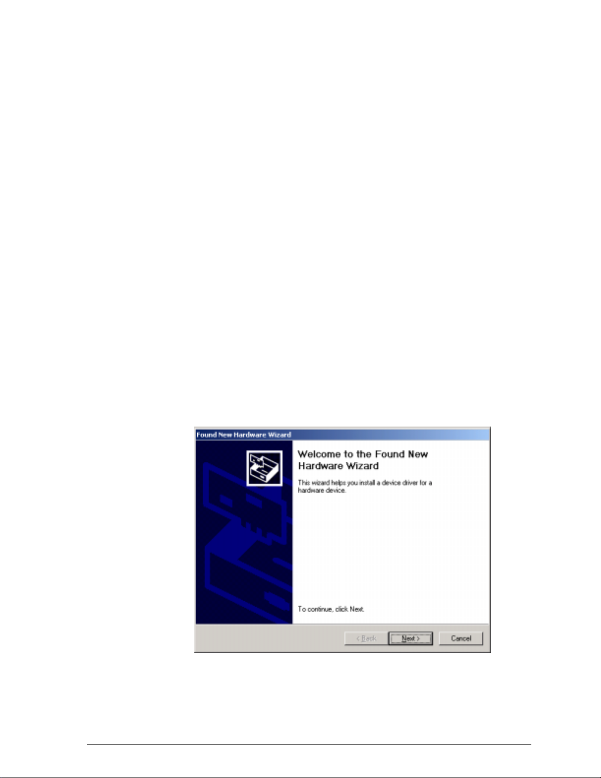
Insert the D-Link WMP-A12 Wireless Network mini PCI Card into a 32-bit
CardBus slot and follow t hese st eps to install the NDIS dr iver:
1. Wait for the following di alog box to display, and click Next to continue.
2
Page 26
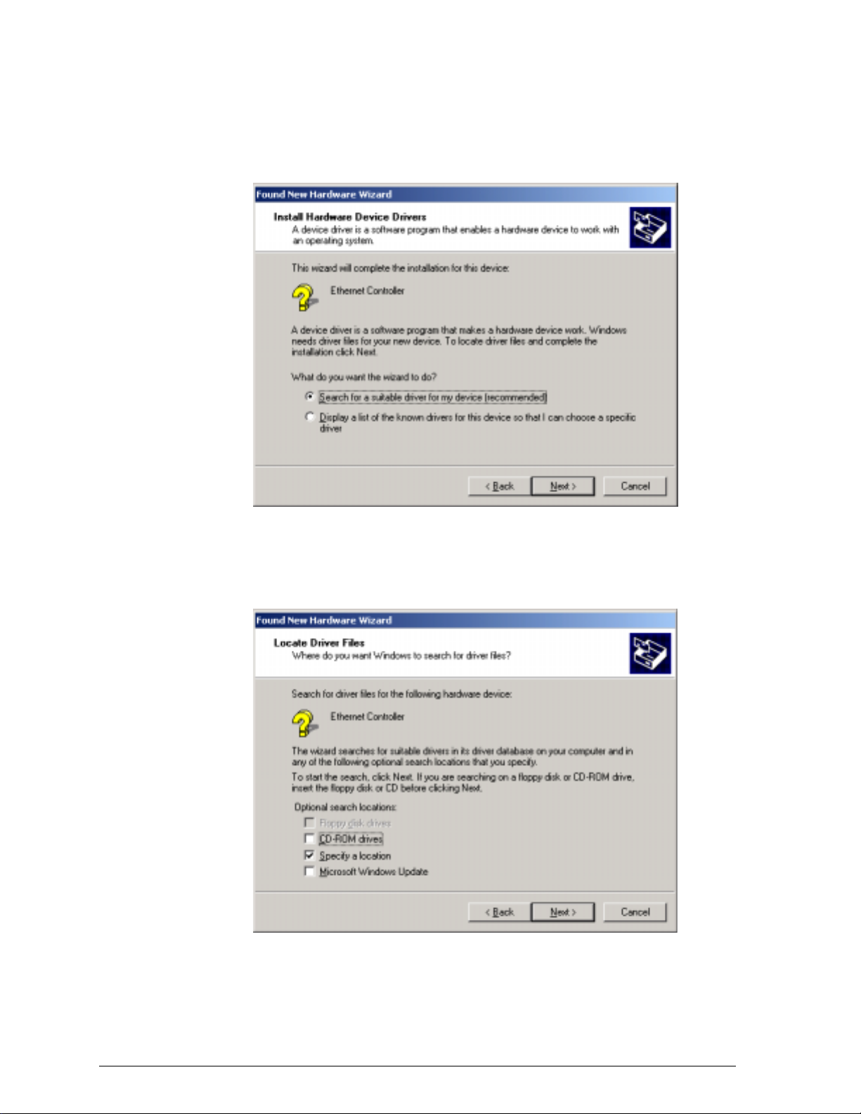
2. Choose “Search for a suita ble driver for my device (recommended),” and
click Next.
3. Insert the installation C D in your CD-ROM drive. Choose “Specify a
location” under “Optional se arch l ocations,” and click Next to continue.
Page 27
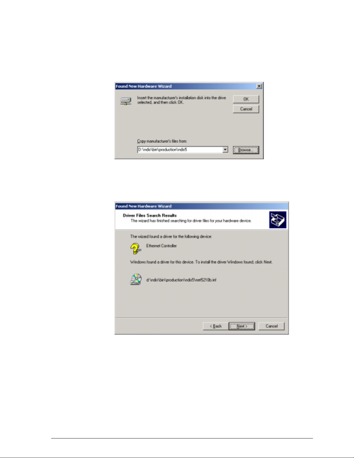
4. Browse to the location where the NDIS driver is locat ed (assuming D is
the CD-ROM drive), the defa ult folder is D:\ndis\bin\prod uct ion\ndis5.
Click OK to continue.
5. When you find the D-L ink driver installation f il e (net5210b.inf), click Next
to continue.
Page 28
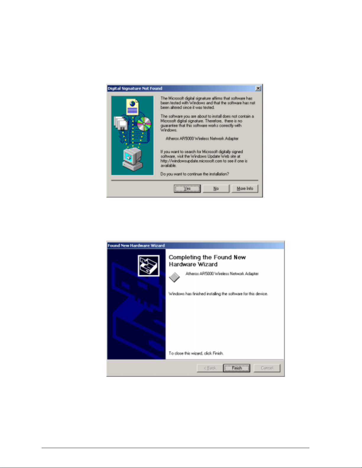
6. The D-Link NDIS evaluation driver currently does not have a digital
signature from Microsoft. Therefore, Windows 2000 shows a w arni ng
message. Click Yes to proceed wit h driver installation.
7. Click Finish t o complete the driver installation. See Section “Device
Configuration” for the device configuratio n.
Page 29
Driver Installation (Previous Driver Installed)
If the system already has a previous release of the D-Link NDIS inst alled,
Windows does not prompt for the dev ice driver when the WLAN Card is
inserted. Follow the steps below to update the NDIS driver:
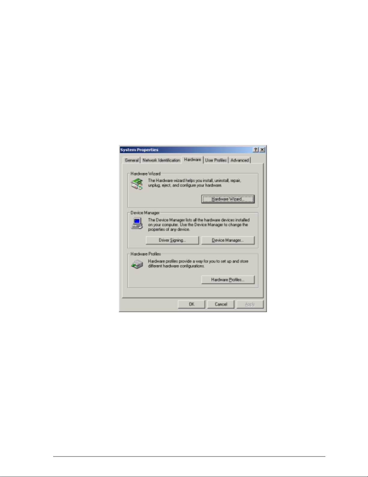
1. Start System Properti es from Control Panel. Under Hardware tab, click
Device Manager.
Page 30
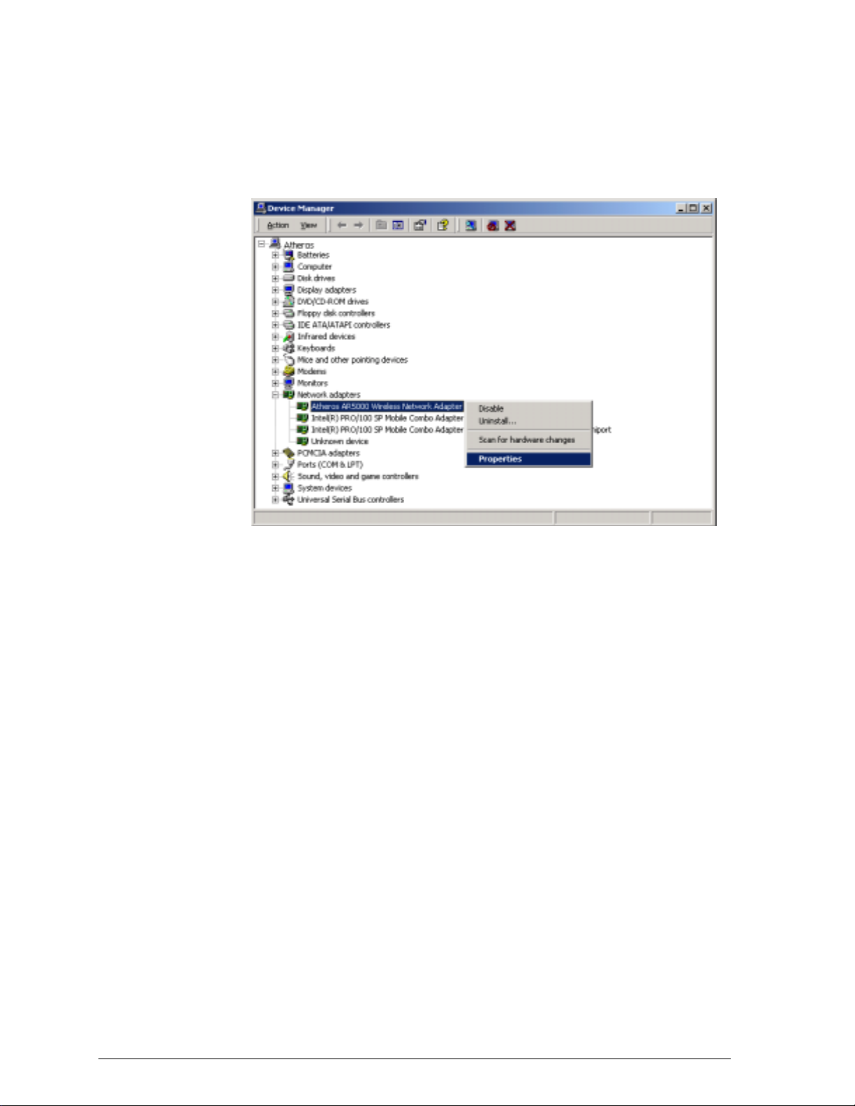
2. Within Device Manager, right -click “D-Link WMP-A12 Wireless Net w ork
mini PCI Card” under “Networ k adapt ers” device node, and click
Properties.
Page 31

3. Click “Update Driver…” from the Driver tab. Note the Driver Version that
you are updating from. You may need t o verify this field again after driv er
update completes to make sure Release 1.3 driver has bee n updated
correctly.
4. Click Next to continue.
Page 32

5. Choose “Display a list of the known drivers for this device so that I can
choose a specific driver,” and click Next to continue.
6. Insert the Release 1. 3 C D into your CD-ROM drive. Click “Have Disk…”
to continue.
Page 33

7. Browse to the location where the NDIS driver is loca t ed (assuming D is
the CD-ROM drive), the default folder is “D:\ndis\bin\production\ndis5”.
Click OK to continue.
8. Select “D-Link WMP-A12 Wireless Network mini PCI Card” from the list
and click Next to cont inue.
Page 34

9. Click Yes to contin ue when Windows displays t he w arning message.
Page 35

10. Click Next to proceed with instal lat ion.
11. The D-Link NDIS evaluation driv er current ly does not have a digital
signature from Microsoft. Therefore, Windows 2000 shows a w arni ng
message. Click Yes to proceed wit h driver installation.
Page 36

12. Click Finish.
13. Note that Driver Version should display 1.3 as the major revision number.
Click OK to continue.
Page 37

14. Click Yes to restart system.
15. After system restarts, the “D-Link WMP-A12 Wireless Network mini PCI
Card” now displays under “Network adapters” in the Device Manager.
Proceed to Section “Device Configuration” for device configuration
information.
Page 38

Driver Uninstallation
This section provides information about uninstallation procedure s required for
upgrading the NDIS driver from previ ous D-Link software releases. If the
system does not have previo usly installed versions of the N DIS driver and
you wish to remove the newly installed driver from the system, proc eed t o
Step 4.
The NDIS driver since Release 1.0 no longer leverages the Transport Driver
Interface (TDI) protocol to provide t he LinkMon programming interface. The
TDI protocol should be uninstalled. Follow t hese st eps to uninstall the TDI
protocol:
1. To remove the NDIS driver from the OS, go to Device Manager, rightclick “D-Link WMP-A12 Wireless Network mini P CI Card,” and choose
Uninstall.
Page 39

2. Click OK to uninst all the device.
3. When the device is uninstalled from Device Manager, search for and
delete the driver files that reside in the system. To do so, go to the Start
menu and choose Search For Fi les or Folders…, enter “oem*.inf” in the
“Search for files or folders named:” field, and ent er “D-Li nk” in the
“Containing text:” fie ld. Click Search Now. A few fi les matching these
criteria are possible, if previo us drivers have not been removed properly.
Choose the files that have been found and delete them from the system.
Page 40

4. To complete the uninsta llat io n, “ar5210b.sys” should also be removed
from the “\WINNT\system32\drivers” folder.
Page 41

Device Configuration
Configuration of the D-Link WMP-A12 Wireless Net w ork mini PCI Card can
be done through the Network Control Panel (NCP) in adapter pr operties. You
can set the Wireless Network mini PCI Card to wor k in one of two modes,
either infrastructure mode (which leverages an AP) or ad hoc mode (which
consists of a group of stations p art icipating in the WLAN).
In infrastructure mode, the Wireless Network mini PCI Card participates in a
basic service set (BSS) as a statio n, and communicates with the other
stations through an AP, as illustrated in Figure 2-1.
STA1
AP
Figure 2-1. Infrastructure Mode
STA2
Ethernet
Page 42

In ad hoc mode, a Wireless Network mini PCI Card works within an
independent basic service set (IBSS), as illust r at ed in Figure 2-2. All stati ons
communicate directly w it h ot her st at ions without an AP.
STA1
STA3
STA5
STA2
STA4
Figure 2-2. Ad Hoc Mode
To configure the WMP-A12 Wireless Networ k mini PC I Card:
1. In the Device Manager, right-click “D-Link WMP-A12 Wireless Network
mini PCI Card,” and click Properties to access the properties of the
adapter.
Page 43

2. Configuratio n additions, modifications, and deletions are made under the
“Settings” tab of the “D-Link WMP-A12 Wireless Network mini PCI Card”
properties.
3. Select one of the configurations under the config urat ion list, and click
Modify to show the “Network Configuration Settings” scre en. This
property sheet has two pages: General and Security. The General page
has the following fields :
− Configuration Na me: This field identifies the configuration. This name
must be unique. Conf iguration names are case insensitive.
− Network Name (SSID): This is the name of the I EE E 802.11a
wireless network, for example, “D-Lin k 802. 11a Wireless Network.”
This field has a maximum limit of 32 charact ers.
− Network Connection: This field defines whether the STA is configured
for an ad hoc or infrastructure network.
Page 44

− Power Saving: This field al l o w s the configuration of power
management options. The options are Off, Normal, and Max i mu m.
Power management is disabled when ad hoc mode is selected in the
Network Connection field. When the Power Saving setting is Off, the
adapter receives full power fro m the P C. When the Power Saving
setting is Normal, the driv er turns off power to the adapter for brief
periods over briefly-spaced ti me i nt ervals. When the Power Saving
setting is Maximum, the driver turns off pow er t o the adapter for
longer periods over more wide ly - spaced time intervals.
− Turbo Mode: This field ena bles or disables D-Link turbo mode.
− Locally Administered Address: This field defines the locally
administered MAC address (LA A). To ent er a value in the address
field, the check box needs to be s elected. Typically, an LAA is not
required, because the driv er automatically loads a un ique, globally
administered address from the EE PROM.
4. The next tab on this property sheet allows for the selection of security
features. The fields on this page are as follows:
− Enable Security: This field completely enables or disables the IEEE
802.11 wired equivalent privacy (WEP) security feature.
− Default Encryption Key: This field defines the type of encryption key
to use (either Unique Key or Shared Keys). This field allow s you to
select only a key (Unique, First, Second, Third, or Fourth) whose
corresponding field has been c ompleted.
Page 45

− Unique Key: This fie ld de f ines the unique encryption key for security
for the current network configuration. I n ad hoc mode, this encryption
key type is not used. To enabl e security using a Unique K e y, this field
must be populated.
− Shared Keys: These fields define a set of shared encryption key s.
To enable security usin g Shared Keys, at least one Share d Key field
must be populated.
− Key Length: This field defines t he length for each encryption key.
As the Key Length is changed, t he number of available characters in
the field is changed automat ically. If after a key is entered the length
is adjusted to a smaller number, t he key is automatically t r uncat ed t o
fit. If the length is increased again, the field is not automatically
updated to its previous value.
All encryption key fiel ds are displayed only when in itially entered. On
subsequent entry into the security property page, the fields are masked.
The keys must be entered as hex adecimal digits.
Page 46

Infrastructure Mode
To configure an D-Link WMP-A12 Wireless Networ k mini PCI Card in
infrastructure mode:
1. Ensure that the “Locally Administered Address” checkbox is unchecked.
2. Choose the follow ing settings:
− Configuration Na me: This field identifies t he configuration. This name
must be unique. Conf iguration names are case insensitive.
− Network Name (SSID): This is the name of the I EE E 802.11a
wireless network, for example, “D-Lin k 802. 11a Wireless Network.”
This field has a maximum limit of 32 c haract ers. I f t his field is left
blank, the STA connect s t o t he AP with the best signal strength.
− Network Connection: AP (infrastructure).
− Power Saving: This field al l o w s the configuration of power
management options. The options are Off, Normal, and Max i mu m.
− Turbo Mode: This field ena bles or disables D-Link turbo mode.
− Locally Administered Address: This field defines the locally
administered MAC address (LA A). To ent er a value in the address
field, the check box needs to be sel ect ed.
Page 47

Ad Hoc Mode
Usually infrastructure mo de i s used in an enterprise envir onment where APs
are installed and maintained by corporate IT staff. Much of the d at a in t he
enterprise network is confidential. It is important to configure security to make
sure only stations with appropriate keys can receive sensitive data. The DLink WMP-A12 Wireless Network mini PCI Card and NDIS driver support key
lengths of 40 bits, 104 bits, and 128 bits. Typically, the appropriate encryption
and decryption keys are suppli ed by the corporate IT staff.
An ad hoc network usually is a short-lived netw ork with a small number of
stations. The network is usually created for a special pur pose such as
exchanging data betwee n friends, or between customer and client. Because
the duration of the ad hoc network tends to be limited, Power Saving and
Security features are not ty pical ly a requirement. For ad hoc network activity ,
the Power Saving and Security features can be disabled. Currently , shared
key security is supported in ad ho c mode. Future D-Link software
implementations wi ll provide unique key supp ort.
In ad hoc mode, a station scans the air for an existing BSS. If no BSS i s
found, the station establi shes a BSS for other stations to join. When other
stations scan the air and find a n est ablished BSS in place, they join that BSS
to form an ad hoc network. If a specific set of stations requires a d hoc
network connectivity, it is recommended to have one station est ablish a BSS
first before configuring the remaining stations. This prevents t he scenario of
several stations trying to form a BSS at the same time, wh ich can result in
multiple singular BSS s being established, rather t han a single BSS with
multiple stations.
Configuration Na me: This field identifies the configuration. This name
"
must be unique. Conf iguration names are case insensitive.
Network Name (SSID): A Network Name is mandat ory for ad hoc mode.
"
The SSID for all stations in a single ad hoc network must be the same.
Network Connection: Ad Hoc.
"
Power Saving: Power saving mode is not current ly supported in an ad
"
hoc network.
Turbo Mode: All station s part icipating in the ad hoc networ k must have
"
the same rate setting.
Locally Administered Address: This field defines the locally administered
"
MAC address (LAA). To enter a value i n t he address field, the check box
needs to be selected.
Page 48

TCP/IP Setup
After configuring the D-Li nk WMP-A12 Wireless Network mini PCI Card
through the Network Control Panel, the TCP/IP address for the network
device must be configured.
1. Open the “Control Panel” and click “Network and Dial-up Connections.”
2. Find the “Local Area Connection” that is associated with the D-Link
WMP-A12 Wireless Network mini PCI Card. Ri ght -cl ick that connection,
and click Properties.
Page 49

3. Select “Internet Protocol (T CP/IP)” and click Properties.
4. Click “Use the foll owing IP address” and input an I P address and Subnet
mask. Assigning an IP addres s and Subnet mask allows stati ons t o
operate in infrastructure mod e and t o have Internet access. “Defau lt
gateway” and “DNS server” infor mation is also required. IP configuration
information (DHCP or ass ig ned I P address, Gateway and DNS server IP
addresses) is usually obtained fr om the corporate IT staff.
5. After obtaining IP configuration informat ion from the appropriate IT staff,
click OK in both “Internet Protocol (TCP/ I P) Pro pert i es” and “Local Area
Connection Properties” to compl et e t he I P configuration.
Page 50

6. Choose Start > Programs > Accessories > Command Prom pt t o open t he
DOS command prompt window . Type “ipconfig” at the C:\> pro mpt t o
determine if the TCP/IP con figuration has taken effect. To test I P
connectivity in ad hoc or infrast r uct ure mode, use the “ping <ipaddress>”
command. When a TCP/IP connection is established, the LinkMon utility
(See Chapter 7) can be used to monit or t he D-Link WMP-A12 Wireless
Network mini PCI Card operating status.
Page 51

7. To map the drive on anot her machine to your computer, right-click “My
Computer” and click “Map Netw ork Drive….”
8. After mapping the drive, you can perform file transfers, use video
streaming application s, and al l ot her network data transfers that are
normally performed with w ired 10/100 Ethernet conne ctions.
Page 52

Page 53

Windows Millennium
Driver Installation
D-Link recommends that you remov e any existing D-Link NDIS driver on the
PC system before insta lling new Version of the NDIS dr iver. See Section
“Driver Uninstallation” on page 3-5 for the instructions on how to re move
previous driver releases. When the system no longer has the D-Li nk NDIS
driver installed, insert t he WMP - A12 Wireless Networ k mini PCI Card into a
32-bit CardBus slot, and fo llow these steps to install the NDIS driver:
3
Edition
1. Wait for the following dialog box to appear. Choose “Spe cify the location
of the driver (Advanced),” and c l ick Next to continue.
Page 54

Page 55

2. Choose “Search for the best driv er for y our device. (Recommended)” and
select “Specify a location.” Click Browse to locate the NDIS driver. The
default folder is “E:\ndis\bin\production\ndis5” (assuming E: is the CDROM drive). Click Next to contin ue.
3. When the D-Link driver installation file (NET5 210B.INF) has been found,
click Next to continue.
Page 56

4. Click Finish to cont i nue, and restart the system to complete driver
installation. Refer to Section “Device Config uration” on page 3-7 for
device configuration.
Page 57

Driver Uninstallation
This section provides uninst al lat i on procedures for removing the D-Link NDIS
driver from the system. Uninst allation is recommended for upgrading the
NDIS driver from previous D-Link driver releases.
1. To remove the NDIS driv er from the OS, go to Start > Search > For Files
or Folders…, and search for the INF file containing the “D-Link” text string
under the \WINDO WS\INF folder. Be sure to include subfolders in the
search criteria. When “D-Lin knet 5210b.inf” has been found, del et e it by
right-clicking the file and choose Delete.
Page 58

2. From Control Panel, l aunch the System Properties w in dow. Select “DLink WMP-A12 Wireless Network mini PCI Card” from Device Manager,
and click Remove t o uninstall the device.
3. Click OK to confir m the removal of the device. Restart t he system to
complete un-inst allation.
Page 59

Device Configuration
Configuration of the D-Link WMP-A12 Wireless Net w ork mini PCI Card can
be done through the D-Link NIC Configuration uti lit y found in the Windows
Control Panel. Similar t o Win dows 2000, the device can be set to work in one
of two modes: infrastructure mode or ad hoc mode. Please refer to Section
“Device Configuration” beginning on page 2-17 f or more details on these
network connection types.
To launch the configur ation utility, go to Cont rol Panel and double-clic k on
the D-Link NIC Configur atio n icon .
Page 60

The configuration utility allows addition, modification, and deletion of the
configuration profiles. Select one of the existing configuration profiles under
the configuration list to modify, or click New to add a new configuration profile.
Follow Section “Infrastructure Mode” on page 3-9 and Section “Ad Hoc
Mode” on page 3-10 to set up the station t o work in infrastructure mode an d
ad hoc mode.
Page 61

Infrastructure Mode
This section defines the proc ess of configuring an D-Link WMP-A12 Wireless
Network mini PCI Card in infrastructure mod e. See Section “Dev ice
Configuration” beginning on page 2-17 for detailed descriptions of each
option in the Network Configuration Sett ings.
1. Under the “General” tab, make sure the “Locally Administered Address”
checkbox is unchecked. Use t he following informat ion as a guideline to
choose the values of each field in the configuration window :
− Configuration Na me: This field identifies t he configuration. This name
− Network Name (SSID): This is the name of the I EE E 802.11a
− Network Connection: AP (Infrastructure)
− Power Saving: This field al l o w s the configuration of power
must be unique. Conf iguration names are case insensitive.
wireless network. This field has a maximum limit of 32 characters. If
this field is left blank, the STA connects to the AP with the best signal
strength.
management options. The options are Off, Normal, and Max i mu m.
− Turbo Mode: This field ena bles or disables D-Link turbo mode.
Page 62

2. Usually, infrastr uct ure mode is used in an enterprise env ironment where
APs are installed and maint ained by corporate IT staff. Much of the data
in the enterprise network is confidential. It is imp ort ant t o configure
security to make sure only stations with appropriate keys can receive
sensitive data. The D-Link WMP-A12 Wireless N et work mini PCI Card
and NDIS driver support key lengths of 40 bits, 104 bits and 128 bits.
Typically, the appropriat e encryption and decryption key s are supplied by
the corporate IT staff.
Ad Hoc Mode
This section defines the proc ess of configuring an D-Link WMP-A12 Wireless
Network mini PCI Card in ad hoc or IBSS mode. See Section “Ad Hoc Mode”
on page 2-23 for descriptions of ad hoc operation.
1. Similar to the set-up of AP Infrast r ucture mode described in the prev ious
section, ad hoc mode is also configured by changing the options in the
Network Configuration Settings of the D-L ink NIC Configuration utility.
Use the following in formation as a guideline t o choose the values of each
field in the configuration w in dow:
− Configuration Na me: This field identifies t he configuration. This name
must be unique. Conf iguration names are case insensitive.
− Network Name (SSID): A Network Name is ma ndat ory for ad hoc
mode. The SSID for all stations in a single ad hoc networ k must be
the same.
− Network Connection: Ad Hoc.
Page 63

− Power Saving: Power saving mode is not currently supported in an ad
hoc network.
− Turbo Mode: All station s part icipating in the ad hoc networ k must
have the same rate setting.
− Locally Administered Address: This field defines the locally
administered MAC address (LA A). To ent er a value in the address
field, the check box needs to be sel ect ed.
2. You can optionally set up ot her properties, but because the duration of
the ad hoc network tends to be li mit ed, Power Saving and Security
features are not typically a requirement. For ad hoc network activity, the
Power Saving and Security features can be disabled. Currently, shared
key security is supported in ad ho c mode. Future D-Link software
implementations wi ll provide unique key supp ort.
3. Click OK when the propert i es are set correctly. The system needs to
reboot in order for the changes to take effect.
Note that in ad hoc mode, a station scans the air for an existing BSS. If no
BSS is found, the statio n est ablishes a BSS for other stations t o join. When
other stations scan the air and f ind an established BSS in p lace, they join that
BSS to form an ad hoc networ k. I f a spe ci fi c set of stat i ons requires ad hoc
network connectivity, it is recommended to have one station est ablish a BSS
first before configuring the re mai ning stations. This prevents t he scenario of
several stations trying to form a BSS at the same time, wh ich can result in
multiple singular BSS s being established, rather t han a single BSS with
multiple stations.
Page 64

TCP/IP Configuration
After configuring the D-Li nk WMP-A12 Wireless Network mini PCI Card
network adapter properties, the T C P/ I P address for the network device needs
to be configured.
1. From Control Panel, l aunch the Network properties w indow. Select
“TCP/IP → D-Link WMP-A12 Wireless Network mini PCI Card” and click
Properties. Depending on t he t ype of network the station connects t o,
Gateway and DNS Co nf iguration information can also be required.
IP configuration information (DHCP or assigned IP address, Gateway and
DNS server IP addresses) is usua lly obtained from the corporate IT sta ff.
For a simple demonstration, the st at ion is assigned a static IP address.
From “TCP/IP Properties,” choose “I P Address” and select “Specify an IP
address.” Input an IP address and subnet mask. Assigning an IP address
and subnet mask allows the stat i on to interact with the AP or other
stations in the same IP subnet. Click OK to complete the TCP/IP
configuration, and restart the sy st em for the changes to take effect.
Page 65

2. Choose Start > Programs > Accessories > Command Prompt t o open the
DOS command prompt window . Type “ipconfig” to determine if the
TCP/IP configuratio n has t aken effect. To test IP connectivity in ad hoc or
infrastructure mode, use the “ping <ipaddress>” command. When a
TCP/IP connection is est ablished, the LinkMon uti lit y (see Chapter 7) can
be used to monitor the D-Link WMP-A12 Wireless Network mini PCI Card
operating status.
Page 66

3. To map the drive on anot her machine to your computer, right-click “My
Computer” and click “Map Netw ork Drive….” Specify t he pat h of a
network-shared folder.
4. After mapping the drive, you can perform file transfers, video streaming,
and all other network data tr ansfers that are normally performed with
wired 10/100 Ethernet connections.
Page 67

Windows 98 Second
Driver Installation
D-Link recommends that you remov e any existing D-Link NDIS driver on the
PC system before insta l ling Version 1.3 release of the NDIS driver.
See Section “Driver Uninstallation” on page 4-5 for the instructi ons on how to
remove previous driver releas es. When the system no longer has the D-Li nk
NDIS driver installed, insert the WMP-A12 Wireless Network mini PCI Card
into a 32-bit CardBus slot, and f ollow these steps to install t he N DIS driver:
4
Edition
1. Wait for the following di al og box to appear, and click Next t o cont inue.
Page 68

Page 69

2. Choose “Search for the best driver for your device. (Recommended),”
and click Next.
3. Insert the D-Link Software Release CD in your C D-ROM drive. Choose
“Specify a location” and browse to the location where the NDIS driver is
located. The default fo lder is D:\ndis\bin\product i on\ndis5 (assuming D: is
the CD-ROM drive). Cl ick Next to continue.
Page 70

4. When the D-Link driver installation file (NET5 210B.INF) has been found,
click Next to continue.
5. Click Finish t o cont inue.
Page 71

6. Click Yes to restart the sy st em a nd complete driver installation.
See Section “Device Configuration” on page 4-8 for dev ice configuration.
Driver Uninstallation
This section provides uninst al lat i on procedures for removing the D-Link NDIS
driver from the system. Uninst allation is recommended for upgrading the
NDIS driver from previous D-Link driver releases.
1. To remove the NDIS driv er from the OS, go to Start > Search > For Files
or Folders…, and search for the INF file containing the “D-Link” text string
under the \WINDO WS\INF folder. Be sure to include subfolders in the
search criteria.
Page 72

2. When “D-Linknet52 10b.inf” has been found, delet e it by right-clicking the
file and choose “Delete.”
Page 73

3. From Control Panel, l aunch the Network properties w indow. Select “D-
Link WMP-A12 Wireless Network mini PCI Card” from t he list, and click
Remove to uninstall the device.
4. Click OK to confir m the removal of the device. Restart t he system to
complete uninstal lat ion.
Page 74

Device Configuration
Configuration of the D-Link WMP-A12 Wireless Net w ork mini PCI Card can
be done through the D-Link NIC Configuration utility found in the Windows
Control Panel. Similar t o Windows 2000 the device can be s et t o work in one
of two modes: infrastructure mode or ad hoc mode. Please refer to Section
“Device Configuration” beginning on page 2-17 f or more details on these
network connection types.
To launch the configur ation utility, go to Cont rol Panel and double-clic k on
the D-Link NIC Configur atio n icon .
The configuration utility allows addition, modification, and deletion of the
configuration profiles. Select one of the existing configuration profiles under
the configuration list to modify, or click New to add a new configuration profile.
Follow Section “Infrastructure Mode” on page 4-9 and Section “Ad Hoc
Mode” on page 4-11 to set up the station t o work in infrastructure mode an d
ad hoc mode.
Page 75

Infrastructure Mode
This section defines the proc ess of configuring an D-Link WMP-A12 Wireless
Network mini PCI Card in infrastructure mod e. See Section “Dev ice
Configuration” beginning on page 2-17 for detailed descriptions of each
option in the Network Configuration Sett ings.
1. Under the “General” tab, make sure the “Locally Administered Address”
checkbox is unchecked. Use t he following informat ion as a guideline to
choose the values of each field in the configuration window :
− Configuration Na me: This field identifies t he configuration. This name
− Network Name (SSID): This is the name of the I EE E 802.11a
− Network Connection: AP (Infrastructure)
− Power Saving: This field al l o w s the configuration of power
must be unique. Conf iguration names are case insensitive.
wireless network. This field has a maximum limit of 32 characters. I f
this field is left blank, the STA connects to the AP with the best signal
strength.
management options. The options are Off, Normal, and Max i mu m.
− Turbo Mode: This field ena bles or disables D-Link turbo mode.
Page 76

2. Usually, infrastr uct ure mode is used in an enterprise env ironment where
APs are installed and maint ained by corporate IT staff. Much of the data
in the enterprise network is confidential. It is imp ort ant t o configure
security to make sure only stations with appropriate keys can receive
sensitive data. The D-Link WMP-A12 Wireless N et work mini PCI Card
and NDIS driver support key lengths of 40 bits, 104 bits, and 128 bits.
Typically, the appropriat e encryption and decryption key s are supplied by
the corporate IT staff.
Page 77

Ad Hoc Mode
This section defines the proc ess of configuring an D-Link WMP-A12 Wireless
Network mini PCI Card in ad hoc or IBSS mode. See Section “Ad Hoc Mode”
on page 2-23 for descriptions of ad hoc operation.
1. Similar to the setup of the A P infrastructure mode described in the
previous section, ad hoc mode is also configured by changing the
Network Configuration Settings of the D-L ink NIC Configuration utility.
Use the following in formation as a guideline t o choose the values of each
field in the configuration w in dow:
− Configuration Na me: This field identifies t he configuration. This name
must be unique. Conf iguration names are case insensitive.
− Network Name (SSID): A Network Name is ma ndat ory for ad hoc
mode. The SSID for all stations in a single ad hoc networ k must be
the same.
− Network Connection: Ad Hoc.
− Power Saving: Power saving mode is not currently supported in an ad
hoc network.
− Turbo Mode: All station s part icipating in the ad hoc networ k must
have the same rate setting.
− Locally Administered Address: This field defines the locally
administered MAC address (LA A). To ent er a value in the address
field, the check box needs to be sel ect ed.
Page 78

2. You can optionally set up ot her properties, but because the duration of
the ad hoc network tends to be li mit ed, Power Saving and Security
features are not typically a requirement. For ad hoc network activity, the
Power Saving and Security features can be disabled. Currently, shared
key security is supported in ad ho c mode. Future D-Link software
implementations wi ll provide unique key supp ort.
3. Click OK when the propert i es are set correctly. The system needs to
reboot in order for the changes to take effect.
Note that in ad hoc mode, a station scans the air for an existing BSS. If no
BSS is found, the statio n est ablishes a BSS for other stations t o join. When
other stations scan the air and f ind an established BSS in p lace, they join that
BSS to form an ad hoc networ k. I f a spe ci fi c set of stat i ons requires ad hoc
network connectivity, it is recommended to have one station est ablish a BSS
first before configuring the remaining stations. This prevents t he scenario of
several stations trying to form a BSS at the same time, wh ich can result in
multiple singular BSS s being established, rather t han a single BSS with
multiple stations.
Page 79

TCP/IP Setup
After configuring the D-Li nk WMP-A12 Wireless Network mini PCI Card
network adapter properties, the T C P/ I P address for the network device needs
to be configured.
1. From Control Panel, l aunch the Network properties w indow. Select
“TCP/IP → D-Link WMP-A12 Wireless Network mini PCI Card” and click
Properties. Depending on t he t ype of network the station connects t o,
Gateway and DNS Co nf iguration information can also be required.
IP configuration information (DHCP or assigned IP address, Gateway and
DNS server IP addresses) is usua lly obtained from the corporate IT staff.
For a simple demonstration, the st at ion is assigned a static IP address.
From “TCP/IP Properties,” choose “I P Address” and select “Specify an IP
address.” Input an IP address and subnet mask. Assigning an IP address
and subnet mask allows the stat i on to interact with the AP or other
stations in the same IP subnet. Click OK to complete the TCP/IP
configuration, and restart the sy st em for the changes to take effect.
Page 80

2. Choose Start > Programs > Accessories > Command Prom pt t o open t he
DOS command prompt window . Type “ipconfig” to determine if the
TCP/IP configuratio n has t aken effect. To test IP connectivity in ad hoc or
infrastructure mode, use the “ping <ipaddress>” command. When a
TCP/IP connection is est ablished, the LinkMon uti lit y (see Chapter 7) can
be used to monitor the D-Link WMP-A12 Wireless Network mini PCI Card
operating status.
Page 81

3. To map the drive on anot her machine to your computer, right-click “My
Computer” and click “Map Netw ork Drive….” Specify t he pat h of a
network-shared folder.
4. After mapping the drive, you can perform file transfers, video streaming,
and all other network data tr ansfers that are normally performed with
wired 10/100 Ethernet connections.
Page 82

Page 83

Windows XP
Driver Installation (First-time Install)
D-Link recommends that you remov e any existing D-Link drivers on the P C
system before installing Versio n 錯誤! 找不到參照來源。 release of the NDIS
driver. See Section “Driv er Uni nst allation” on page 5-6 for the instructions on
how to remove previous driv er releases. With no existing D-Lin k NDIS driver
installed, insert the D-Link WMP-A12 Wireless Network m ini PCI Card into a
32-bit CardBus slot, and follow these steps to install t he NDIS driver:
1. Wait for the following dialog box to appear. Choose “Insta ll from a list or
specific location (Advanced),” and click Next to cont inue.
5
Page 84

Page 85

2. Under “Search for the best driv er in t hese locations,” choose “Include this
location in the search” and click Browse to find the location of the NDIS
driver. When the driver locat i on has been identified, click Next to continue.
Page 86

3. The D-Link NDIS evaluation driver currently does not have a digital
signature from Microsoft. Therefore, Windows XP shows a warni ng
message. Click Continue Anyway to proceed with driver inst al lation.
4. Click Finish to complete driver installation, and refer to Section “Device
Configuration” on pa ge 5-10 for device configuration.
Page 87

Page 88

Driver Uninstallation
This section provides uninst al lat i on procedures for removing the D-Link NDIS
driver from the system. Uninst allation is recommended for upgrading the
NDIS driver from previous D-Link driver releases.
1. To remove the NDIS driver from the OS, go to Device Manager, right
click “D-Link WMP-A12 Wireless Network mini P CI Card,” and choose
Uninstall.
2. Click OK to uninst all the device.
Page 89

Page 90

3. When the device is uninstalled from Device Manager, search for and
delete the driver installati on file that resides in the system. To do so, go t o
Start and choose Search > Al l f iles and folder, enter “oem*.inf” in t he “Al l
or part of the file name” field, and enter “D-Link” in the “A w ord or phrase
in the file” field. Enter “C:\WINNT\INF” in the “Look in” field, where C: is
the drive letter of where Windows XP is installed. Click Search to find the
driver installation file.
4. A file matching the se arch criteria is displayed. Choose this file and
delete it from the system.
Page 91

Page 92

Device Configuration
Windows XP zero-configuration functionality allows the user to select and join
a wireless network without having to configure the device separately. You
can decide to choose the default parameters and directly proceed to zeroconfiguration in Section “Windows XP Wireless Networ k Configuration” on
page 5-20.
Similar to Windows 2000, con f iguration of the D-Link WMP-A12 Wireless
Network mini PCI Card c an be done through the Networ k Cont rol Panel
(NCP) in adapter properties. You can set t he Wireless Network mini PCI
Card to work in one of two modes: infrastructure mode or ad hoc mode. See
Section “Device Conf iguration” beginning on pa ge 2-17 for more details on
these network connection t ypes.
To launch NCP go to Device Manager, right-click “D-Link WMP-A12 Wireless
Network mini PCI Card,” and select Properties to access to the propert ies of
the adapter.
Page 93

Configuration add it ions, modifications, and deletions are made under the
“Settings” tab of “D-Link WMP-A12 Wireless Network mini PCI Card
Properties.” Select one o f the configurations under the con f iguration, click
Modify or New and complete the steps in Section “Infrastructure Mode” on
page 5-12 or Section “Ad Hoc Mode” on page 5-13 to set up the station to
work in infrastructure mode or ad hoc mode, respectively.
Page 94

Infrastructure Mode
This section defines the proc ess of configuring an D-Link WMP-A12 Wireless
Network mini PCI Card in infrastructure mod e. See Section “Dev ice
Configuration” beginning on page 2-17 for detailed descriptions of each
option in the Network Configuration Sett ings.
1. Under the “General” tab, make sure t he “Locally Administered Address”
checkbox is unchecked. Use t he following informat ion as a guideline to
choose the values of each field in the configuration window :
− Configuration Na me: This field identifies t he configuration. This name
− Network Name (SSID): This is the name of the I EE E 802.11a
− Network Connection: AP (Infrastructure).
− Power Saving: This field al l o w s the configuration of power
must be unique. Conf iguration names are case insensitive, for
example, “Infrastructure.”
wireless network, for example, “AP_ N et w ork.” This field has a
maximum limit of 32 characters. If this field is left blank, the STA
connects to the AP with the best si gnal strength.
management options. The options are Off, Normal, and Max i mu m.
− Turbo Mode: This field ena bles or disables D-Link turbo mode.
Page 95

2. Usually, infrastr uct ure mode is used in an enterprise env ironment where
APs are installed and maint ained by corporate IT staff. Much of the data
in the enterprise network is confidential. It is imp ort ant t o configure
security to make sure only stations with appropriate keys can receive
sensitive data. The D-Link WMP-A12 Wireless N et work mini PCI Card
and NDIS driver support key lengths of 40 bits, 104 bits and 128 bits.
Typically, the appropriat e encryption and decryption key s are supplied by
the corporate IT staff.
Ad Hoc Mode
This section defines the proc ess of configuring an D-Link WMP-A12 Wireless
Network mini PCI Card in ad hoc or IBSS mode. See Section “Ad Hoc Mode”
on page 2-23 for descriptions of ad hoc operation.
1. Similar to the setup of AP Infrastructure mode described in t he previous
section, ad hoc mode is also configured by changing the options in the
“Network Configurat ion Settings” window. Use the following inform at ion
as a guideline to choose the values of each field in the configuration
window:
− Configuration Na me: This field identifies t he configuration. This name
must be unique. Conf iguration names are case insensitive, for
example, “Ad Hoc.”
Page 96

− Network Name (SSID): A Network Name is ma ndat ory for ad hoc
mode. The SSID for all stations in a single ad hoc networ k must be
the same.
− Network Connection: Ad Hoc.
− Power Saving: Power saving mode is not currently supported in an ad
hoc network.
− Turbo Mode: All station s part icipating in the ad hoc networ k must
have the same rate setting.
− Locally Administered Address: This field defines the locally
administered MAC address (LA A). To ent er a value in the address
field, the check box needs to be sel ect ed.
2. You can optionally set up security features, but it is not typically a
requirement because the duration of the ad hoc network tends to be
limited. Currently, shared key security is supported in ad hoc mod e.
Future D-Link software implementations will provide unique key support.
Page 97

TCP/IP Setup
3. In ad hoc mode, a station sc ans the air for an existing BSS. If no BSS is
found, the station establi shes a BSS for other stations to join. When other
stations scan the air and find an established BSS in place, they join that
BSS to form an ad hoc networ k. I f a spe ci fi c set of stat i ons requires ad
hoc network connectivity, it is recommended to have one station establish
a BSS first before configuring t he remaining stations. Thi s prevents the
scenario of several statio ns t r ying to form a BSS at the same time, whi ch
can result in multiple singular BSSs being established, rather than a
single BSS with multip le stations.
After configuring the D-Li nk WMP-A12 Wireless Network mini PCI Card
through the Network Control Panel, the TCP/IP address for the network
device needs to be configure d.
1. From the Start menu, choos e Programs > Accessories >
Communications > Network Connections. Find the “Local Area
Connection” that is associated with the D-Link WMP-A12 Wireless
Network mini PCI Card. Right-click that conne ct ion and click Properties.
Page 98

2. Select “Internet Protocol (TCP/IP)” and click Properties. Click “Use the
following IP address” an d input an IP address and Subnet mask.
Depending on the type of n etwork the station connects t o, G a t ew ay and
DNS Configuration information can also be required. IP configuration
information (DHCP or ass ig ned I P address, Gateway and DNS server IP
addresses) is usually obtained fr om the corporate IT staff. For a simple
demonstration, the st at ion i s assigned a static IP address. Cli ck OK in
both “Internet Protocol (TCP/I P) Properties” and “Local Area Connection
Properties” to complete the IP configurat i on.
Page 99

3. Choose Start > Programs > Accessories > Command Prom pt t o open a
command prompt window. Type “ipconfig” to determine if the TCP/ I P
configuration has taken effect. To t est I P connectivity in ad hoc or
infrastructure mode, use the “ping <IP address>” command. When a
TCP/IP connection is est ablished, the LinkMon uti lit y (see Chapter 7) can
be used to monitor the operating stat us of D-Link WMP-A12 Wireless
Network mini PCI Card.
Page 100

4. To map the drive on anot her machine to your computer, from the Start
menu, choose My Computer and right -click to select “Map Network
Drive….”
 Loading...