

Page 1

D-Link AirPlus Xtreme G
DWA-520
Wireless PCI Adapter
Manual
TM
Rev. A1
Building Networks for People
Page 2

Content s
Package Contents ................................................................................3
Introduction............................................................................................4
Wireless Basics....................................................................................6
Getting Started......................................................................................9
Using the Configuration Utility..............................................................12
Networking Basics ..............................................................................26
Troubleshooting...................................................................................39
T echnical S pecifications ......................................................................44
Contacting T echnical Support ..............................................................46
Warranty and Registration ...................................................................47
2
Page 3

Package Contents
Contents of Package:
D-Link AirPlus Xtreme G DWA-520
!
Wireless PCI Adapter
Manual and Drivers on CD
!
Quick Installation Guide
!
TM
If any of the above items are missing, please contact your reseller.
System Requirements:
A computer or laptop with an available 32-bit PCI slot
!
Windows XP/2000/Me/98SE
!
At least 32 MB of memory and a 300 MHz processor
!
An 802.11g or 802.11b Access Point (for Infrastructure mode), or
!
another 802.11g or 802.11b wireless adapter (for Ad-Hoc, Peer-to-
Peer networking mode).
3
Page 4

Introduction
The D-Link AirPlus Xtreme G DWA-520 Wireless PCI Adapter is an 802.11g highperformance, wireless adapter that supports high-speed wireless networking at home,
at work or in public places.
Unlike most network cards, the DWA-520 provides data transfers at up to 54 Mbps.
The 802.1 1g standard is backwards compatible with 802.1 1b products.
The DWA-520 has the newest, strongest, and most advanced security features available
today. When used with other 802.11 WPA/WPA2 (Wi-Fi Protected Access) and 802.1x
compatible products in a network with a RADIUS server, the security features include:
WPA/WPA2: Wi-Fi Protected Access which authorizes and identifies users based on a
secret key that changes automatically at regular intervals. WPA/WPA2 uses
TKIP to change the temporal key every 10,000 packets (a packet is a kind of
message transmitted over a network.) This ensures much greater security
than the standard WEP security. (By contrast, the older WEP encryption req-
uired the keys to be changed manually.)
802.1x: Authentication which is a first line of defense against intrusion. In the
authentication process, the Authentication Server* verifies the identity of the
client attempting to connect to the network. Unfamiliar clients would be denied
access.
For home users that will not incorporate a RADIUS server in their network, the security
for the DWA-520, used in conjunction with other WPA/WPA2-compatible 802.11 prod-
ucts still be much stronger than ever before. Utilizing the Pre Shared Key mode of
WPA/WAP2 the DWA-520 will obtain a new security key every time it connects to
the 802.11 network. You only need to input your encryption information once in the
configurationmenu. No longer will you have to manually input a new WEP key frequently to ensure security. With the DWA-520, you will automatically receive a new key
every time you connect, vastly increasing the safety of your communication.
TM
* Not all servers can provide Authentication.
4
Page 5

Features & Benefits
Five times faster - achieve data transfer speeds up to 54 Mbps; up to 5x
!
faster than conventional 802.1 1b networks, when used with other 802.1 1g
devices
Fully compliant with the 802.11b standard and interoperable with all
!
existing 802.1 1b-compliant and 802.11g compliant devices
Provides a simple and inexpensive way to connect your desktop com-
!
puter to a wireless network at home, at the office, or in public places
Quick and Easy Installation- The DWA-520 installs quickly and easily into a
!
standard PCI 2.2 slot in a desktop computer. By following the simple steps
outlined in the Quick Installation Guide, you can connect to an available wire-
less network in a matter of seconds
High Performance 32-bit PCI - The high capacity PCI interface utilized by the
!
DWA-520 ensures optimal performance in transmitting a wireless signal within
the desktop computer. By utilizing a standard PCI 2.2 interface, the DWA-520
ensures a wide range of compatibility with motherboards used by PC manufacturers
Operates in the 2.4GHz frequency range
!
Maximum reliability, throughput and connectivity with automatic data rate
!
switching
Supports Infrastructure networks via an access point and Peer-to-Peer
!
communication in Ad-Hoc mode
User-friendly configuration and diagnostic utilities
!
Provides a measure of security for the information transmitted over a
!
wireless network with high data encryption at 64-, 128-, and 152-bit WEP
Stronger Security than ever before with WPA/WPA2 - Wi-Fi Protected
!
Access authorizes and identifies users based on a secret key that changes
automatically at regular intervals, for example:
TKIP (Temporal Key Integrity Protocol), in conjunction with a RADIUS
!
server, changes the temporal key every 10,000 packet s, ensuring greater
security
Pre-Shared Key mode means that the home user, without a RADIUS
!
server, will obt ain a new security key every time he or she connect s to
the network, vastly improving the safety of communications on the network
Extra Protection - 802.1x Authentication in conjunction with the RADIUS
!
server verifies the identity of wireless clients wishing to gain access to the
WLAN
5
Page 6

Wireless Basics
D-Link wireless products are based on industry standards to provide easy-to-use and
compatible high-speed wireless connectivity within your home, business or public access
wireless networks. D-Link wireless products will allow you access to the data you want,
when and where you want it. Y ou will be able to enjoy the freedom that wireless networking
brings.
A Wireless Local Area Network (WLAN) is a computer network that transmits and receives
data with radio signals instead of wires. WLANs are used increasingly in both home and
office environments, and public areas such as airports, coffee shops and universities.
Innovative ways to utilize WLAN technology are helping people to work and communicate
more efficiently. Increased mobility and the absence of cabling and other fixed
infrastructure have proven to be beneficial for many users.
Wireless users can use the same applications they use on a wired network. Wireless
adapter cards used on laptop and desktop systems support the same protocols as
Ethernet adapter cards.
People use WLAN technology for many different purposes:
Mobility - Productivity increases when people have access to data in any location
within the operating range of the WLAN. Management decisions based on real-time
information can significantly improve worker efficiency .
Low Implementation Costs – WLANs are easy to set up, manage, change and
relocate. Networks that frequently change can benefit from WLANs ease of implementation.
WLANs can operate in locations where installation of wiring may be impractical.
Installation and Network Expansion - Installing a WLAN system can be fast
and easy and can eliminate the need to pull cable through walls and ceilings. Wireless
technology allows the network to go where wires cannot go - even outside the home or
office.
Scalability – WLANs can be configured in a variety of ways to meet the needs of
specific applications and installations. Configurations are easily changed and range
from peer-to-peer networks suitable for a small number of users to larger infrastructure
networks to accommodate hundreds or thousands of users, depending on the number of
wireless devices deployed.
Inexpensive Solution - Wireless network devices are as competitively priced as
conventional Ethernet network devices.
6
Page 7

Wireless Basics (continued)
The DWA-520 is compatible with 802.11g and 802.11b wireless products, which include:
D-Link Air DWL-650,D-Link AirPlus DWL-650+,
!
D-Link AirPlus Xtreme G DWL-G650
2.4GHz Wireless Cardbus Adapter used with laptop computers
D-Link Air DWL-520, D-Link AirPlus DWL-520+
!
2.4GHz Wireless PCI cards used with desktop computers
D-Link AirPlus DWL-900AP+, D-Link AirPlus Xtreme G DWL-2000AP
!
2.4GHz Wireless Access Points
D-Link AirPlus DI-614+, DI-714P+
!
2.4GHz Wireless Routers
TM
TM
Standards-Based Technology
The DWA-520 Wireless PCI Adapter utilizes the new 802.11g standard.
The IEEE 802.11g standard is an extension of the 802.11b standard. It increases the
data rate up to 54 Mbps within the 2.4GHz band, utilizing OFDM technology .
This means that in most environments, within the specified range of this device, you will
be able to transfer large files quickly or even watch a movie in MPEG format over your
network without noticeable delays. This technology works by transmitting high-speed
digital data over a radio wave utilizing OFDM (Orthogonal Frequency Division Multiplexing)
technology. OFDM works by splitting the radio signal into multiple smaller sub-signals
that are then transmitted simultaneously at different frequencies to the receiver . OFDM
reduces the amount of crosstalk (interference) in signal transmissions. The D-Link DWLG520 will automatically sense the best possible connection speed to ensure the greatest
speed and range possible.
802.11g of fers the most advanced network security features available today , including:
WPA/WPA2,802.1x,TKIP,AES and Pre-Shared Key mode. These security feature
are explained in more detail in the Introduction and the Features section of this manual.
The DWA-520 is backwards compatible with 802.11b devices. This means that if you
have an existing 802.11b network, the devices in that network will be compatible with
802.1 1g devices at speeds up to 1 1Mbps in the 2.4GHz range.
7
Page 8

Wireless Basics (continued)
Installation Considerations
The D-Link AirPlus Xtreme G DWA-520 lets you access your network using a
wireless connection from virtually anywhere within its operating range. Keep in mind,
however, that the number , thickness and location of walls, ceilings, or other objects that
the wireless signals must pass through, may limit the range. T ypical ranges vary depending
on the types of materials and background RF (radio frequency) noise in your home or
business. The key to maximizing wireless range is to follow these basic guidelines:
Keep the number of walls and ceilings between the DWA-520 and other network
1
devices to a minimum - each wall or ceiling can reduce your DWA-520’s
range from 3-90 feet (1-30 meters.) Position your devices so that the number of
walls or ceilings is minimized.
Be aware of the direct line between network devices. A wall that is 1.5 feet thick
2
(.5 meters), at a 45-degree angle appears to be almost 3 feet (1 meter) thick. At
a 2-degree angle it looks over 42 feet (14 meters) thick! Position devices so
that the signal will travel straight through a wall or ceiling (instead of at an
angle) for better reception.
3
Building materials can impede the wireless signal - a solid metal door or aluminum
studs may have a negative effect on range. Try to position wireless devices and
computers with wireless adapters so that the signal passes through drywall or
open doorways and not other materials.
4
Keep your product away (at least 3-6 feet or 1-2 meters) from electrical
devices or appliances that generate RF noise.
TM
8
Page 9

Getting Started
With its default settings, the DWA-520, when activated, will connect
with other D-Link AirPlus Xtreme G products, right out of the box.
There are basically two modes of networking:
Infrastructure – using an Access Point or Router , such as
!
the DI-624
Ad-Hoc – directly connecting to another computer, for peer-to-
!
peer communication, using wireless network adapters on
each computer, such as two or more DWA-520 wireless
network adapters
On the following pages we will show you an example of an Infrastructure Network
and an Ad-Hoc Network.
An Infrastructure network contains an Access Point or Router . The Infrastructure
Network example shown on the following page contains the following D-Link network
devices (your existing network may be comprised of other devices):
A wireless Router - D-Link AirPlus Xtreme G DI-624
!
A desktop computer with a wireless adapter -
!
D-Link AirPlus Xtreme G DWA-520, D-Link Air DWL-520,
TM
TM
TM
or D-Link AirPlus DWL-520+
(D-Link Air devices have speeds up to 11Mbps)
A Cable modem - D-Link DCM-201
!
LEDs
LED stands for
Light-Emitting
Diode.
Power: Solid green light indicates connection to the network
Network: Blinking green light indicates activity on the network
9
Page 10
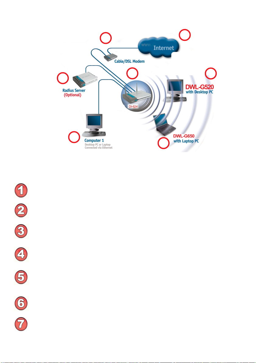
Getting Started (continued)
Setting up a Wireless Infrastructure Network
2
1
7
3
4
6
5
Please remember that D-Link AirPlus Xtreme G wireless devices are pre-
configured to connect together, right out of the box, with their default settings.
For a typical wireless setup at home (as shown above), please do the following:
You will need broadband Internet access (a Cable or DSL-subscriber line into
your home or office).
Consult with your Cable or DSL provider for proper installation of the modem.
Connect the Cable or DSL modem to your broadband router (see the Quick
Installation Guide included with your router.)
Install the D-Link DWA-520 Wireless PCI Adapter into an
available PCI slot on your desktop computer. (See the Quick Installation Guide
included with the DWA-520.)
Install the D-Link AirPlus Xtreme G DWL-G650 Wireless PC Card Adapter
into a laptop computer.
(See the Quick Installation Guide included with the DWL-G650.)
TM
TM
TM
If you wish, you may connect a computer that is equipped with an Ethernet
network adapter (such as a DFE-530TX+) to the router also.
A RADIUS Server is optional. Connect a RADIUS Server to your network to use
all the features of WPA/WPA2. (Without a RADIUS Server you can still use the
WPA/WPA2 Pre-Shared Key mode.) RADIUS Authentication can also be provided
by another service provider over the Internet and remote to your network site.
10
Page 11
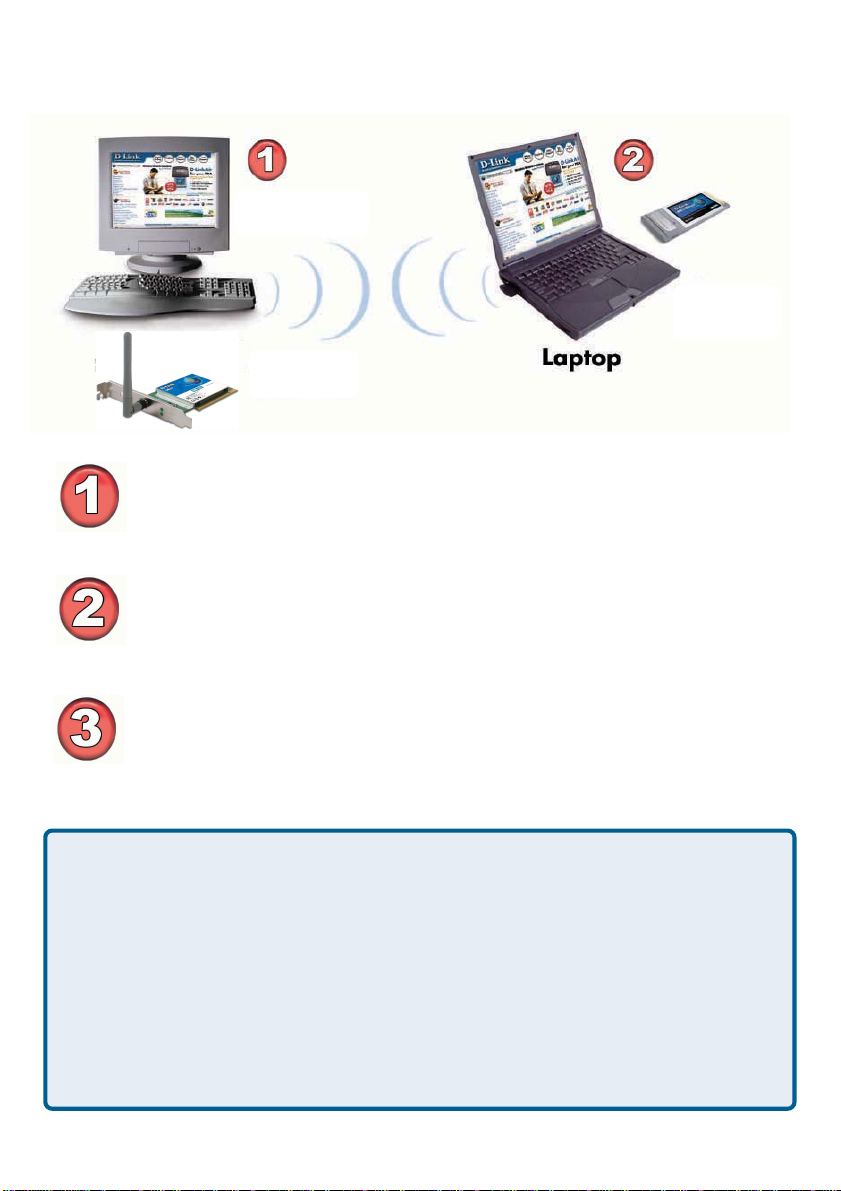
Getting Started (continued)
Setting up a Wireless Ad Hoc Network
Desktop
D-Link AirPlus Xtreme G
Install the DWA-520 into the desktop computer.
(See the Quick Installation Guide included with the product for
installation instructions.)
Install the DWL-G650 Wireless PC Card Adapter into a laptop computer .
(See the Quick Installation Guide included with the product.)
Set the wireless configuration for the adapters to Ad-Hoc mode, set the
adapters to the same channel, and assign an IP Address to each
computer on the Ad-Hoc network. (See Box below).
TM
D-Link AirPlus Xtreme G
DWL-G650
TM
IP Address
When assigning IP Addresses to the computers on the network, please remember
that the IP Address for each computer must be in the same IP Address range
as all the computers in the network, and the subnet mask must be exactly the
same for all the computers in the network.
For example: If the first computer is assigned an IP Address of 192.168.0.2 with a
Subnet Mask of 255.255.255.0, then the second computer can be assigned an IP
Address of 192.168.0.3 with a Subnet Mask of 255.255.255.0, etc.
IMPORT ANT : If computers or other devices are assigned the same IP Address,
one or more of the devices may not be visible on the network.
11
Page 12
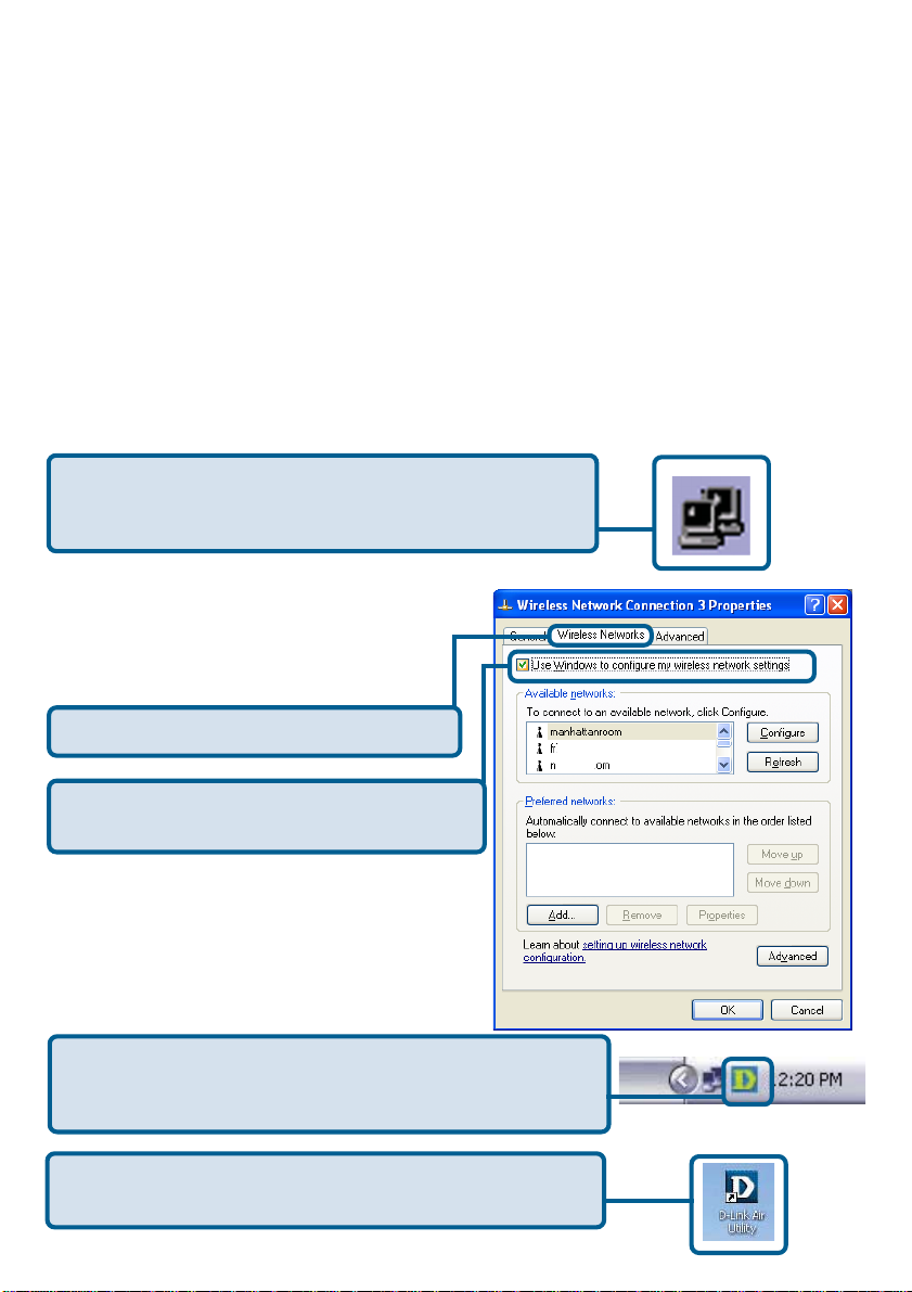
Using the Configuration Utility
D-Link DWA-520 uses the Configuration Utility as the
management software. The utility provides the user an easy interface to change any
settings related to the wireless adapter. After you have completed the inst allation of the
DWA-520 (refer to the Quick Installation Guide that came with your purchase) whenever
you start the computer , the Configuration Utility starts automatically and the system
tray icon is loaded in the toolbar (see illustration below*.) Clicking on the utility icon will
start the Configuration Utility. Another way to start the Configuration Utility is to
click on Start>Programs>D-Link AirPlus Xtreme G>D-Link AirPlus Xtreme G Utility .
If you are using Windows XP, you can use either the Zero Configuration Utility or the
D-Link Configuration Utility .
T o use the D-Link Configuration Utility with XP, right-click
on the Wireless network icon in the taskbar in the lower
right-hand corner of your computer screen.
In the window that appears, select View
Available Wireless Networks and click
the Advanced button. The screen at right
will appear.
Select the Wireless Networks tab.
TM
Uncheck the box in the properties window
that enables windows configuration.
After you have done this, you can then use the D-Link
Configuration Utility with XP by clicking on the D-Link
Configuration Utility icon.
If the icon does not display in the taskbar , then click on
this icon on your desktop to open.
*Configuration Utility icon
in the system tray
12
Page 13
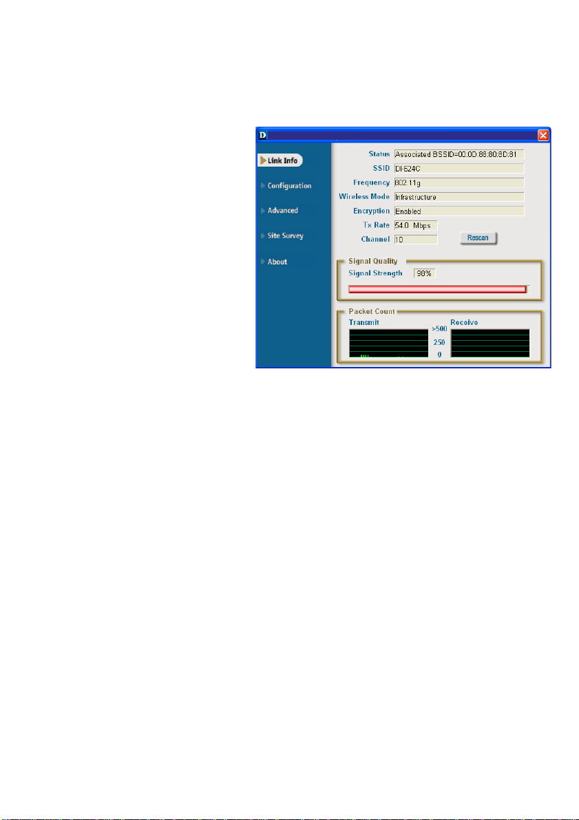
Using the Configuration Utility (continued)
After clicking on the Configuration Utility icon, the Link Info screen will display the
settings for the DWA-520:
Status:
Displays the MAC Address of the
Access Point or Router to which the
DWA-520 is associated
SSID:
The Service Set Identifier is the name
assigned to the wireless network.
The factory SSID setting is default.
Frequency:
802.11g indicates that the DWLG520 is communicating in the
2.4GHz band.
Wireless Mode:
Either Infrastructure or Ad-Hoc will be displayed here. (Please see the Getting
Started section in this manual for an explanation of these two modes.)
Encryption:
Y ou can see if WEP (Wired Equivalent Privacy) is Enabled or Disabled here.
Link Info
D-Link AirPlus Xtreme G Utility
D-Link AirPlus Xtreme G Utility
Tx Rate:
Tx Rate settings are automatically determined for an optimal speed up to a maximum
of 54Mbps.
Channel:
The channel selection is automatically determined by the DWA-520.
Signal Strength:
Displays the Link Quality for the DWA-520 wireless connection to the Access Point.
The Signal Strength represents the wireless signal between the Access Point and the
DWA-520. The percentage coincides with the graphical bar.
Packet Count:
Displays the statistics of the data packets that are transmitted and received.
Rescan Button:
Rescans for the strongest signal in your environment and associates with that Access
Point or Router.
13
Page 14
Using the Configuration Utility (continued)
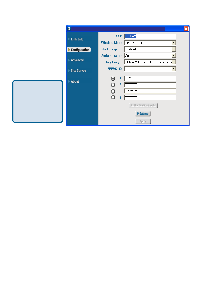
Configuration
D-Link AirPlus Xtreme G Utility
After you have configured
the network through the
Site Survey section of
the D-Link AirPlus Utility ,
you can make minor
adjustments and check
on settings in this
Configuration screen.
For a complete
explanation of the
configuration of a
network, please refer
to the Site Survey
section in this
chapter.
SSID:
Service Set Identifier is a name that identifies a wireless network. Access Points and
wireless devices attempting to connect to a specific WLAN (Wireless Local Area Network)
must use the same SSID. The default setting is default.
Wireless Mode:
Click on the pull-down menu; select from the following options:
Infrastructure - connecting to the WLAN using an Access Point. (This is the default
setting).
Ad-Hoc – wireless mode used when connecting directly to a computer equipped
with a wireless adapter in a peer-to-peer environment.
Data Encryption:
Select Enabled or Disabled.
Authentication:
Choose one of the following modes:
Open Authentication – the DWA-520 is visible to all devices on the network
Shared Authentication – allows communication only with other devices with
identical WEP settings
WPA/WPA2 – Wi-Fi Protected Access which authorizes and identifies users
based on a secret key that changes automatically at a regular interval.(A RADIUS
Server is required for this mode.)
WPA/WPA2-PSK - WPA/WPA2 Pre-Shared Key mode ensures that the DWL
G520 will obtain a new security key every time it connects to the 802.11 network.
(A RADIUS Server is not required for this mode.)
14
Page 15
Using the Configuration Utility (continued)
Key Length:
Select the key length and either ASCII or hexadecimal format.
IEEE 802.1x:
Authentication which is a first line of defense against intrusion. In the Authentication
process the Authentication Server* verifies the identity of the client attempting to connect to the network. Unfamiliar clients are denied access.
Keys 1-4:
Select the default key
Hexadecimal digits consist of the numbers 0-9 and the letters A-F
ASCII (American Standard Code for Information Interchange) is a code for
representing English letters as numbers from 0-127
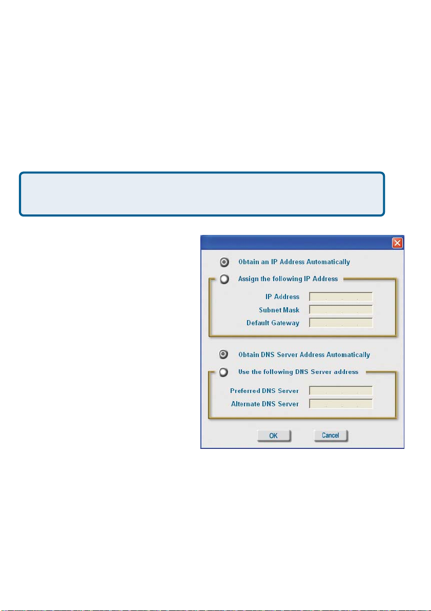
IP Settings
When you click IP Settings in the
Configuration window, this pop-up
screen will appear. Configure the IP
Settings in this window.
Click Apply to save changes.
*Not all servers can provide Authentication
15
Page 16
Using the Configuration Utility (continued)
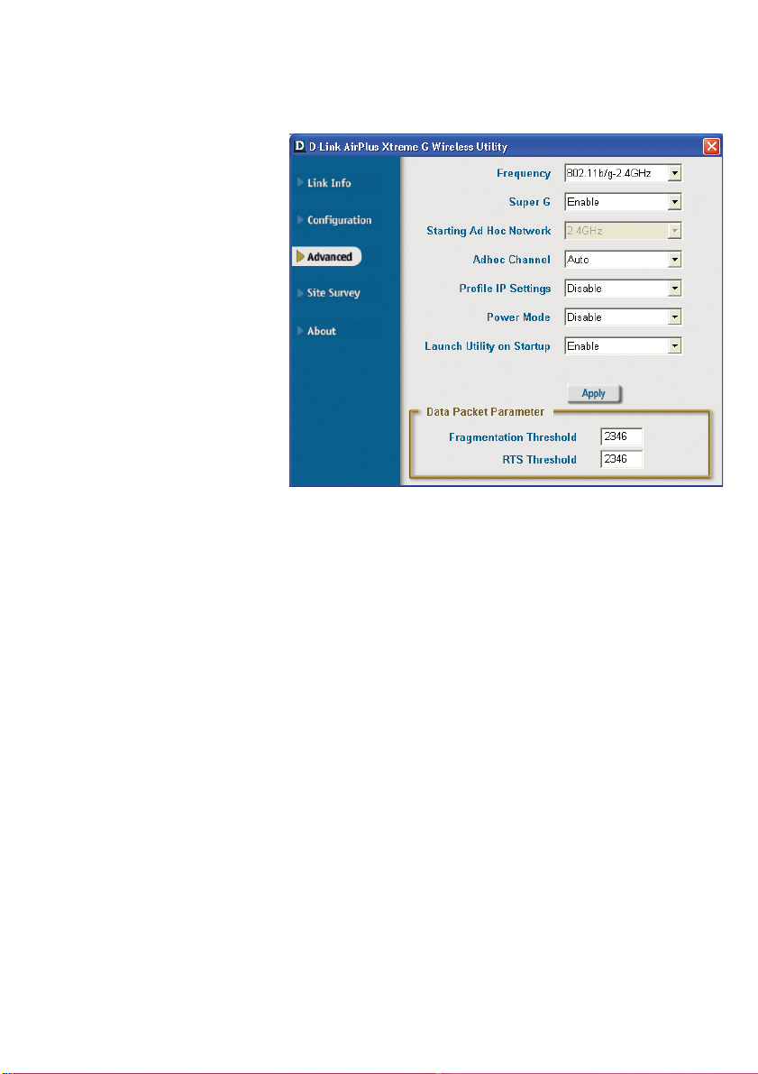
Frequency:
Select 802.1 1b/g - 2.4GHz or
802.1 1b.
Advanced
Super G:
Enable or Disable the Super G
function (108Mbps). In order to
communicate, all devices must
share the same setting for this
feature.
Starting Ad-Hoc Network:
This setting is always 2.4GHz.
Ad-Hoc Channel:
All devices in the Ad-Hoc network must be set to the same
channel.
Profile IP Settings:
You can Enable or Disable the IP Settings portion of your profile here. If you select
Disable you will need to configure the IP address information each time you connect to
a network. If you select Enable you will maintain the same IP address information each
time you connect to a network.
Power Mode:
Disable -This default setting consumes the most power .
Enable - This setting consumes the least power .
Launch Utility on Startup:
Select Enable or Disable.
Data Packet Parameter:
Set the Fragmentation Threshold and the RTS Threshold. Please see below .
Fragmentation Threshold:
This value should remain at its default setting of 2432. If you experience a high packet
error rate, you may slightly increase your Fragmentation Threshold within the value
range of 256 to 2432. Setting the Fragmentation Threshold too low may result in poor
performance.
RTS Threshold:
This value should remain at its default setting of 2432. If inconsistent data flow is a
problem, only a minor modification should be made.
Click Apply if you have made any changes.
16
Page 17
Using the Configuration Utility (continued)
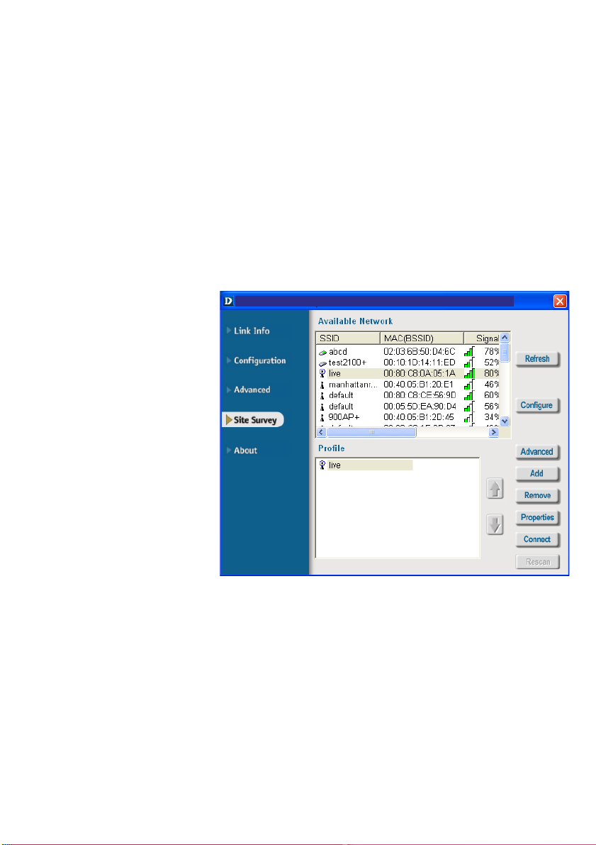
Available Network:
The top section of the window displays the Available Networks. Scroll up and down the
list and highlight the network to which you wish to connect. Click on the Connect button.
Profile:
In the lower half of the screen, you can manage the profiles that you have created for the
wireless network at home, at the office and in public places. Scroll up and down and
highlight the profile that you wish to configure. You can Add or Remove a profile, or
configure the Properties of the profile in order to connect with an available network.
Refresh:
Click on Refresh to get the
most updated list of available
networks.
Site Survey
D-Link AirPlus Xtreme G Utility
Configure:
Highlight an existing network
and click Configure; the
configuration window on the
next page will appear .
Advanced:
Highlight a network; click
Advanced and the screen on
the next page will appear.
Add:
Click Add and the screen on the next page will appear.
Remove:
Highlight a network profile; click Remove to remove a network from the profile list.
Properties:
Highlight a network profile; click Properties and the screen on the next p age will appear.
Connect:
Highlight a network profile; click Connect to connect to that network.
Rescan:
Click Rescan to rescan and connect to the strongest signal.
17
Page 18
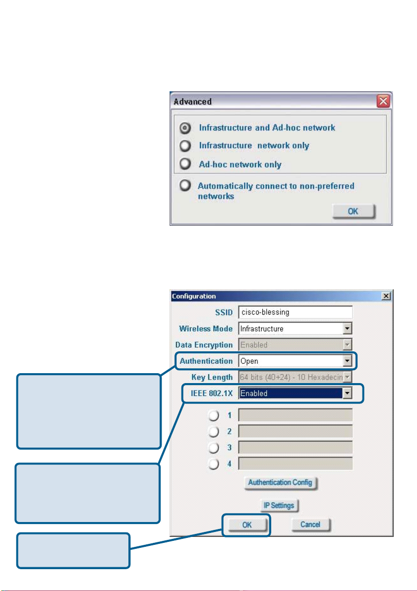
Using the Configuration Utility (continued)
Site Survey > Add
Advanced
In this window you can select
the type of network connection.
Click OK to save the
changes.
If you clicked on Add, you can
configure, in this window, all the
properties of a profile that you
wish to add to the network.
If you clicked on Configuration
or Properties you can configure, in this window, all the properties of a profile that already
exists in the network.
Configuration, Add or Properties
If you select WPA/WPA2 in the
Authentication field, please
see detailed instructions for
configuring WPA/WPA2 on the
following pages.
If you choose to use the IEEE
802.1x feature, please see the
detailed instructions on the following pages.
Click OK to save the
changes.
18
Page 19
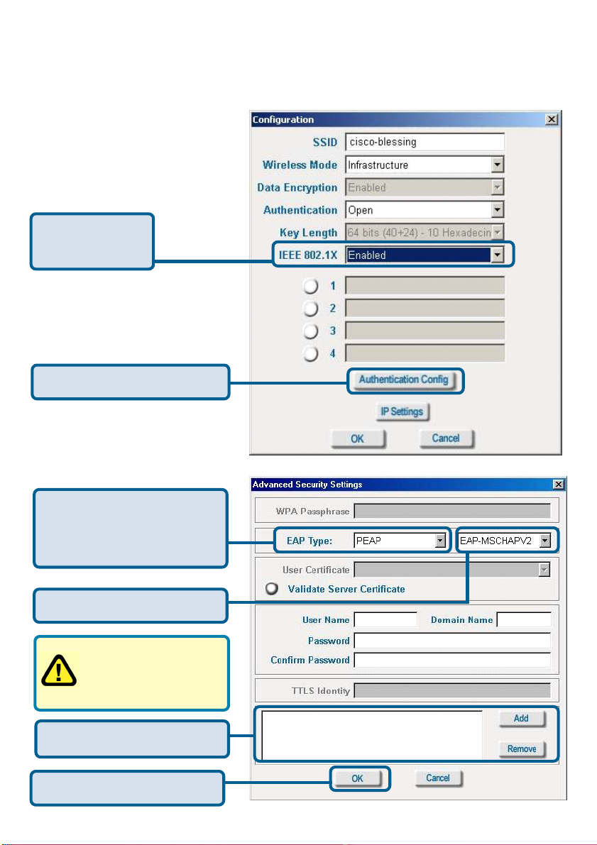
Using the Configuration Utility (continued)
Site Survey > Configuration > 802.1x
T o use 802.1x and to configure it s settings, please do the following:
IEEE 802.1x -
Select Enabled.
Click Authentication Config.
Advanced Security Settings
Select the EAP Type you
want to use. Configure the
information needed for
authenticating.
Inner Authentication Protocol.
For an explanation of
the terms shown in this
window please see the
following pages.
Trusted CA List.
Click OK
19
Page 20
Using the Configuration Utility (continued)
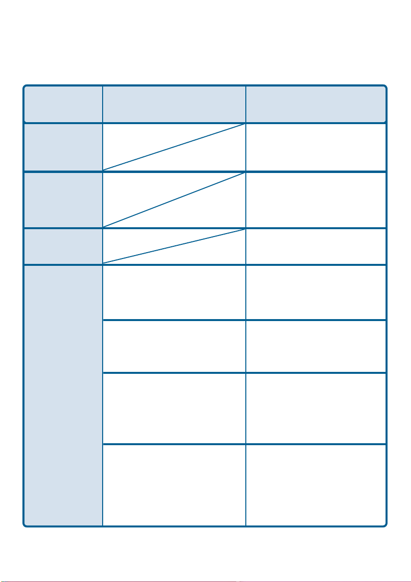
802.1x > Advanced Security Settings > EAP Types
EAP Type
EAP-TLS
EAPMSCHAPv2
LEAP
EAP-TTLS
Inner Authentication
Protocol
PAP
CHAP
Information needed
for Authenticating
Certificate
User Name
User Name
Password
Domain Name
User Name
Password
TTLS Identity
User Name
Password
TTLS Identity
User Name
Password
MSCHAP
MSCHAPv2
TTLS Identity
User Name
Password
Domain Name
TTLS Identity
User Name
Password
Domain Name
20
Page 21

Using the Configuration Utility (continued)
802.1x > Advanced Security Settings > EAP Types (continued)
EAP Type
EAP-TTLS
PEAP
Inner Authentication
Protocol
EAP-MD5
EAPGeneric T oken card
EAP-MSCHAPv2
EAP-MD5
EAP-MSCHAPv2
Information needed
for Authenticating
TTLS Identity
User Name
Password
TTLS Identity
User Name
Password
TTLS Identity
User Name
Password
Domain Name
User Name
Password
User Name
Password
Domain Name
EAPGeneric T oken card
802.1x > Advanced Security Settings > Definitions of Terms
Validate Server Certificate:
Check V alidate Server Certificate to verify the identity of the authentication server
based on its certificate when using EAP-TTLS, PEAP, and EAP-TLS. (This is
checked by default.)
Certain protocols, such as EAP-TTLS, PEAP, and EAP-TLS, allow you to verify the
identity of the authentication server as the server verifies your identity . This is called
mutual authentication.
Y ou can select trusted authentication server certificates using the Add button at the
Trusted CA List (at the bottom of the Advanced Security Settings page).
User Name
Password
21
Page 22
Using the Configuration Utility (continued)
802.1x > Advanced Security Settings > Definitions of Terms (continued)
Domain Name:
Each server has a domain name that uniquely identifies it. That domain name is normally
contained in the Subject CN field of the server certificate. A server domain name ends
with the name of a larger administrative domain, to which the server belongs.
TTLS Identity:
Tunneled Transport Layer Security satisfies a requirement for strong encryption and
mutual authentication on Wireless networks. EAP-TTLS has a unique feature that other
protocols do not offer . Because it sets up an encrypted tunnel for your credentials, it is
also able to pass your login name through that tunnel. That means that not only are your
credentials secure from eavesdropping, but your identity is protected as well. Thus, with
EAP-TTLS you have two identities: an inner one, and an outer one. The inner identity is
your actual user name. Your outer identity can be completely anonymous. Set your
outer identity in the TTLS Identity field.
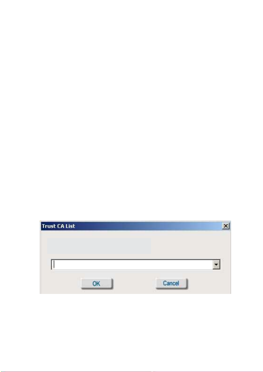
Trusted CA List:
The Trusted CA List allows you to configure which authentication servers you trust for
the purpose of logging you in to the network.
Click Add at the Trusted CA List at the bottom of the Advanced Security Settings page.
Select the T rusted CA that you want to add and click OK.
Select the Trust CA:
22
Page 23

Using the Configuration Utility (continued)
Authentication > WPA/WPA2
D-Link AirPlus Xtreme G Utility
Select the available
network to which you
want to connect.
Click Configure.
Select WPA/WPA2 in
the Authentication field.
Click Authentication
Config
After you click Authentication Config, the Advanced Security Settings screen will ap-
pear. Complete the Advanced Security Settings configuration. Please see pages 19-22 of
this manual to find out more about the Advanced Security Settings.
23
Page 24
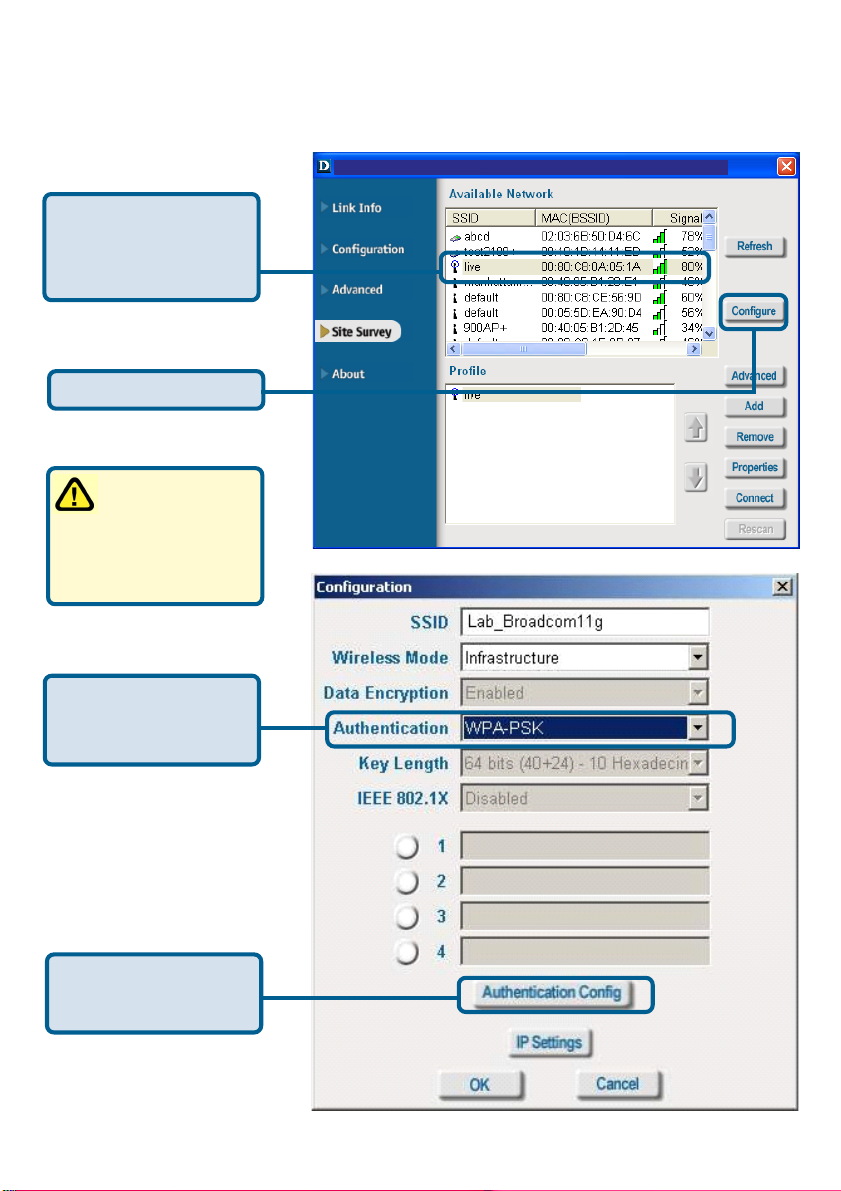
Using the Configuration Utility (continued)
Authentication > WPA/WPA2-PSK
D-Link AirPlus Xtreme G Utility
Select the available
network to which you
want to connect.
Click Configure.
WPA/WPA2-PSK does
require a RADIUS
Server in the network.
Select WPA/WPA2-
PSK in the Authentica-
tion field.
Click Authentication
Config
24
Page 25
Using the Configuration Utility (continued)
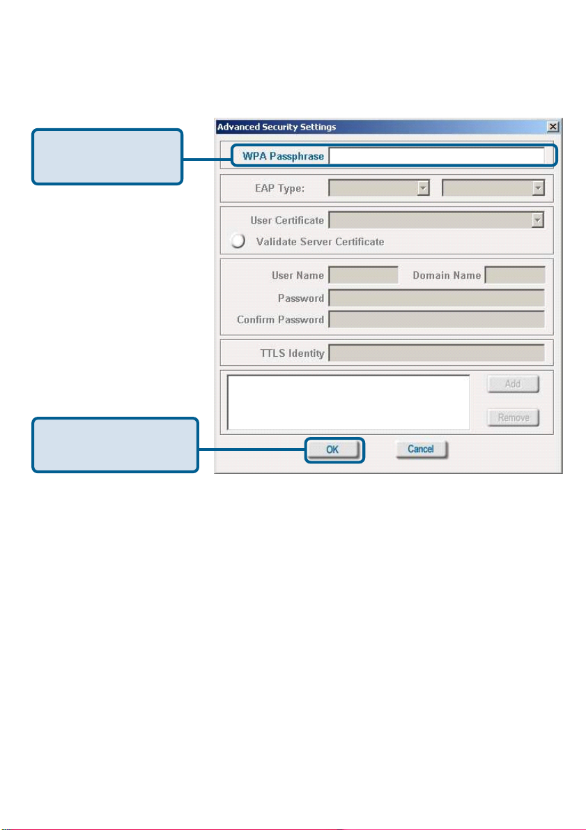
Authentication > WPA/WPA2-PSK (continued)
Advanced Security Settings
Enter the WPA/WPA2
Passphrase.
Click OK.
The configuration is done.
25
Page 26
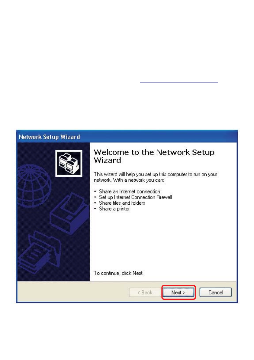
Networking Basics
Using the Network Setup Wizard in Windows XP
In this section you will learn how to establish a network at home or work, using
Microsoft Windows XP.
Note: Please refer to websites such as
and http://www.microsoft.com/windows2000 for information about networking
computers using Windows 2000, ME or 98SE.
Go to Start>Control Panel>Network Connections
Select Set up a home or small office network
http://www.homenethelp.com
When this screen appears, click Next.
26
Page 27
Networking Basics (continued)
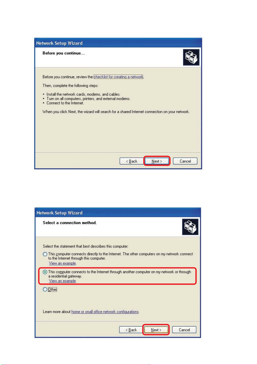
Please follow all the instructions in this window:
Click Next
In the following window, select the best description of your computer . If your
computer connects to the Internet through a gateway/router, select the second option
as shown.
Click Next
27
Page 28
Networking Basics (continued)
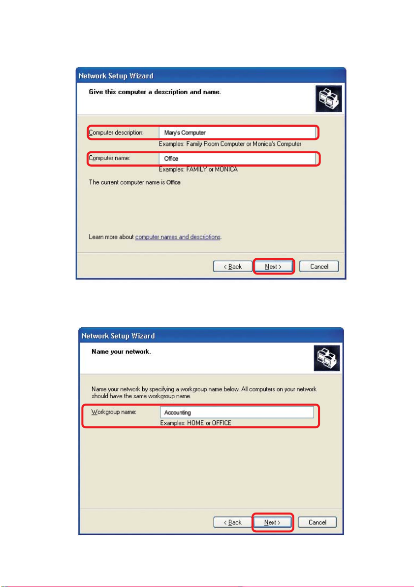
Enter a Computer description and a Computer name (optional.)
Click Next
Enter a Workgroup name. All computers on your network should have the same
Workgroup name.
Click Next
28
Page 29
Networking Basics (continued)
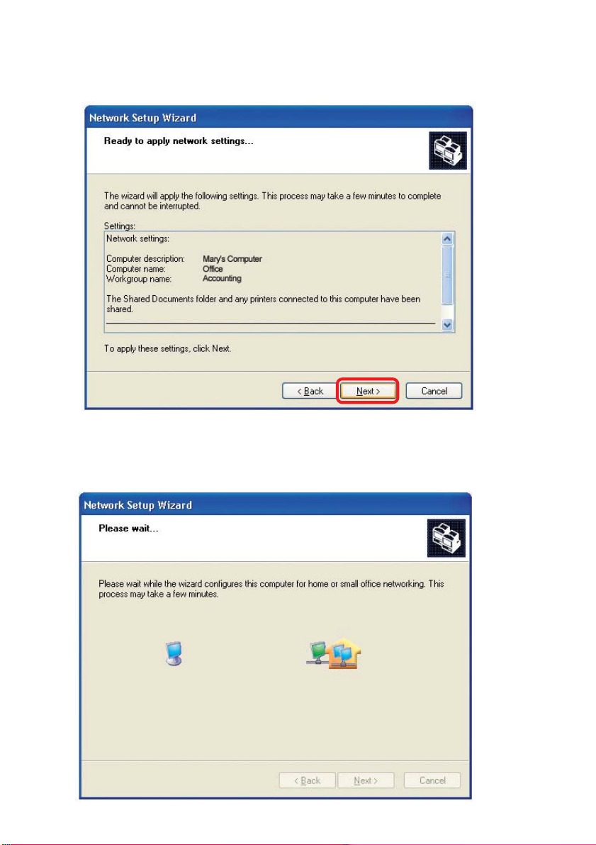
Please wait while the Network Setup Wizard applies the changes.
When the changes are complete, click Next.
Please wait while the Network Setup Wizard configures the computer.
This may take a few minutes.
29
Page 30
Networking Basics (continued)
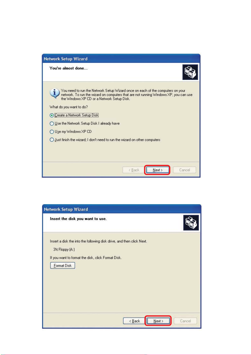
In the window below, select the option that fit s your needs. In this example, Create a
Network Setup Disk has been selected. You will run this disk on each of the
computers on your network. Click Next.
Insert a disk into the Floppy Disk Drive, in this case drive A.
30
Page 31
Networking Basics (continued)
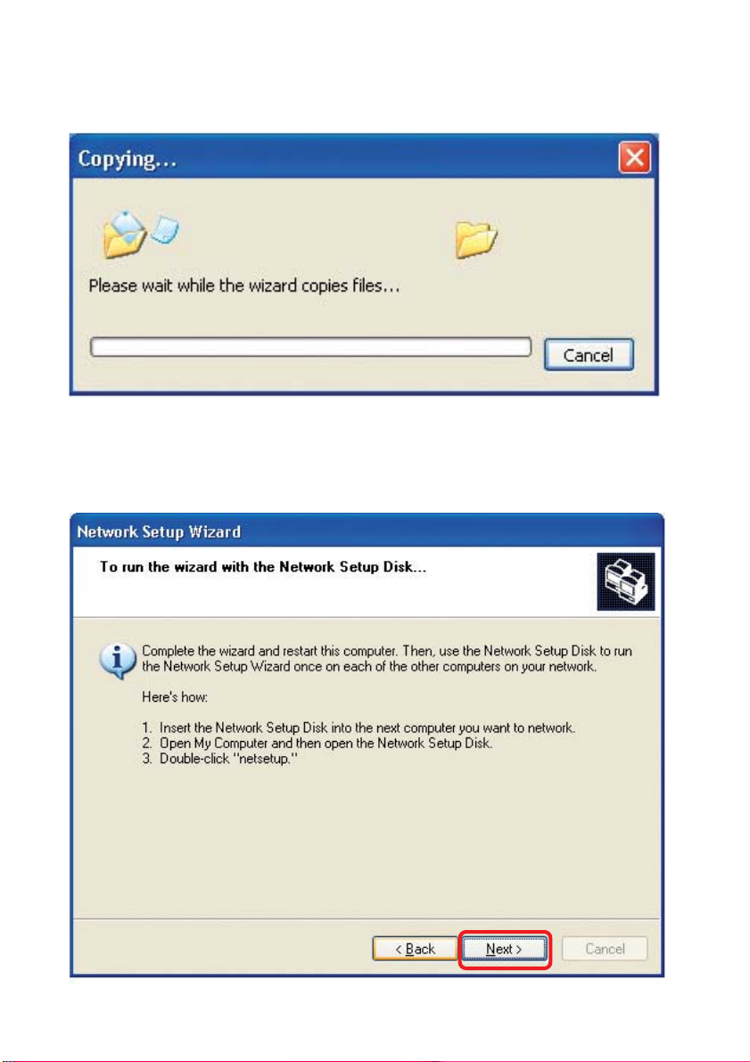
Please read the information under Here’s how in the screen below . After you complete
the Network Setup Wizard you will use the Network Setup Disk to run the Network
Setup Wizard once on each of the computers on your network. T o continue click Next.
31
Page 32
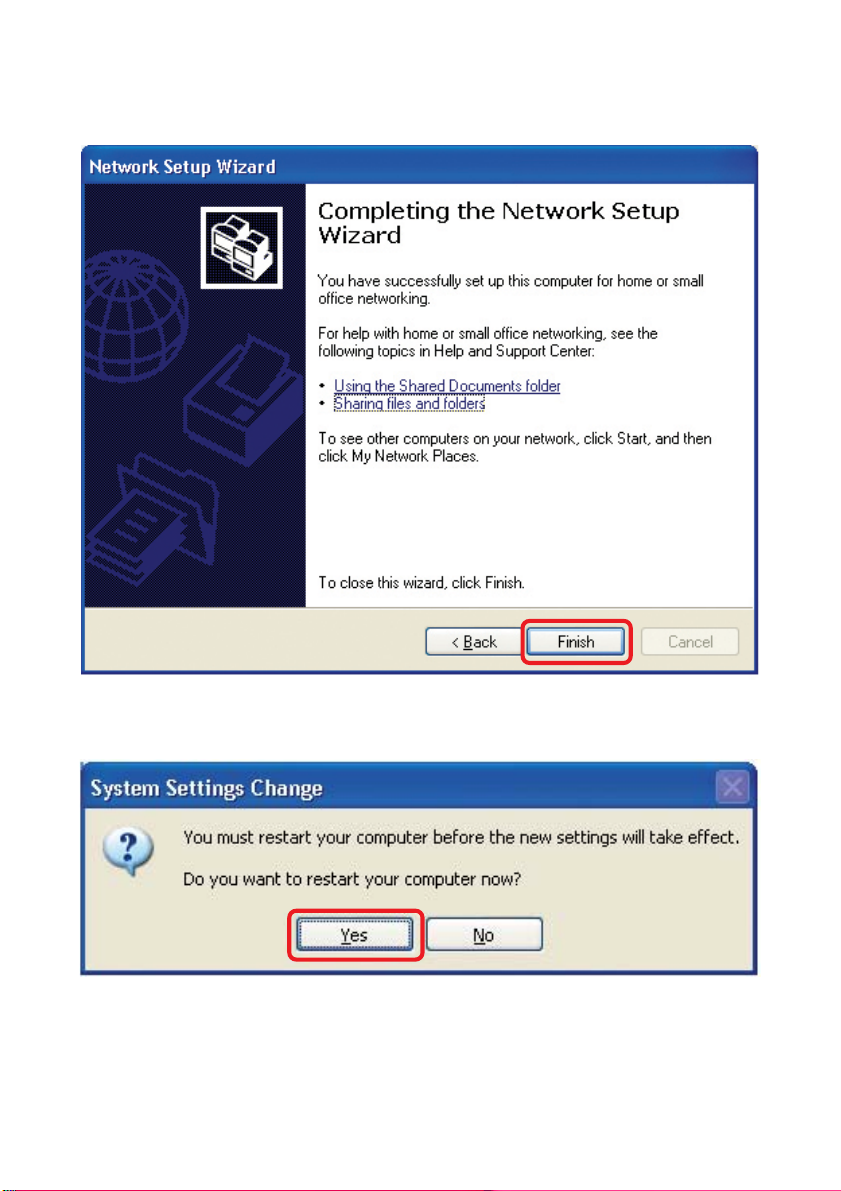
Networking Basics (continued)
Please read the information on this screen, then click Finish to complete the
Network Setup Wizard.
The new settings will take effect when you restart the computer . Click Yes to restart
the computer.
Y ou have completed configuring this computer . Next, you will need to run the Network
Setup Disk on all the other computers on your network. After running the Network
Setup Disk on all your computers, your new wireless network will be ready to use.
32
Page 33
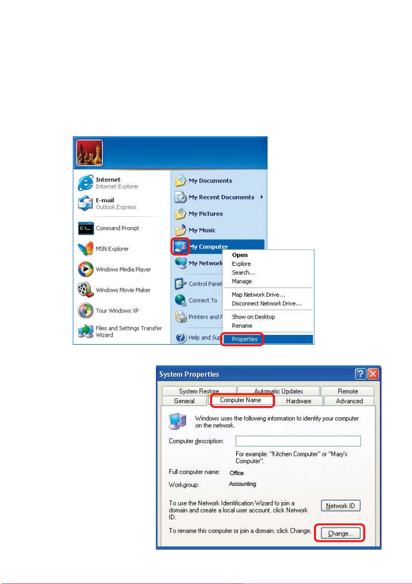
Networking Basics (continued)
Naming your Computer
T o name your computer , please follow these directions:In Windows XP:
Click Start (in the lower left corner of the screen)
!
Right-click on My Computer
!
Select Properties and click
!
Select the Computer
!
Name Tab in the System
Properties window.
!
You may enter a Computer Description if you
wish; this field is optional.
To rename the computer
!
and join a domain, Click
Change.
33
Page 34
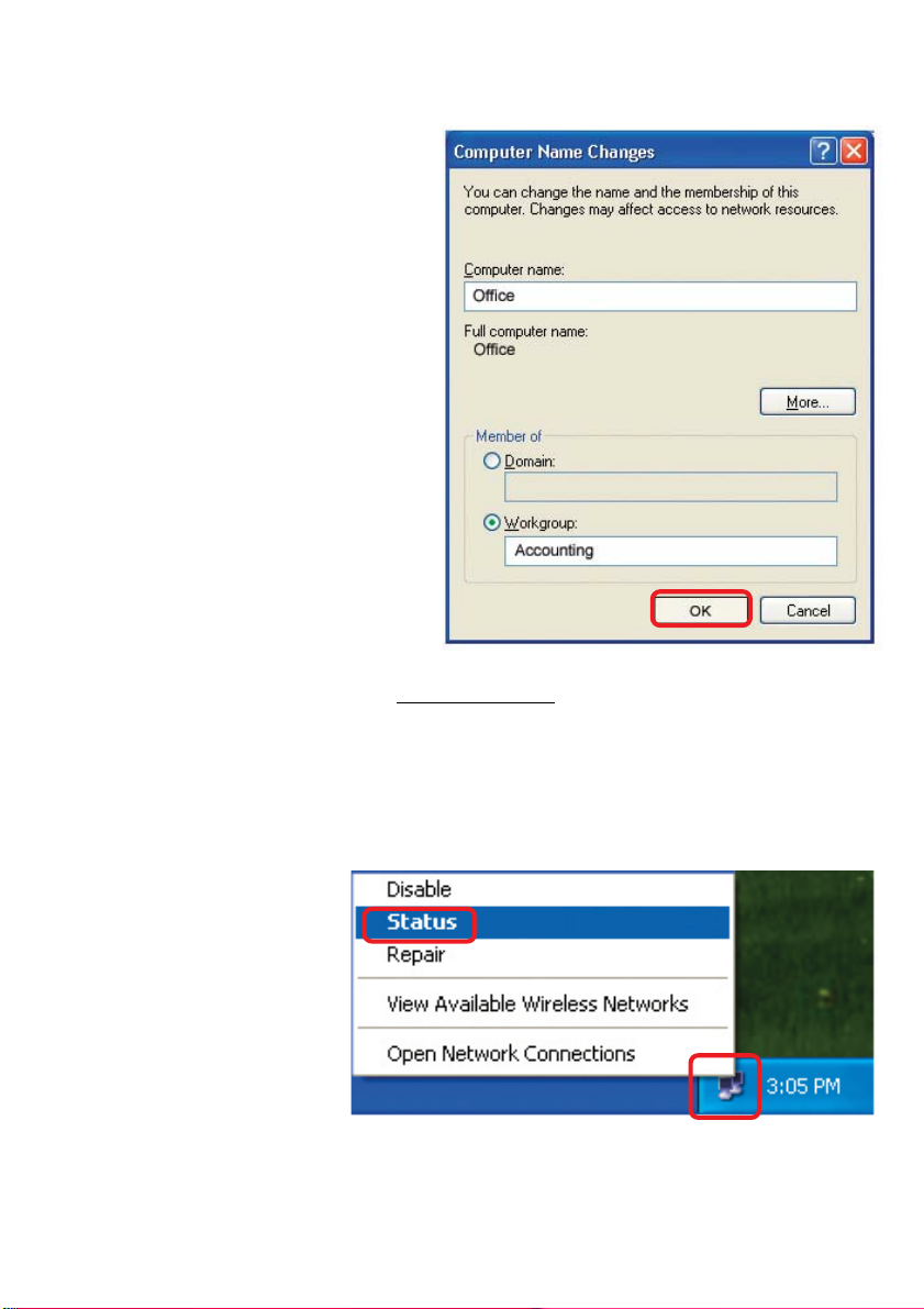
Networking Basics (continued)
Naming your Computer
!
In this window, enter the
Computer name
Select Workgroup and enter
!
the name of the Workgroup
All computers on your network
!
must have the same
Workgroup name.
Click OK
!
Checking the IP Address in Windows XP
The wireless adapter-equipped computers in your network must be in the same IP
Address range (see Getting Started in this manual for a definition of IP Address Range.)
To check on the IP Address of the adapter, please do the following:
Right-click on the
!
Local Area
Connection icon
in the task bar
Click on Status
!
34
Page 35
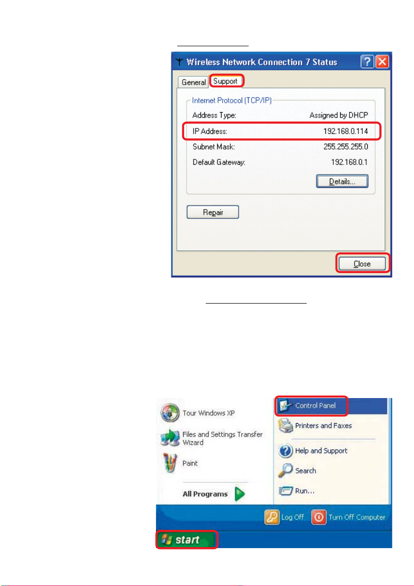
Networking Basics (continued)
Checking the IP Address in
This window will appear.
Click the
!
Support tab
Click Close
!
Windows XP
Assigning a Static IP Address in Windows XP/2000
Note: Residential Gateways/Broadband Routers will automatically assign IP Addresses to the computers on the network, using DHCP (Dynamic Host Configuration Protocol) technology. If you are using a DHCP-capable Gateway/Router you
will not need to assign Static IP Addresses.
If you are not using a DHCP capable Gateway/Router , or you need to assign a S tatic IP
Address, please follow these instructions:
Go to Start
!
Double-click on
!
Control Panel
35
Page 36
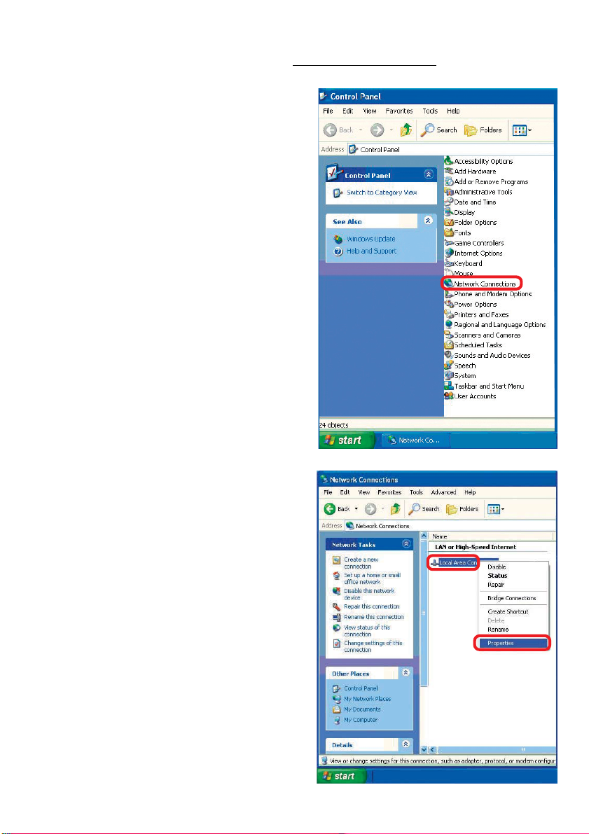
Networking Basics (continued)
Assigning a Static IP Address in
Double-click on
!
Network
Connections
Windows XP/2000
Right-click on Local Area
!
Connections
Double-click on
!
Properties
36
Page 37
Networking Basics (continued)
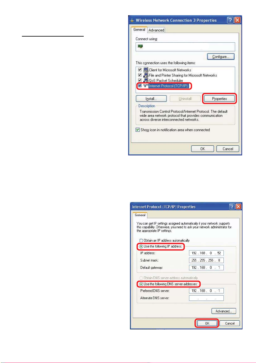
Assigning a Static IP Address
in Windows XP/2000
Click on Internet Protocol
!
(TCP/IP)
Click Properties
!
In the window below, select Use the following IP Address. Input your IP
!
!
Address and subnet mask. (The IP Addresses on your network must be
within the same range. For example, if one computer has an IP Address of
192.168.0.2, the other computers should have IP Addresses that are
sequential, like 192.168.0.3 and 192.168.0.4. The subnet mask must be the
same for all the computers on the network.)
IP Address:
e.g., 192.168.0.2
D-Link Air DWL-520 Wireless PCIAdapter
Subnet Mask:
255.255.255.0
Default Gateway:
Enter the LAN IP Address of
the wireless router. (D-Link
wireless routers have a LAN IP
Address of 192.168.0.1)
Select Use the following
!
DNS server address. Enter
the LAN IP Address of the
wireless router. (D-Link
wireless routers have a LAN
IP Address of 192.168.0.1)
Click OK
!
You have completed the assignment of a S tatic IP Address. (Y ou do not need to assign
a Static IP Address if you have a DHCP-capable Gateway/Router.)
37
Page 38
Networking Basics (continued)
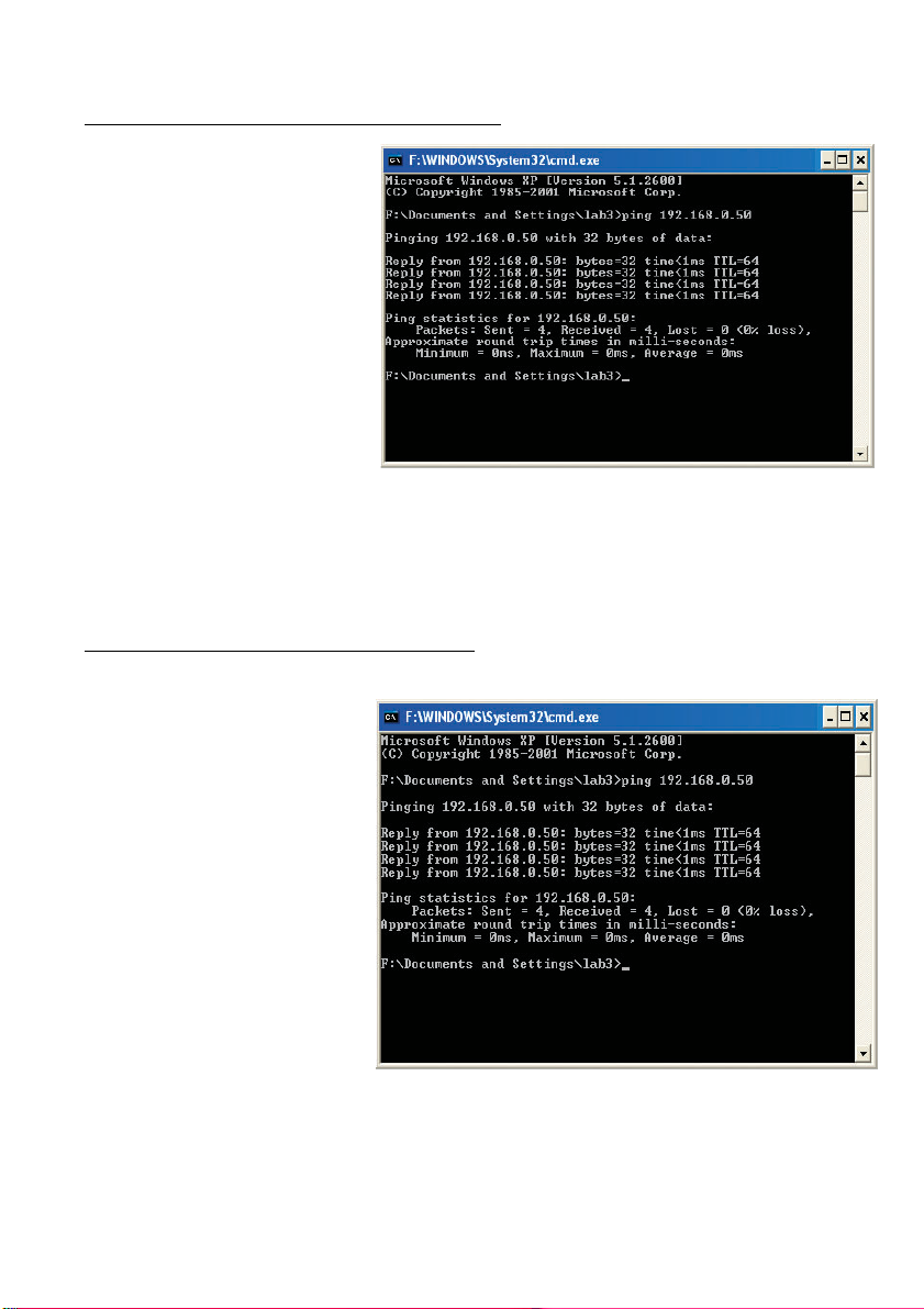
Checking the Wireless Connection
Pinging in Windows XP and 2000*
by
Go to Start > Run >
!
type cmd. A window
similar to this one
will appear. Type
ping
xxx.xxx.xxx.xxx,
where xxx is the IP
Address of the
Wireless Router or
Access Point. A
good wireless
connection will show
four replies from the
Wireless Router or
Access Point, as
shown.
Checking the Wireless Connection
by
Pinging in Windows Me and 98*
Go to Start > Run
!
> type command.
A window similar to
this will appear.
Type ping
xxx.xxx.xxx.xxx
where xxx is the IP
Address of the
Wireless Router or
Access Point. A
good wireless
connection will
show four replies
from the wireless
router or access
point, as shown.
*You may be pinging different IP Addresses than the ones pictured here, however the
procedure for pinging remains the same.)
38
Page 39
Troubleshooting
This chapter provides solutions to problems that can occur during the installation and
operation of the DWA-520. Read the following descriptions if you are having problems.
(The examples below are illustrated in Windows XP . If you have another operating system, these solutions will still apply although the appearance on your computer screen
may differ .)
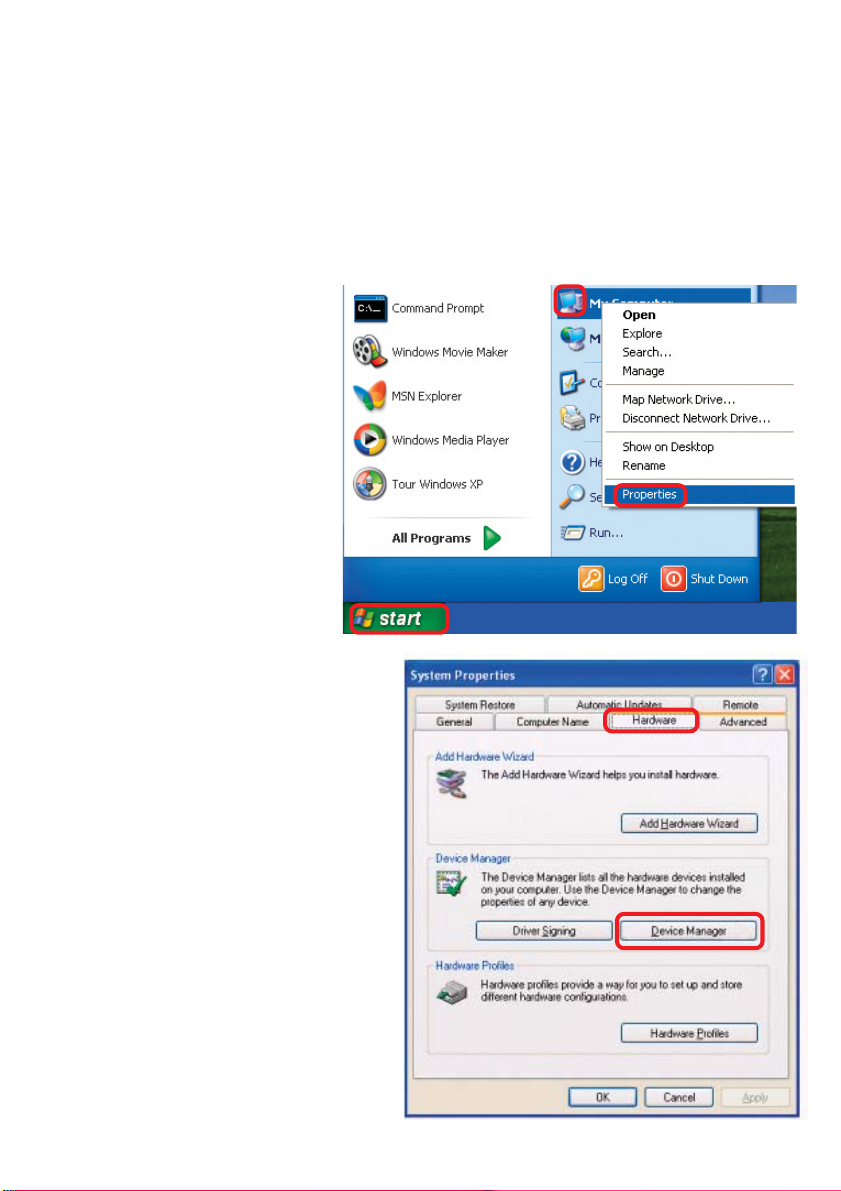
1. Check that the drivers for the DWA-520 are installed properly.
Go to Start > My
!
Computer >
Properties
Select the
!
Hardware
Tab
Click Device
!
Manager
39
Page 40
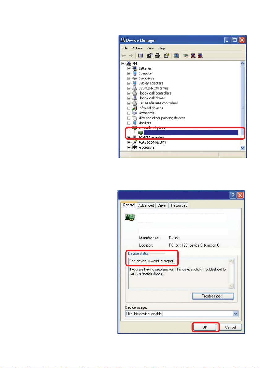
Troubleshooting (continued)
Double-click
!
on Network
Adapters
Right-click on D-Link Air
!
Plus Xtreme G DWLG520 Wireless PCI
Adapter
Select Properties
!
to check that the
drivers are
installed properly
TM
D-Link AirPlus Xtreme G DWA-520
Look under Device
!
Status to check that the
device is working
properly
Click OK
!
D-Link AirPlus Xtreme G DWA-520 Wireless PCI Adapter
D-Link AirPlus Xtreme G Wireless PCI Adapter
D-Link AirPlus Xtreme G Wireless PCI Adapter
40
Page 41

Troubleshooting (continued)
2. I cannot connect to the Access Point or the Wireless Router.
Make sure that the SSID on the DWA-520 Wireless PCI Adapter is
!
exactly the same as the SSID on the Access Point or Wireless Router.
Move the DWA-520 and Access Point or Wireless Router into the
!
same room and then test the wireless connection.
Disable all security settings. (WEP, MAC Address Control, AES)
!
Turn off your Access Point and the computer with the DWA-520. Turn
!
on the Access Point, and then turn on the computer with the DWA-520.
Refresh the DWA-520 Utility
!
3. The DWA-520 Power and Link lights are not on.
Check to see if the DWA-520 PCI adapter is firmly inserted into the PCI
!
slot of your computer.
4. I forgot my Encryption key .
Reset the Access Point to its factory default settings and restore the DWL-
!
G520 Wireless PCI Adapter to the factory default settings. (The default settings
are listed in the Using the Configuration Utility section in this manual.)
5. The computer does not recognize the DWA-520 Wireless PCI Adapter.
Make sure that the DWA-520 Wireless PCI Adapter is properly seated in
!
the computer’s PCI slot.
If Windows does not detect the hardware upon insertion of the adapter,
!
make sure to completely remove drivers that were previously loaded. To
remove the drivers, do the following:
41
Page 42

Troubleshooting (continued)
A. Under Tools> select Folder Options…> select View > under
Hidden files and folders > select Show hidden files and
folders
B. Uncheck Hide extension for known file types > click on
Apply
C. Search for the files DWLG520.INF and DWLG520.SYS.
Remove these files from the INF and SYSTEM32 (DRIVERS)
folders in the Windows directory. Note: Windows XP and
Windows 2000 will rename .inf files that have not received
WHQL certification into oem.inf files (e.g., oem1.inf.)
6. The computer with the DWA-520 installed is unable to connect to
the wireless network and/or the Internet.
Check that the LED indicators for the broadband modem are indicating
!
normal activity . If not, there may be a problem with the broadband connection.
Check that the LED indicators on the wireless router are functioning properly .
!
If not, check that the AC power and Ethernet cables are firmly connected.
Check that the IP Address, subnet mask, gateway, and DNS settings are
!
correctly entered for the network
In Infrastructure mode, make sure the same Service Set Identifier (SSID)
!
is specified on the settings for the wireless clients and Access Point s. The
SSID factory default setting for the D-LinkAir and AirPlus products is default.
(Double-click on the WLAN icon in the taskbar. The Link Info screen will
display the SSID setting.)
In Ad-Hoc mode, both wireless clients will need to have the same SSID.
!
Please note that it might be necessary to set up one client to establish a
BSS (Basic Service Set) and wait briefly before setting up other clients.
This prevents several clients from trying to establish a BSS at the same
time, which can result in multiple singular BSSs being established, rather
than a single BSS with multiple clients associated to it.
42
Page 43

Troubleshooting (continued)
Check that the Network Connection for the wireless client is configured
!
properly . Select AP (Infrastructure) when connecting to an Access Point
and select Ad-Hoc mode when connecting without an Access Point.
Double-click on the WLAN icon in the taskbar > click on Configuration to
change the settings for the wireless adapter.
!
If Security is enabled, make sure that the correct encryption keys are
entered on both the DWA-520 and the Access Point. Double-click on the
WLAN icon in the taskbar > click Encryption. Check to see that the key
selected is set to the same key as other devices on the network.
7. How can I troubleshoot distance issues using the DWA-520.
Move the DWA-520 and Access Point or Wireless Router into the same
!
room and then test the wireless connection.
Change the channel of the Access Point.
!
Move devices within the line of sight
!
43
Page 44

Technical Specifications
Standards
IEEE 802.1 1g
!
!
IEEE 802.1 1
IEEE 802.1 1b
!
Bus Type:
PCI 2.2
!
Data Rates:
With Automatic Fallback
54Mbps; 48Mbps; 36Mbps; 24Mbps; 18Mbps; 12Mbps; 11Mbps;
!
9Mbps; 6Mbps; 5.5Mbps; 2Mbps; 1Mbps;108Mbps
Security:
802.1x
!
WPA/WPA2 (Wi-Fi Protected Access ), 64-,128-bit WEP with TKIP,
!
MIC, IV Expansion, Shared Key Authentication
Media Access Control:
!
CSMA/CA with ACK
Frequency Range:
2.4GHz ~ 2.4835GHz
!
Range:*
Indoors: Up to 328 feet (100 meters)
!
Outdoors: Up to 1,312 feet (400 meters)
!
Power Consumption:
PowerSave mode = 28mA
!
St andby mode = 4.66mA
!
Transmit mode = 248mA
!
Modulation Technology:
Orthogonal Frequency Division Multiplexing (OFDM)
!
*Environmental factors may adversely affect range
44
Page 45

T echnical Specifications
Receiver Sensitivity:
54Mbps OFDM, 10% PER,-68dBm
!
48Mbps OFDM, 10% PER,-68dBm
!
36Mbps OFDM, 10% PER,-75dBm
!
24Mbps OFDM, 10% PER,-79dBm
!
18Mbps OFDM, 10% PER,-82dBm
!
12Mbps OFDM, 10% PER,-84dBm
!
11Mbps CCK, 8% PER, -82dBm
!
9Mbps OFDM, 10% PER,-87dBm
!
6Mbps OFDM, 10% PER,-88dBm
!
5.5Mbps CCK, 8% PER,-85dBm
!
2Mbps QPSK, 8% PER,-86dBm
!
1Mbps BPSK, 8% PER,-89dBm
!
Transmitter Output Power:
15dBm ± 2dB
!
Internal Antenna Type:
Dipole with detachable reverse SMA connector
!
Temperature
Operating: 0ºC to 55ºC (32ºF to 149ºF)
!
Humidity:
95% maximum, non-condensing
!
Physical Dimensions:
L = 4.64 inches (114.3mm)
!
W = 2.13 inches (54mm)
!
H = 0.34 inches (8.7mm)
!
Weight:
0.12 lb. (55 grams)
!
Certifications:
FCC:FCC Part 15B/C/MPE Taiwan: LP0002
!
Warranty:
3 years
!
45
Page 46

T echnical Support
Y ou can find software updates and user documentation on the D-Link website.
D-Link provides free technical support for customers within the United St ates and
within Canada for the duration of the warranty period on this product.
U.S. and Canadian customers can contact D-Link technical support through our
website, or by phone.
Tech Support for customers within the United States:
D-Link Technical Support over the Telephone:
(877) 453-5465
24 hours a day, seven days a week.
D-Link Technical Support over the Internet:
http://support.dlink.com
email:[email protected]
Tech Support for customers within Canada:
D-Link Technical Support over the Telephone:
(800) 361-5265
Monday to Friday 8:30am to 9:00pm EST
D-Link Technical Support over the Internet:
http://support.dlink.ca
email:[email protected]
46
Page 47

Federal Communication Commission Interference Statement
This equipment has been tested and found to comply with the limits for a Class B
digital device, pursuant to Part 15 of the FCC Rules. These limits are designed to
provide reasonable protection against harmful interference in a residential
installation. This equipment generates, uses and can radiate radio frequency
energy and, if not installed and used in accordance with the instructions, may cause
harmful interference to radio communications. However, there is no guarantee that
interference will not occur in a particular installation. If this equipment does cause
harmful interference to radio or television reception, which can be determined by
turning the equipment off and on, the user is encouraged to try to correct the
interference by one of the following measures:
- Reorient or relocate the receiving antenna.
- Increase the separation between the equipment and receiver.
- Connect the equipment into an outlet on a circuit different from that
to which the receiver is connected.
- Consult the dealer or an experienced radio/TV technician for help.
This device complies with Part 15 of the FCC Rules. Operation is subject to the
following two conditions: (1) This device may not cause harmful interference, and (2)
this device must accept any interference received, including interference that may
cause undesired operation.
FCC Caution: Any changes or modifications not expressly approved by the party
responsible for compliance could void the user's authority to operate this equipment.
IMPORTANT NOTE:
FCC Radiation Exposure Statement:
This equipment complies with FCC radiation exposure limits set forth for an
uncontrolled environment. This equipment should be installed and operated with
minimum distance 20cm between the radiator & your body.
This transmitter must not be co-located or operating in conjunction with any other
antenna or transmitter.
Page 48

申請NCC 使用手冊必須包含之資訊:
經型式認證合格之低功率射頻電機,非經許可,公司、商號或使用者均不得擅自變更
頻率、加大功率或變更原設計之特性及功能。
低功率射頻電機之使用不得影響飛航安全及干擾合法通信;經發現有干擾現象時,應
立即停用,並改善至無干擾時方得繼續使用。
前項合法通信,指依電信法規定作業之無線電通信。
低功率射頻電機須忍受合法通信或工業、科學及醫療用電波輻射性電機設備之干擾。
 Loading...