

Page 1
DVX-3500 IPPBX
Review Package Contents
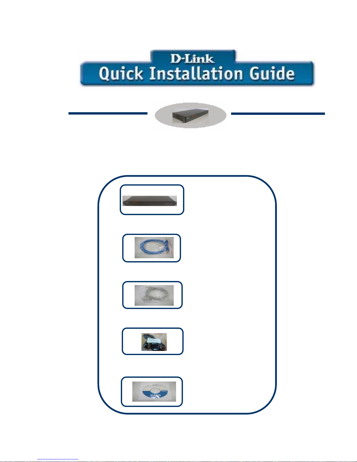
Make sure that the package contains the following items.
• DVX-3500
• 1 Straight
Ethernet cable
• 1 RJ-45 to DB-9
Cable
2 Power cords
•
1
1 User Manual CD
•
Page 2

Before You Begin
• Clamps and
screws
The default IP address for the DVX-3500 is 10.0.0.1 with a
Subnet Mask of 255.0.0.0.You will need to assign your
computer a static IP address within the same range as the DVX3500 IP address (10.0.0.x), e.g. 10.0.0.2 to configure it. To
restore DVX-3500 to factory default, Press the reset switch
placed at the front side of the unit.
The product is equipped with Redundant Power Supply (RPS),
which will keep the unit ON in case of failure of either of the
Power Supply modules (PSU1 & PSU2). These Power Supply
units can be replaced without powering the System down.
2
Page 3

Front View
Power
LED
PSU 1
LED
PSU 2
LED
Alarm
LED
Rear View
10/100Tx
LAN Port
CONSOLE
Port
LAN
LAN
LED
Reset
Switch
Dual 220V AC
Power Supply
Buzzer
Switch
3
Page 4
Connecting DVX-3500
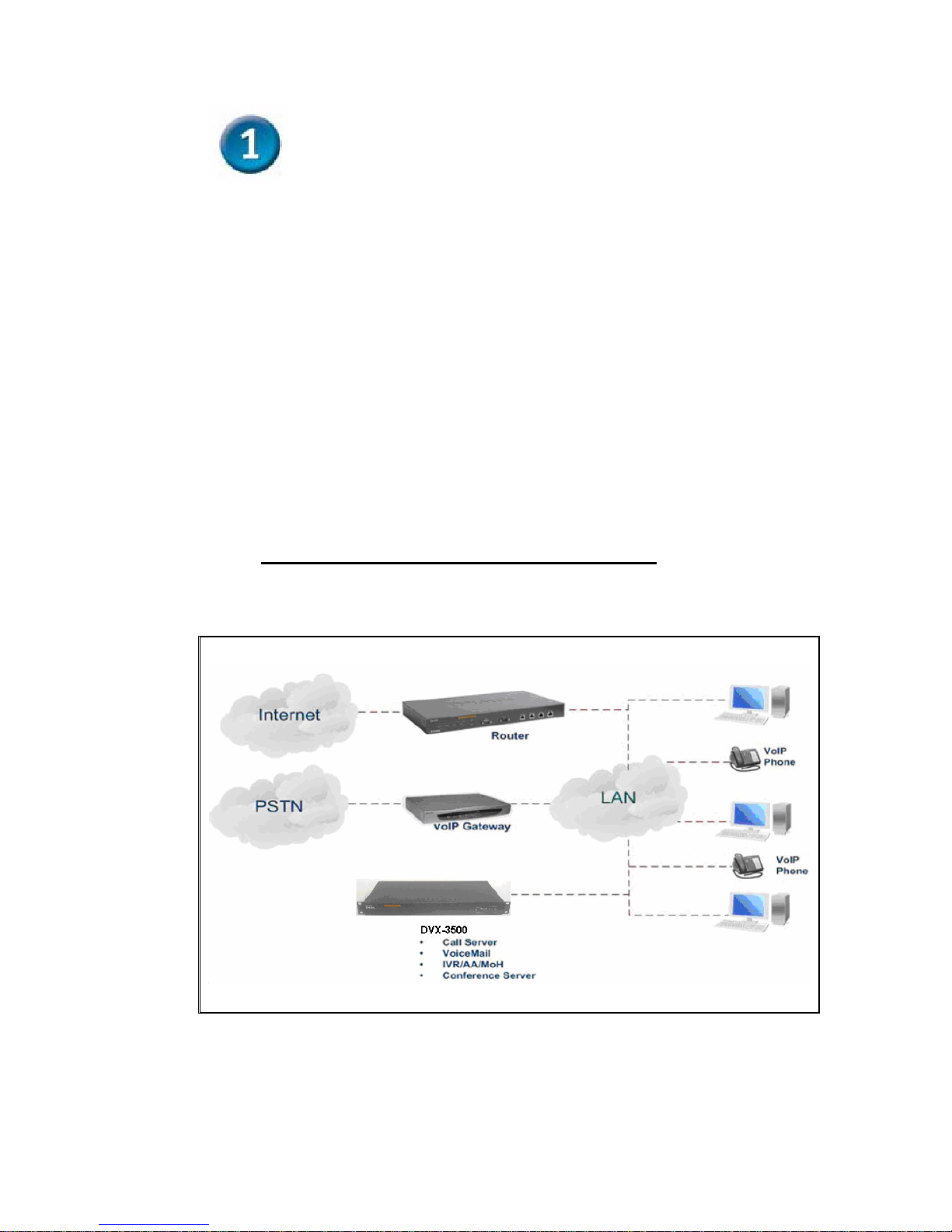
A. Connect two Power cords to the two Power Supply modules
of DVX-3500 and power ON the unit. The Power Led
will turn ON.
B. Connect the LAN interface to the hub or switch connected
to your internal network using ethernet cable.
C. The LAN indicator Led should glow, if the LAN port is
connected to the local network.
D. Connect the RJ-45 to DB-9 Console Cable from the unit to
the Com Port of the PC
DVX-3500 IPPBX Connection Diagram
4
Page 5
Configuring DVX-3500
A computer connected on your LAN network must be assigned
an IP address and subnet mask from the same range as the IP
address and Subnet mask assigned to DVX-3500. The IPPBX
by default is assigned an IP address of 10.0.0.1 with a subnet
mask of 255.0.0.0. It can be configured in 2 ways, Web page
and Command Line Interface (CLI).
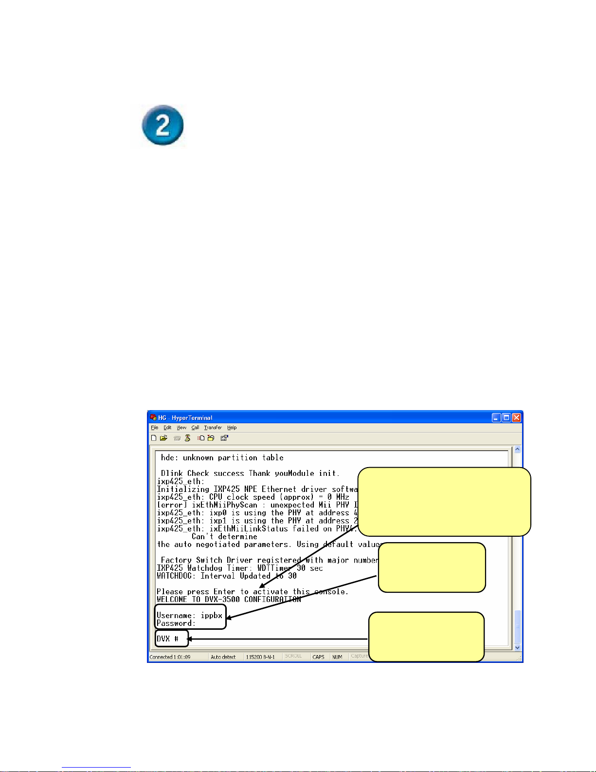
1.
Connect a console cable from the console Port of IPPBX
to ‘Com’ port of your PC and open the hyper terminal.
The terminal settings should be 115200 8-N-1-N.
After the board boots up fully, the
message ‘Please press enter to
activate this console’ will be
displayed on the console.
Press Enter to login
Username: ‘ippbx’
Password: ‘ippbx’
5
‘DVX#’ prompt will
appear
Page 6
2.
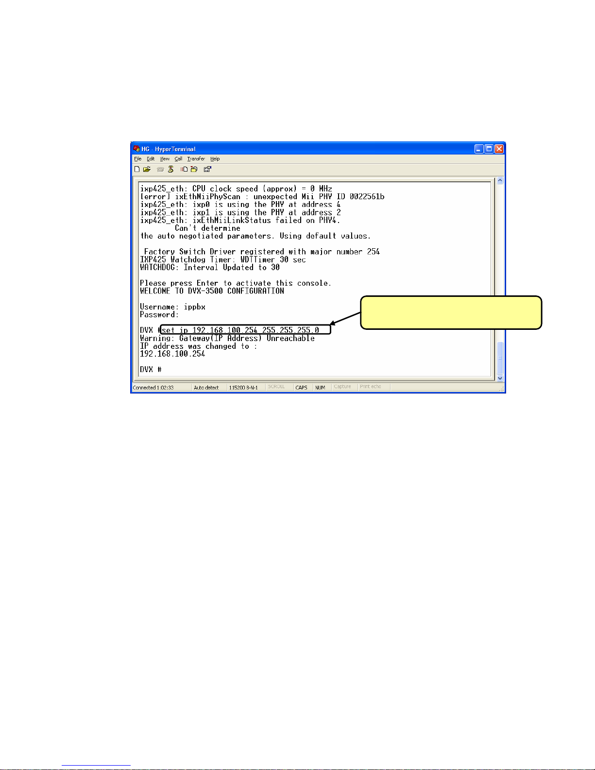
To change the IP use the following command
Set ip < IP address> <netmask>
Use the following command to change
the ip address
6
Page 7
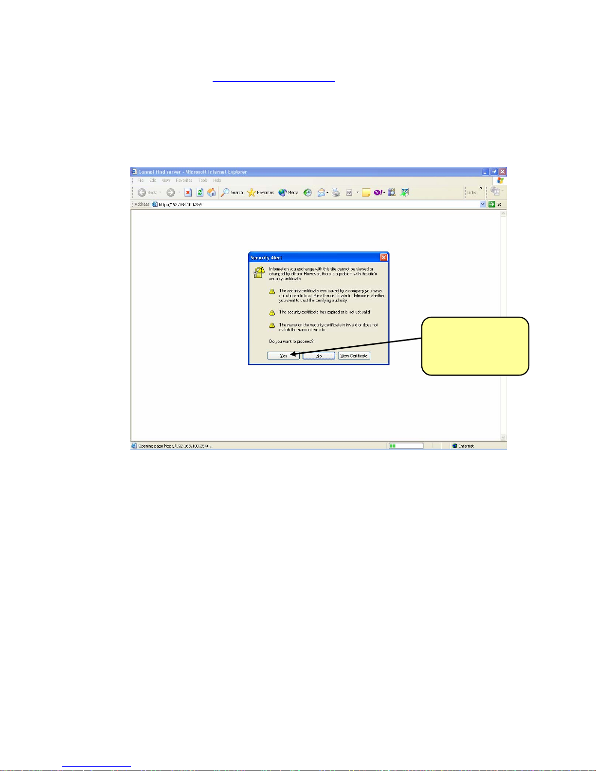
3. Connect to http://<IP address> using
Internet Explorer.
Check whether the PC is in the same IP range and the Proxy
is disabled.
The Security Alert
window will appear.
Click on ‘yes’
7
Page 8
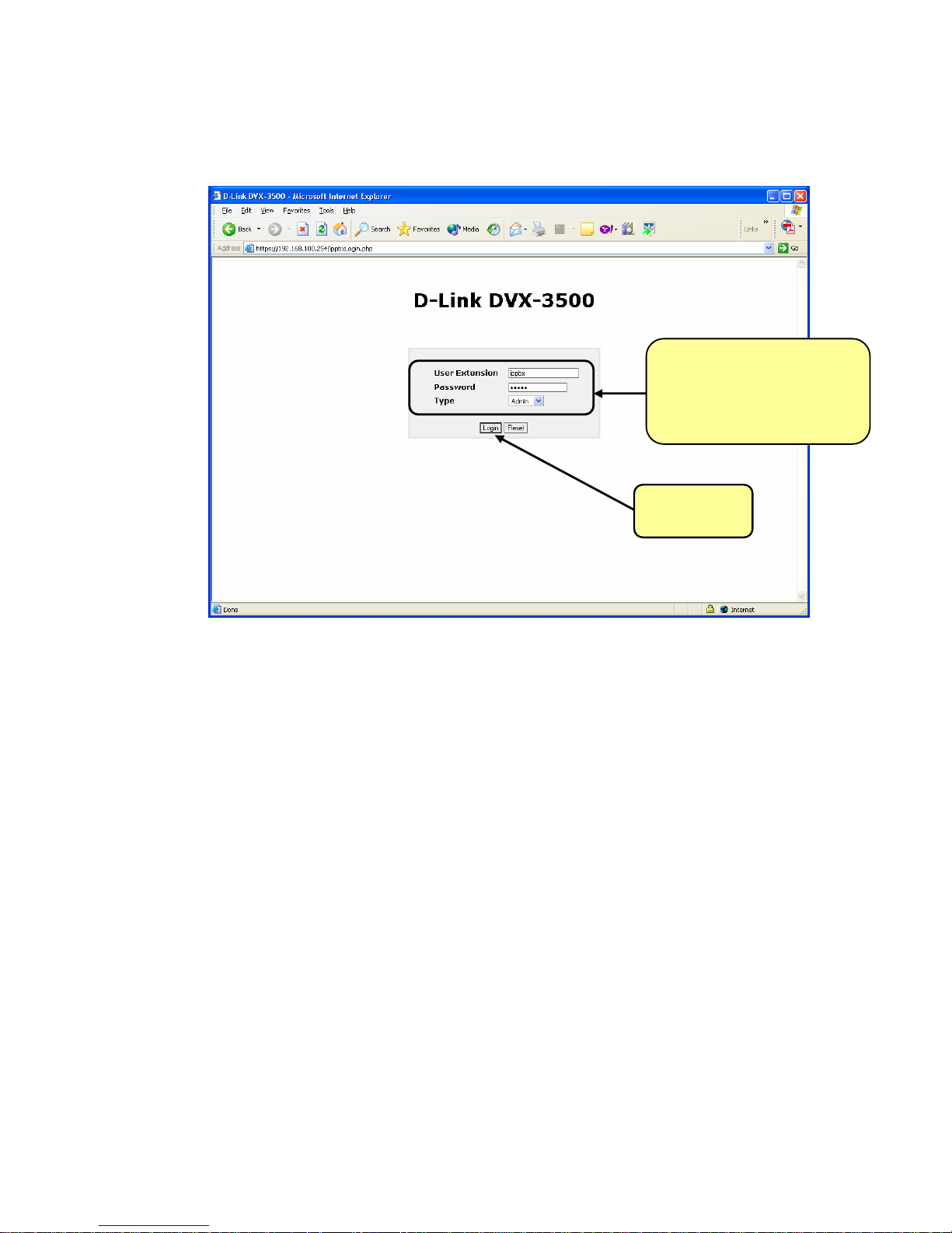
4. Login page will appear
yp
User Extension: ‘ippbx’
Password: ‘ippbx’
e: Admin
T
Click on login
8
Page 9
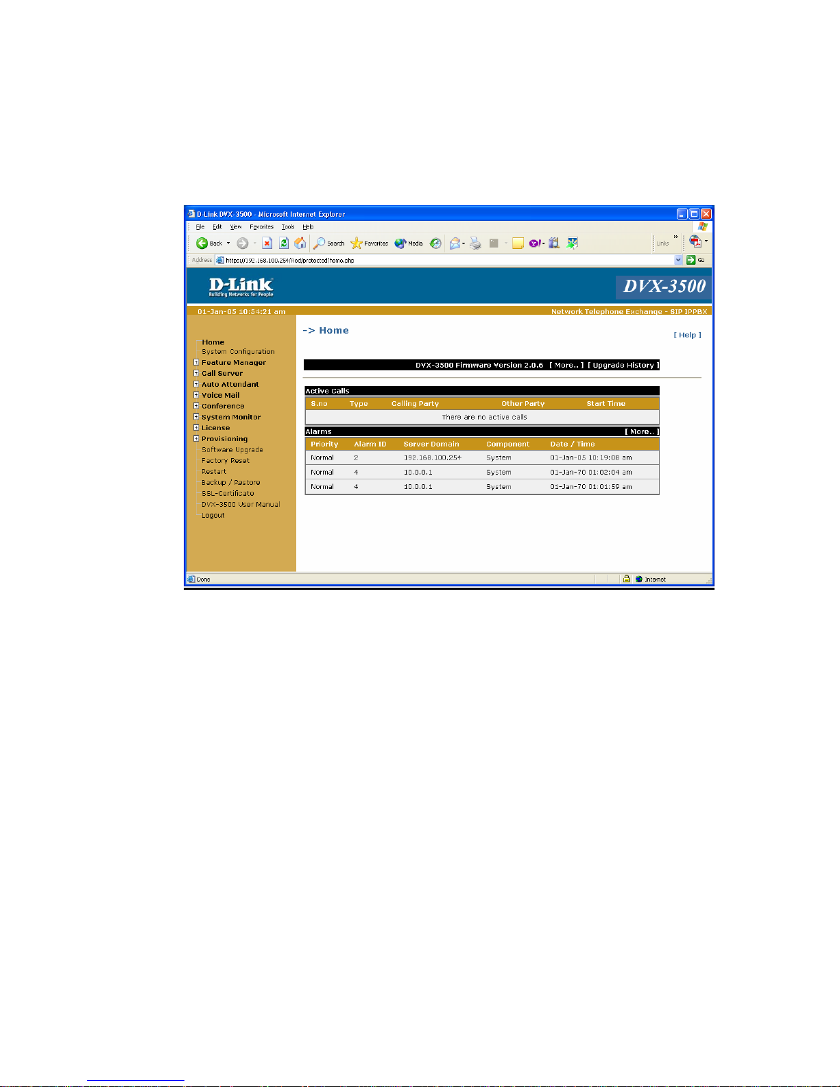
5. D-Link welcome page will appear and you can browse
through it.
9
Page 10
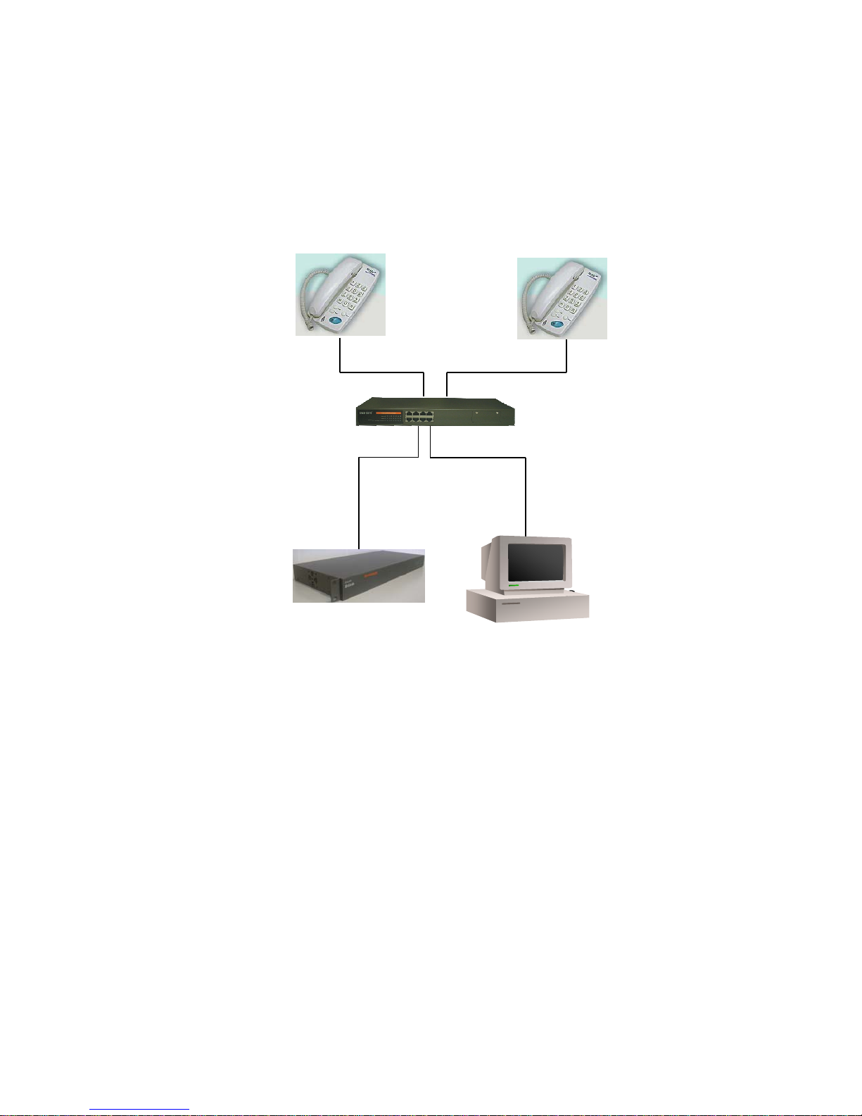
CONFIGURATION SETTINGS TO ADD USERS IN DVX-3500
IP : 192.168.100.20
SIP Proxy Server :192.168.100.254
IP: 192.168.100.21
SIP Proxy Server:192.168.100.254
IP PHONE
111
IP PHONE
222
IP: 192.168.100.254
Hub or Switch
-
The above figure explains the setup on how to add users in
DVX-3500. Use preconfigured IP phones which are in the same
subnet as that of DVX-3500. The gateway of the IP phones
should be that of the IPPBX. Settings which are to be made on
the Device Manager web page are shown below.
10
Page 11
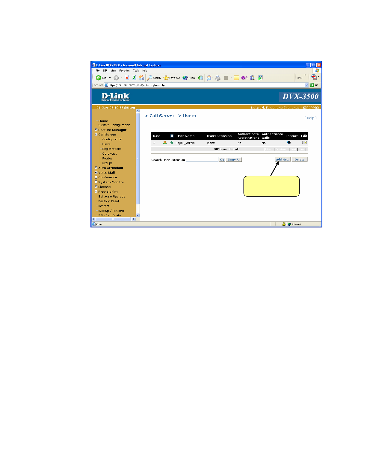
1. Open the DVX-3500 web page and go to Call server> users
Click on ‘Add
a new user’
11
Page 12
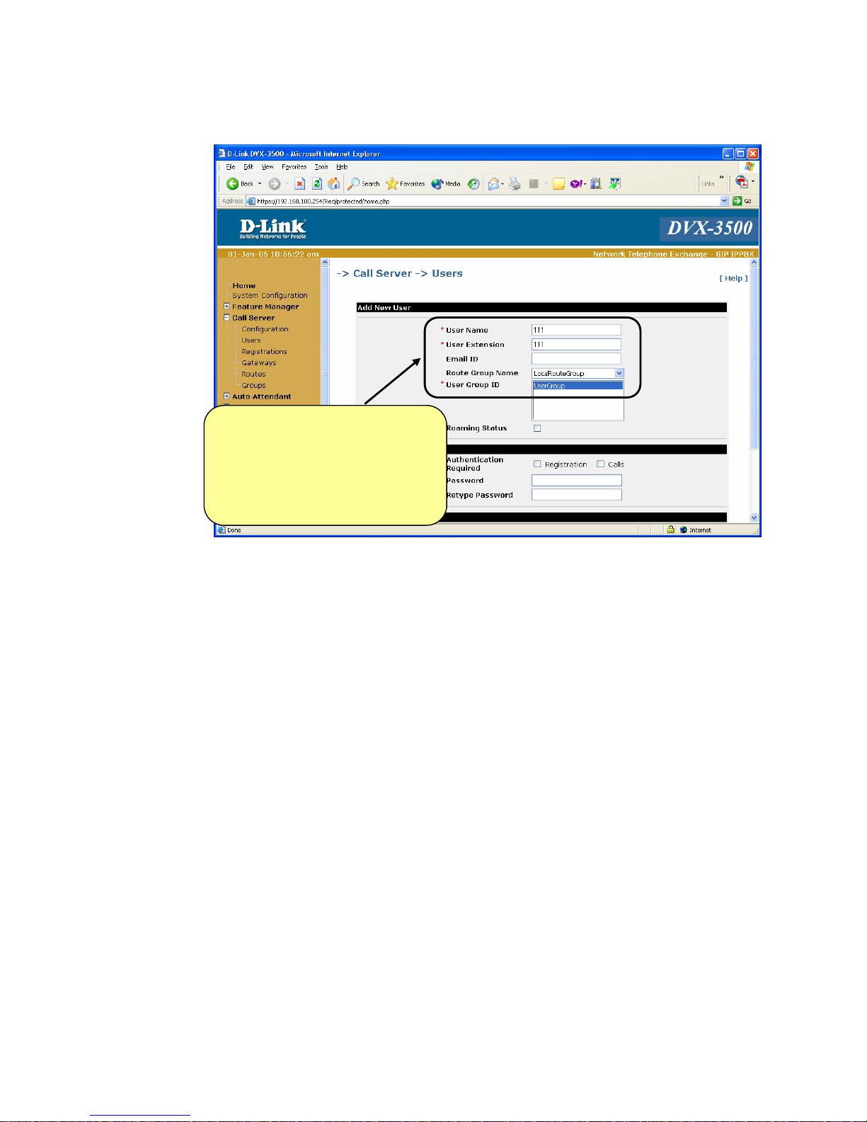
2. User details to be configured as below
User Name : 111
User Extension:111
Select User Group and click,
“Apply”
12
Page 13
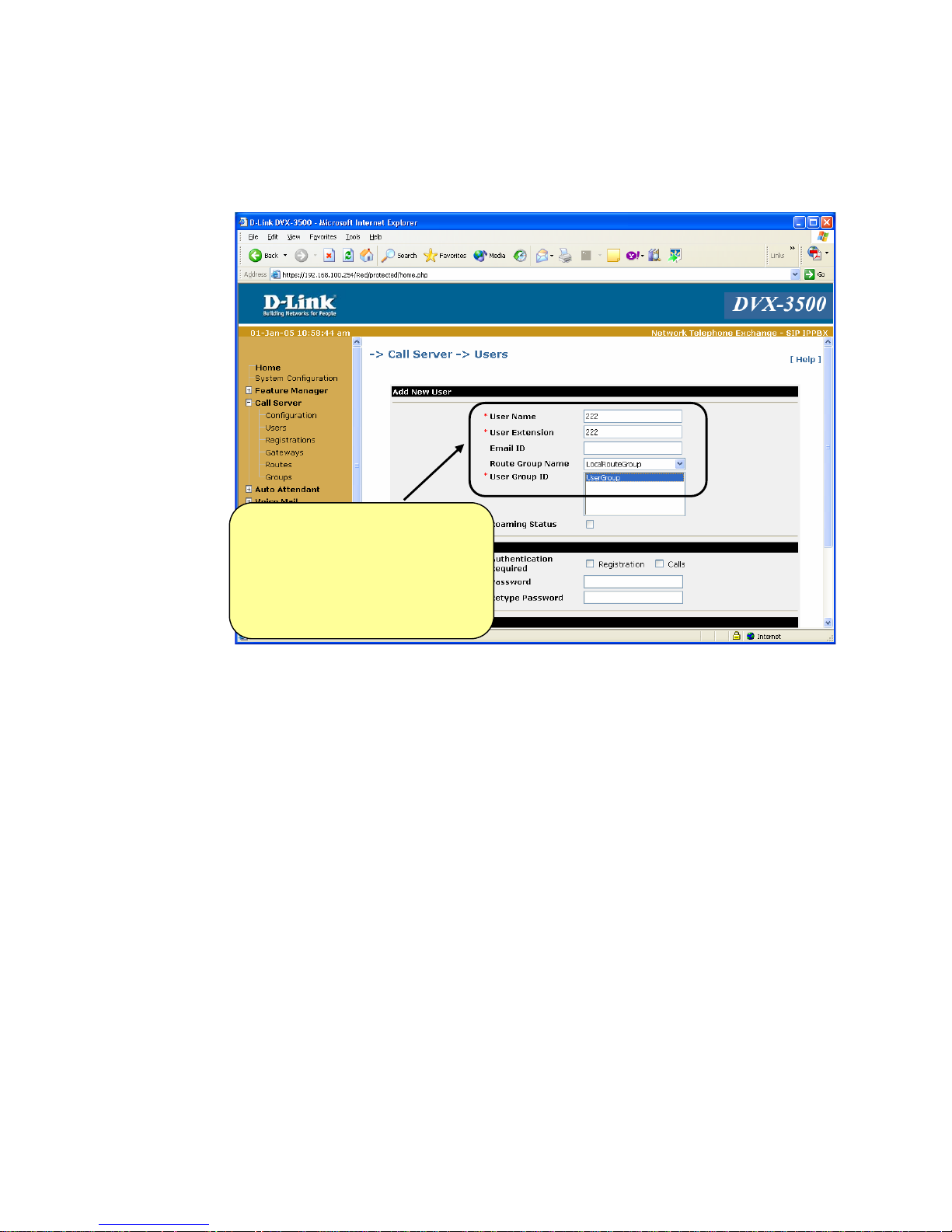
Similarly add the second user, i.e. 222 following the same
above procedure.
User Name : 222
User Extension:222
Select User Group and click,
“Apply”
13
Page 14

3 To view the users go to Call Server> Users. Here you
can view the Users.
Here you can view the
users configured
14
Page 15
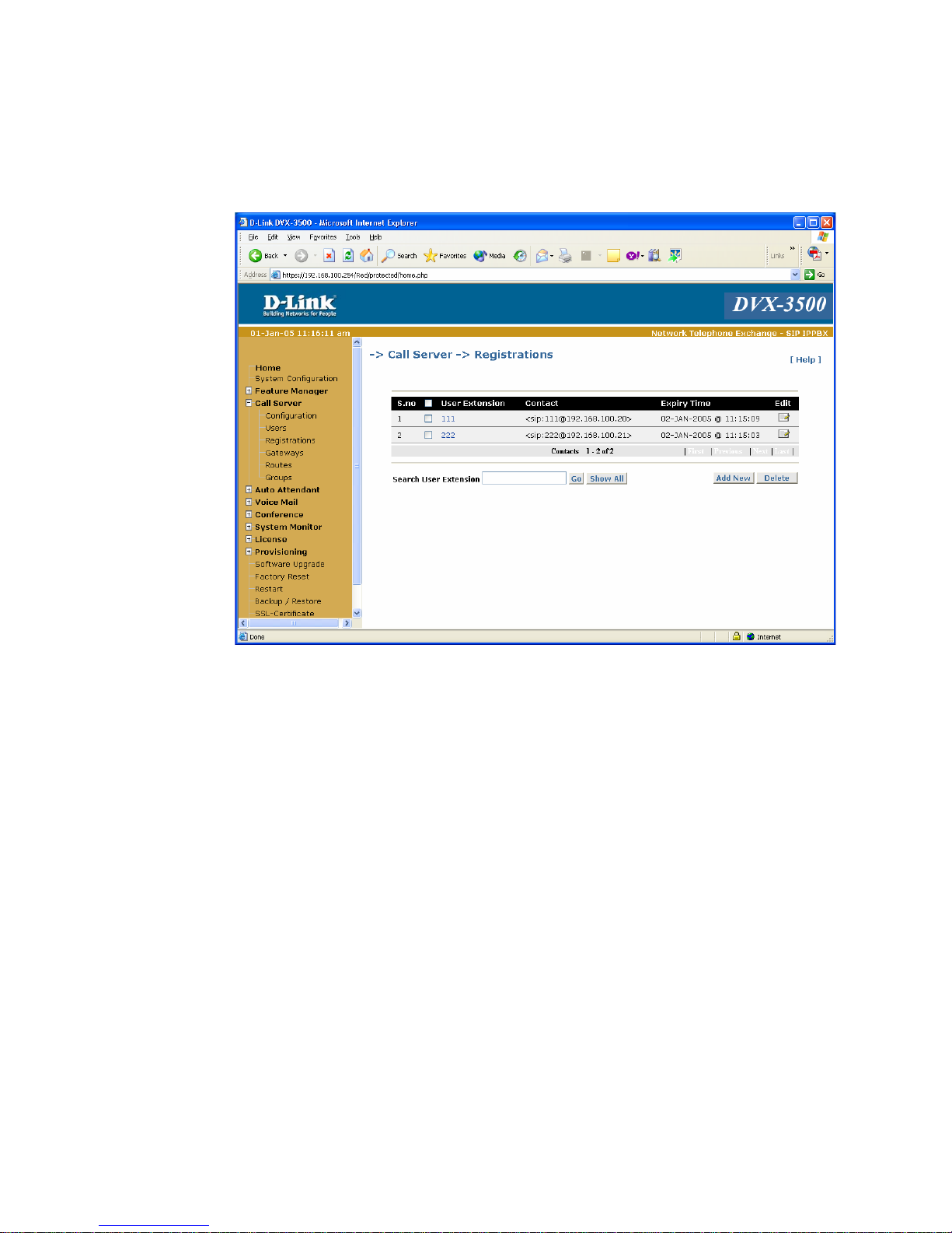
4 To view registrations, first save settings and restart the IP
phones. Then on web configuration of DVX-3500 go to
Call Server> Registrations.
15
Page 16
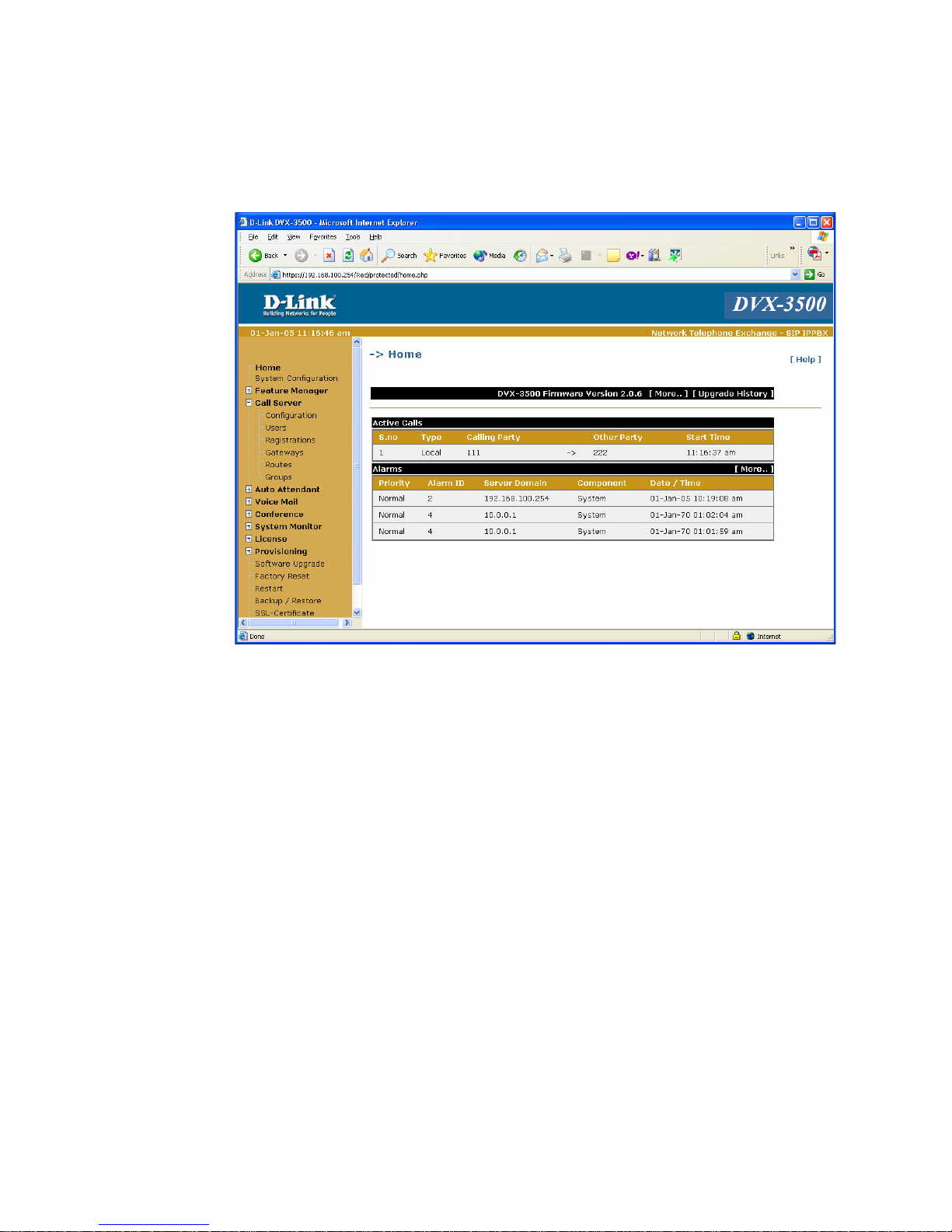
5 Now make a call from one phone to the other i.e. from
111 to 222. The status of the active call can be seen on the
Device manager home page.
16
Page 17
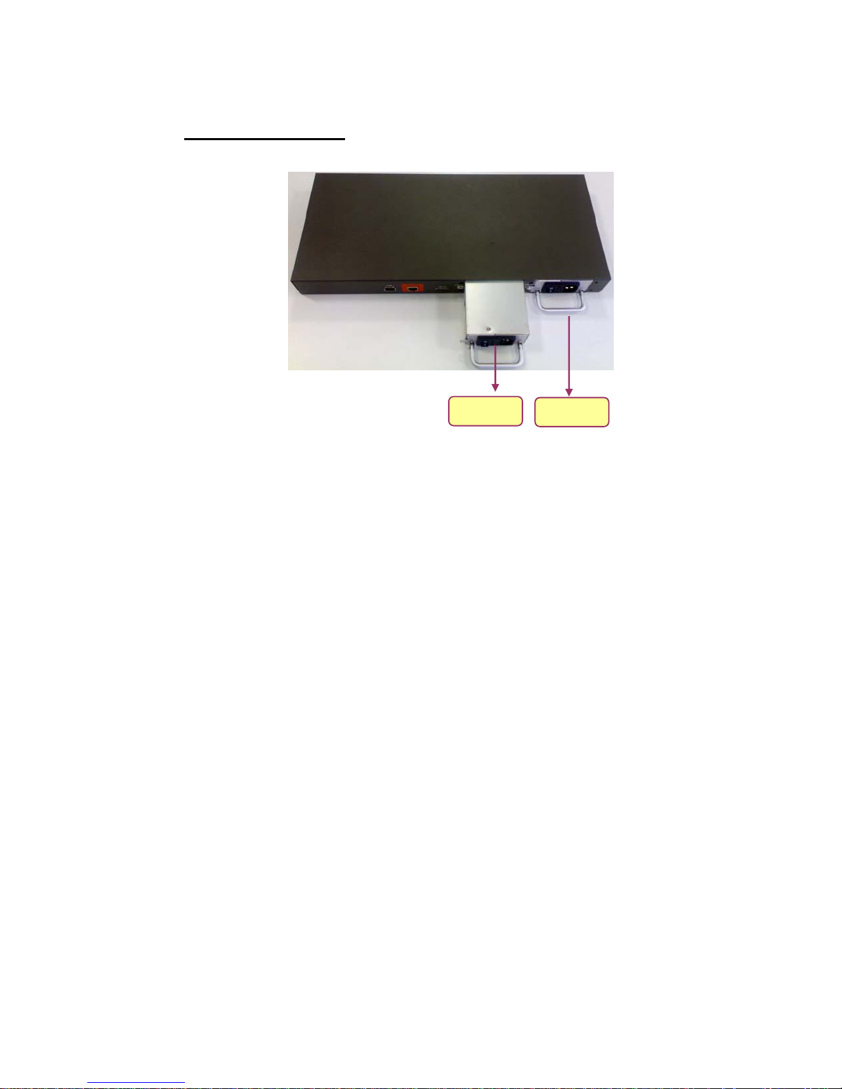
Note: -
RPS Functioning
PSU 1
IPPBX can be Powered UP using either one or both the Power
Supply modules. The Load will be taken by PSU1 or PSU2
whichever is switched ON first.
PSU 2
If one PSU fails then the other PSU will Power the Product without
affecting the normal working of the Product. The buzzer starts
buzzing and the failure LED glows. To stop the buzzer we have to
press Buzzer Reset Switch.
As shown above, the failed PSU can be removed and replaced
without Switching OFF the Product.
17
Page 18
Appendix
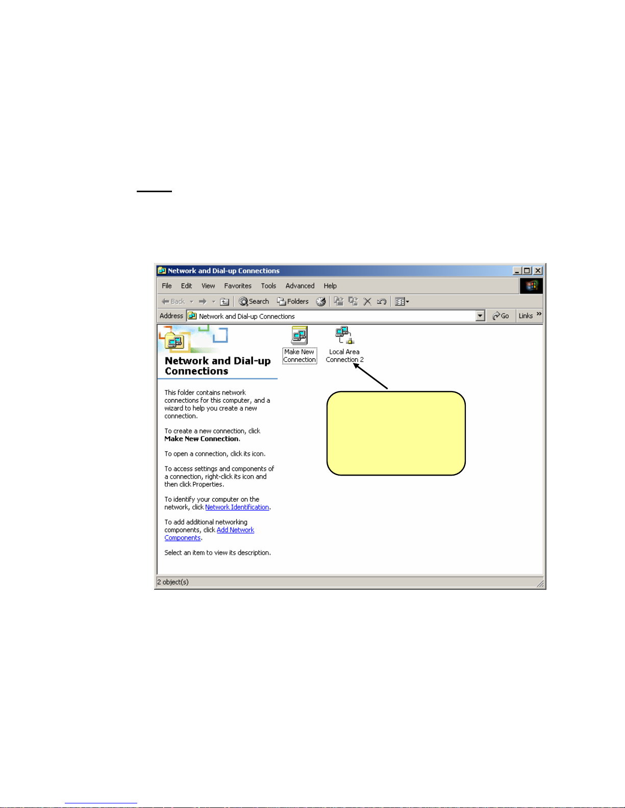
Assigning a Static IP address for your network adapter
The examples below are using a Microsoft Windows 2000 OS.
Note:
Screens in other Operating Systems will look a bit
different, but the steps are the same.
1. Right Click ‘My Network Places’
Right Click ‘local
Area Connection’
icon & select the
properties option
from the pull-down
18
Page 19
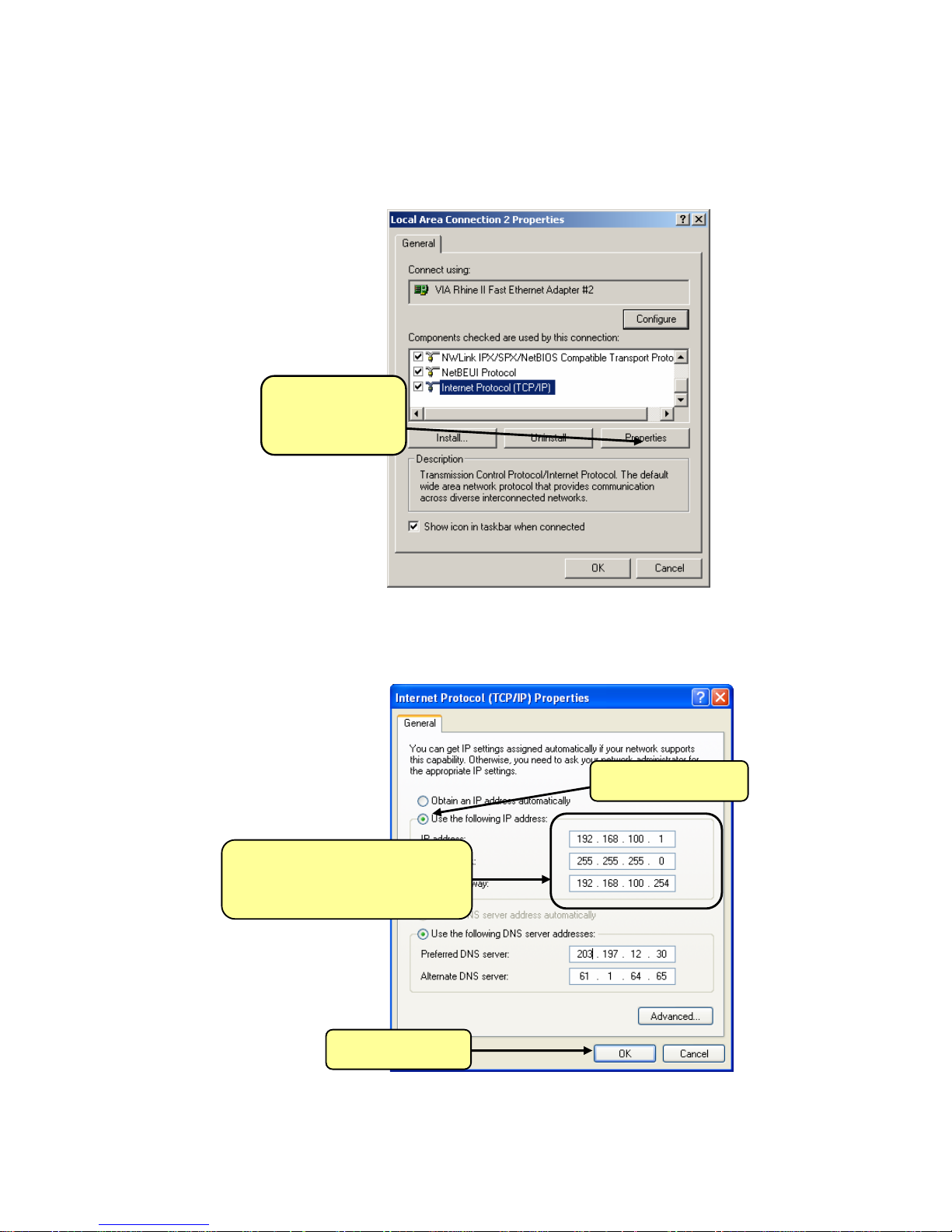
2. In the general tab of the Local Area Connection
Properties menu, highlight Internet protocol (TCP/IP).
Click on
Properties
3. Configure the below page as follows
Assign the following:
IP address: 192.168.100.1
Subnet mask: 255.255.255.0
Default Gateway: 192.168.100.254
Select Use the
following IP address
19
Click OK
 Loading...