

Page 1
DFE-2600 Series
Ethernet/Fast Ethernet
Dual-Speed
Managed/Unmanaged
Stackable Hubs
User Guide
Rev. 03 (December, 1998)
6DFE2600M.03
Printed In Taiwan
RECYCLABLE
Page 2

ii
Trademarks
Copyright 1998 D-Link Corporation.
Contents subject to change without prior notice.
D-Link is a registered trademark of D-Link Corporation/D-Link Systems, Inc.
All other trademarks belong to their respective proprietors.
Copyright Statement
No part of this publication may be reproduced in any form or by any means or
used to make any derivative such as translation, transformation, or adaptation
without permission from D-Link Corporation/D-Link Systems Inc., as stipulated by the United States Copyright Act of 1976.
Page 3

iii
Wichtige Sicherheitshinweise
1. Bitte lesen Sie sich diese Hinweise sorgftig durch.
2. Heben Sie diese Anleitung f den spern Gebrauch auf.
3. Vor jedem Reinigen ist da s Ger vom Stromnetz zu trennen. Vervenden Sie keine Fl sig- oder
Aeros o lreiniger. Am besten d ient ein angefeuchtetes Tuch z ur Reinigung.
4. Um eine Beschigung des G eres zu vermeiden sollten Sie nur Zubehteile ve rwende n, die vom
Hersteller zuge lassen sind.
5. Das Ger is vor Fe uchtigkeit zu sch zen.
6. Bei der Aufstellung des Geres ist auf sichern Stand zu achten. Ein Kippen oder Fallen knte
Verletzungen hervorrufen. V erwenden Sie nur sichere St andorte und beachten Sie die Aufstellhinweise des
Herstellers.
7. Die Bel tungsfnungen dienen zur Luftzirkulation die d as Ger vor erhitzung sch zt. Sorgen Sie
daf , daß diese fnungen nicht abgedec kt werd en.
8. Beachten Sie beim Anschluß an das Stromnetz die Anschluerte.
9. Die Netzanschluteckdose muß aus Gr den der elektrischen Sicherheit einen Schutzleiterkontakt haben.
10. Verlegen Sie die Netzanschlueitung so , daß niemand dar er fallen kann. Es sollete auch nichts auf der
Leitung abgestellt werde n.
11. Alle Hinweise und Warnungen die s ich am Geren befinden sind zu beachten.
12. Wird das Ger er einen lgeren Zeitraum nicht benutzt, sollten Sie es vom Stromnetz trennen. Somit
wird im Falle einer erspannung eine Bes chigung vermiede n.
13. Durch die L tungsfnungen d fen niemals Gegenstde oder Fl sigkeiten in das Ger gelangen.
Dies knte einen Brand bzw. Elektrischen Schlag auslen.
14.
fnen Sie niemals das Ger. Das Ger darf aus Gr den der elektrischen Sicherheit nur von
authorisiertem Servicepersonal gefnet werden.
15. Wenn folge nde Situationen auftreten is t das G er vom Stromnet z zu tre nnen und von eine r qualifizierten
Servicestelle zu erpr en:
a– Netzkabel oder Netzstecker sint beschigt.
b– Fl sigkeit ist in das Ger eingedrungen.
c– Das Ger war Feuchtigkeit ausgesetzt.
d– Wenn da s Ger nicht der Bedienungs anleitung ens prechend funktioniert oder S ie mit Hilfe dieser
Anleitung ke ine Verbesse r ung erziele n.
e– Das Ger ist gefa llen und/oder das Gehse ist beschigt.
f– Wenn da s Ger deutliche Anzeichen eines Defektes aufweist.
16. Bei Reparatur en d fen nur Orginalersatzteile bzw. den Orginalteilen entsprechende Teile ver wendet
werden. Der E insatz von ungeeignete n E r satzt eilen kann e ine weite r e Beschigung hervorrufen.
17. Wenden Sie sich mit allen Fragen die Service und Repartur betreffen an Ihren Servicepartner. Somit
stellen Sie die Betriebssicherheit des Geres sicher.
Page 4

iv
Limited Warranty
Hardware:
D-Link wa r rants its hardware pro ducts to be free from defects in workmanship and mat erials, under normal use
and service, for the following periods measured from date of purchase from D-Link or its Authorized Reseller:
Product Type Warranty Period
Complete products One year
Spare parts and spare kits 90 days
The one-year period of warranty on complete products applies on condition that the product's Registration Card
is filled out and returned to a D- Link office within ninety (90) days of purcha se. A lis t of D-Link o ffices is
provided at the back of this manual, together with a copy of the Registration Card. Failing such timely registration of purchase, the warranty period shall be limited to 90 days.
If the pr oduct proves d efective within the a pplicab le warranty period, D-Link will provide repa ir or replacement
of the product. D-Link shall have the sole discretion whether to repair or replace, and replacement product may
be new or reconditioned. Replacement product shall be of equivalent or better specifications, relative to the
defective product, but need not be identical. Any product or part repaired by D-Link pursuant to this warranty
shall have a warranty period of not less than 90 days, from date of such repair, irrespective of any earlier expiration of original warranty period. When D-Link provides replacement, then the defective product becomes the
property of D-Link.
Warranty service may be obtained by contacting a D-Link office within the applicable warranty period, and
requesting a Return Material Authorization (RMA) number. If a Registration Card for the product in question
has not been returned to D-Link, then a proof of purchase (such as a copy of the dated purchase invoice) must
be provided. If Purchaser's circumstances require special handling of warranty correction, then at the time of
requesting RMA number, Purchaser may also propose special procedure as may be suitable to the case.
After an RMA number is issued, the defective product must be packaged securely in the original or other
suitab le shipping packa ge to ensure that it will not b e damaged in transit, and t he RMA number must be p r ominently marked on the outside of the package. The package must be mailed or otherwise shipped to D-Link with
all costs of mailing/shipping/insurance prepa id ; D-Link will o rdinarily re imburse Purchaser for mailing/shipping/insurance expenses incurred for return of defective product in accordance with this warranty.
D-Link shall never be responsible for any software, firmware, information, or memory data of Purchaser contained in, stored on, or integrated with any product returned to D-Link pursuant to this warranty.
Any pack age retur ned to D- Link without an RMA number will be reje cted a nd shippe d back to Purchaser at
Purchaser's expense, and D-Link reserves the right in such a case to levy a reasonable handling charge in addition mailing or shipping costs.
Software:
Warranty service for software products may be obtained by contacting a D-Link office within the applicable
warranty period. A list of D-Link offices is provided at the back of this manual, together with a copy of the
Registration Card. If a Registration Card for the product in question has not been returned to a D-Link office,
then a proof of purchase (such as a copy of the dated purchase invoice) must be provided when requesting
warranty service. The term "purchase" in this software warranty refers to the purchase transaction and resulting
license to use such software.
D-Link warrants that it s software p roducts will perform in subs tantial conformance with the applic able pr oduct
documentation provided by D-Link with such software product, for a period of ninety (90) days from the date of
purcha se from D-Link or its Authorized Reseller. D-Link warrants the magnetic media , on which D-Link
provides its software product, against failure during the same warranty period. This warranty applies to pur-
Page 5

v
chased software, and to replacement software provided by D-Link pursuant to this warranty, but shall not apply
to any update or replacement which may be provided for download via the Internet, or to any update which may
otherwise be provided free of charge.
D-Link's sole obligation under this software warranty shall be to replace any defective software product with
product which substantially conforms to D-Link's applicable product documentation. Purchaser assumes responsibility for the selection o f appropriate application and syste m/platform s oftware and associated r eference
materia ls. D-Link makes no warrant y that its softwa re prod ucts will work in combination with any hardware, or
any application or system/platform software product provided by any third party, excepting only such products
as are expressly represented, in D-Link's applicable product documentation as being compatible. D-Link's
obligation under this warranty shall be a re asonab le effort to provide compa tibility, but D-Link shall have no
obligat ion to provide co mpatibility w hen there is fault in t he third-party hardware or software. D-Link makes no
warranty that operation of its softwa re prod u cts will b e uninterrup ted or absolut ely error - fr ee, a nd no warr anty
that all defects in the software product, within or without the scope of D-Link's applicable product documentation, will be co rrected.
D-Link Offices for Registration and Warranty Service
The product's Registration Card, included at the back of this manual, must be completed and sent to a D-Link
office. To obtain an RMA number for warranty service on a hardware product, or software product, contact the
D-Link office nearest you. An address / telephone / fax contact list of international D-Link offices is provided at
the back of this manual.
LIMITATION OF WARRANTIES
IF THE D-LINK PRODUCT DOES NOT OPERATE AS WARRANTED ABOVE, THE CUSTOMER'S
SOLE REMEDY SHALL BE, AT D-LINK'S OPTION, REPAIR OR REPLACEMENT. THE FOREGOING
WARRANTIES AND REMEDIES ARE EXCLUSIVE AND ARE IN LIEU OF ALL OTHER
WARRANTIES, EXPRESSED OR IMPLIED, EITHER IN FACT OR BY OPERATION OF LAW,
STATUTORY OR OTHERWISE, INCLUDING WARRANTIES OF MERCHANTABILITY AND FITNESS
FOR A PARTICULAR PURPOSE. D-LINK NEITHER ASSUMES NOR AUTHORIZES ANY OTHER
PERSON TO ASSUME FOR IT ANY OTHER LIABILITY IN CONNECTION WITH THE SALE,
INSTALLATION MAINTENANCE OR USE OF D-LINK'S PRODUCTS
D-LINK SHALL NOT BE LIABLE UNDER THIS WARRANTY IF ITS TESTING AND EXAMINATION
DISCLOSE THAT THE ALLEGED DEFECT IN THE PRODUCT DOES NOT EXIST OR WAS CAUSED
BY THE CUSTOMER'S OR ANY THIRD PERSON'S MISUSE, NEGLECT, IMPROPER INSTALLATION
OR TESTING, UNAUTHORIZED ATTEMPTS TO REPAIR, OR ANY OTHER CAUSE BEYOND THE
RANGE OF THE INTENDED USE, OR BY ACCIDENT, FIRE, LIGHTNING OR OTHER HAZARD.
Page 6

vi
LIMITATION OF LIABILITY
IN NO EVENT WILL D-LINK BE LIABLE FOR ANY DAMAGES, INCLUDING LOSS OF DATA, LOSS
OF PROFITS, COST OF COVER OR OTHER INCIDENTAL, CONSEQUENTIAL OR INDIRECT
DAMAGES ARISING OUT THE INSTALLATION, MAINTENANCE, USE, PERFORMANCE, FAILURE
OR INTERRUPTION OF A D- LINK PRODUCT, HOWEVER CAUSED AND ON ANY THEORY OF
LIABILITY. THIS LIMITATION WILL APPLY EVEN IF D-LINK HAS BEEN ADVISED OF THE
POSSIBILITY OF SUCH DAMAGE.
IF YOU PURCHASED A D-LINK PRODUCT IN THE UNITED STATES, SOME STATES DO NOT
ALLOW THE LIMITATION OR EXCLUSION OF LIABILITY FOR INCIDENTAL OR CONSEQUENTIAL
DAMAGES, SO THE ABOVE LIMITATION MAY NOT APPLY TO YOU.
FCC Warning
This equipment has been tested and found to comply with the limits for a
Class A digital device, pursuant to Part 15 of the FCC Rules. These limits are
designed to provide reasonable protection against harmful interference when
the equipment is operated in a commercial environment. This equipment
generates, uses, and can radiate radio frequency energy and, if not installed
and used in accordance with this user guide, may cause harmful interference to radio communications. Operation of this equipment in a residential
area is likely to cause harmful interference in which case the user will be required to correct the interference at his own expense.
CE Mark Warning
This is a Class A product. In a domestic environment, this product may cause
radio interference in which case the user may be required to take adequate
measures.
VCCI A Warning
Page 7

About This Guide vii
T
ABLE OF
C
ONTENTS
0 A
BOUT THIS GUIDE
.........................................................
XI
Models Covered........................................................................................xi
Conventions..............................................................................................xi
Overview of the User Guide ................................................................xii
1 I
NTRODUCTION
.................................................................1
Product Description..................................................................................1
Product Features.......................................................................................2
Dual-Speed Ethernet Hub Technology Overview......................................4
2 U
NPACKING AND SETUP
....................................................6
Unpacking .................................................................................................6
Identifying External Components..............................................................7
Front Panel..........................................................................................................7
Rear Panel...........................................................................................................9
Installing the Hub....................................................................................10
Installation ........................................................................................................10
Rack Mounting..................................................................................................11
Replacing the Power Supply....................................................................12
3 U
NDERSTANDING INDICATORS
.........................................15
Hub State Indicators................................................................................16
Page 8

Dual-Speed Stackable Hubs User’s Guide
viii
Module Indicators...................................................................................17
Port State Indicators ...............................................................................18
SNMP Indicator.......................................................................................19
Port Speed Indicators..............................................................................19
Console Port Indicator (CON) ................................................................19
4 M
AKING CONNECTIONS
...................................................21
Hub Cascading/Building a Stack.............................................................21
Connectivity Rules...................................................................................23
The Diagnostic Port ................................................................................24
Diagnostic Port Connection..............................................................................24
Hub to End-Station Connection ..............................................................25
Hub-to-Hub Uplink..................................................................................27
Optional Module Connections.................................................................29
Module Installation...........................................................................................30
Switch Module (DFE-260S).............................................................................31
Fiber Optic Module (DFE-260FX)...................................................................31
Fast Ethernet Module (DFE-260TX)................................................................32
5 M
ASTER HUB SETUP AND MANAGEMENT
..........................35
Navigation and Conventions...................................................................36
In-Band Setup Instructions......................................................................37
Backup Master Function.........................................................................38
Segmenting Hubs.....................................................................................39
Logging in to the Hub Console................................................................41
Logging In.........................................................................................................41
Changing Your Password..................................................................................43
Setting Up the Master Hub......................................................................45
TCP/IP Settings.................................................................................................45
Page 9

ix
Out-of-Band Management and Console Settings..............................................47
Software Update on Boot..................................................................................48
SNMP Information............................................................................................49
SNMP Traps .....................................................................................................51
SNMP Security (Community Names)...............................................................52
Adding and Deleting Users...............................................................................53
Primary/Backup Master.....................................................................................55
Hub Stack Management...........................................................................56
Controlling Hubs in the Hub Stack...................................................................56
Controlling Individual Ports .............................................................................59
Monitoring the Hub Stack .......................................................................60
Displaying Port and Group Statistics................................................................61
Displaying Segment Statistics...........................................................................64
Node Tracking...................................................................................................66
Per-Port Intrusion Security ...............................................................................67
Bridge Information............................................................................................67
Resetting the Hub ....................................................................................68
System Reset.....................................................................................................69
Factory Reset.....................................................................................................69
6 WEB-B
ASED NETWORK MANAGEMENT
............................71
Introduction.............................................................................................71
Getting Started ........................................................................................72
Management............................................................................................72
Configuration....................................................................................................73
Performance......................................................................................................79
Fault..................................................................................................................82
User...................................................................................................................89
RMON ..............................................................................................................92
7 C
ABLES AND CONNECTORS
...........................................111
100BASE-TX Ethernet Cable and Connectors......................................111
Crossover Cables...................................................................................112
RS-232 (DB9) Pin Specification.....................................................................113
Page 10

Dual-Speed Stackable Hubs User’s Guide
x
8 S
PECIFICATIONS
...........................................................119
General..................................................................................................119
Hub-to-Hub Cascading .........................................................................120
LED Indicators......................................................................................120
Environmental and Physical..................................................................120
9 G
LOSSARY
...................................................................123
Page 11

About This Guide xi
0 A
BOUT
T
HIS
G
UIDE
This guide discusses how to install and use the DFE-2600 series dual-speed,
managed/unmanaged, stackable Ethernet/Fast Ethernet Hubs.
Models Covered
Unmanaged Models
: DFE-2616, DFE-2616x, DFE-2624, DFE-2624x.
Managed Models
: DFE-2616i, DFE-2616ix, DFE-2624i, DFE-2624ix.
All ” models include a switch module in Slot 1 of the rear panel. All ”
models are intelligent (that is, anaged”) hubs capable of managing an entire
hub stack. All x” models have both features.
The model numbers also indicate how many ports a partic ular hub has, thus:
2616 hubs have 16 ports and 2624 hubs have 24 ports.
Conventions
References in this manual to the DFE-2616, DFE-2616x, DFE-2624, DFE2624x; DFE-2616i, DFE-2616ix, DFE-2624i, and DFE-2624ix hubs are frequently written simply as ub” or ubs” where the text applies to all
models. Model numbers are normally used only to differentiate between
them where necessary.
At points in this document, master models are differentiated by referring to,
FE-2600 series master hubs.”
Page 12

Dual-Speed Stackable Hubs User’s Guide
About This Guidexii
Unless differentiated by model number or other specific reference, all information applies to all models.
Overview of the User Guide
♦
Chapter 1,
Introduction
. Provides information on Fast Ethernet net-
works, and introduces the features of the DFE-2600 series hubs.
♦
Chapter 2,
Unpacking and Setup
. Helps you get started in setting up
the hub.
♦
Chapter 3,
Understanding Indicators
. Describes all LED indicators
on the hub front panel. Understanding these indicato rs is essential
to effectively using the hub.
♦
Chapter 4,
Making Connections
. Provides information on connecting
to the hub twisted-pair and console po rts, stacking hub s, and linking
with other 100BASE-TX hubs.
♦
Chapter 5,
Master Hub Setup and Management
. Provides information
on using the management agent built into master models in the 2600
series.
♦
Chapter 6,
Web-based Network Management.
Provides detailed in-
formation on managing the network thro ugh an internet browser.
♦
Appendix A,
Cables and Connectors
. Provides specifications on the
cables and connectors used with the hubs.
♦
Appendix B,
Boot Configuration File
. Describes the DFE-2600 series
master hub boot configuration file.
♦
Appendix C,
Specifications
. Lists the hubs’ specifications.
♦
Appendix D,
Glossary
. Provides the meaning for some networking
terms used in this manual.
Page 13
Introduction 1
1
1 I
NTRODUCTION
This chapter introduces the DFE-2600 series dual-speed stackable hubs, as
well as giving some background information about the technology the hubs
use.
Product Description
The D-Link DFE-2600 series dual-speed stackable Ethernet/Fast Ethernet
hubs are designed to allow easy migration and integration between 10Mbps
Ethernet and 100Mbps Fast Ethernet, while providing manageability and
flexibility in cable connections.
The DFE-2600 hubs can operate with either IEEE 802.3 10BASE-T connections (twisted-pair Ethernet operating at 10 megabits per second), or IEEE
802.3u 100BASE-TX connections (twisted-pair Fast Ethernet operating at
100 megabits per second). All of the twisted-pair ports support NWay autonegotiation, allowing the hub to automatically detect the speed o f a network
connection. This means you can connect all of your Ethernet and Fast Ethernet hosts to a DFE-2600 series hub stack, without any rewiring required when
a host is upgraded from 10Mbps to 100Mbps.
The DFE-2600 series hubs, available in 16-port and 24-port models, can be
stacked with up to five hub s in a stack. A sta ck of five 24 -port hubs give s a
total of 120 Ethernet or Fast Ethernet ports. A DFE-2600 series hub stack
operates as a Class II Fast Ethernet repeater, allowing it to be linked to
another Class II Fast Ethernet stack in the same collision domain.
Page 14

Dual-Speed Stackable Hubs User’s Guide
Introduction2
In the basic configuration, the 10Mbps and 100Mbps segments are separate
and do not intercommunicate. An optional DFE-260S switch module (included with the DFE-2616x, DFE-2624x, DFE-2616ix, and DFE-2624ix) can
be installed in any hub in the stack, making it possib le to transp arently br idge
between the 10Mbps and 100Mbps segments. In a managed hub stack, more
than one DFE-260S module can be used to provide redundancy if the two
modules are both in the primary master hub segment..
Other add-in modules are also available, providing 100BASE-TX, or
100BASE-FX connections. DFE-2600 series hubs each have two slots for
accepting slide-in modules.
Product Features
The list below highlights the features and specifications of the DFE-2600
series hubs.
♦
Compatible with the IEEE 802.3 10BASE-T Ethernet and 802.3u
100BASE-TX Fast Ethernet industry standards for interoperability
with other Ethernet/Fast Et hernet network devices.
♦
Ethernet connections support Category 3 or better twisted-pair cables.
♦
Fast Ethernet connections support both shielded twisted pair and
Category 5 unshielded twisted-pair cables.
♦
Fast Ethernet connections support a maximum distance of 100 meters
from end-station to hub, and a total network diameter of 205 meters.
♦
Sixteen (DFE-2616, DFE-2616x, DFE-2616i, DFE-2616ix) or twentyfour (DFE-2624, DFE-2624x, DFE-2624i, DFE-2624ix) NWay RJ-45
ports for connecting stations to the network.
♦
Auto negotiated connection speed (NWay) on each port.
Page 15

Introduction 3
♦
Full hub stack and ne twork management provid ed via a n SNMP management agent (DFE-2616i, DFE-2616ix, DFE-2624i, DFE-2624ix).
♦
An optional slide-in switch module allows bridging between 10Mbps
and 100Mbps segments. Only one switch module is needed per stack,
but managed hub stacks can make use of additional switch modules
for redundancy
.
♦
LED indicators for power, collisions, link, network activity, partitioning status, disable, operating speed (10 or 100Mbps) and network
utilization.
♦
Digital hub ID number front panel display.
♦
Auto-partition protection.
♦
Data collision detection and hand ling.
♦
Preamble re generation, signal retiming.
♦
Two proprietary daisy-chain ports for cascading up to five hubs to
form one logical hub ; manage ment provided via a master hub.
♦
Standby backup master capability when two master model hubs are
present within a single stack.
♦
Uplink port allows easy linking of two Fast Ethernet or fo ur Ethernet
hub stacks to further expand your network.
♦
Standard-size (19”, 1.25U height), rack mountable
♦
Built-in, removable power supply, replaceable without opening the
hub. Power supply is easily removed and replaced. Automatic voltage selection (100V to 240V, 50 or 60Hz) without fuses to change or
a voltage switch to set.
♦
Optional slide-in modules: Switch, 100BASE-TX, and 100BASE-FX
(see Chapter 4
: Making Connections).
Page 16
Dual-Speed Stackable Hubs User’s Guide
Introduction4
Dual-Speed Ethernet Hub
Technology Overview
Dual-speed Ethernet hubs have been developed to make it simpler to plan
networks containing both 10-Mbps Ethernet and 100-Mbps Fast Ethernet
technologies, especially when network hosts are being gradually migrated to
new Fast Ethernet connec tions.
Ethernet and Fast Ethernet workgroups, also called collision domains, are
configured in a star topology where all end-nodes (computers, servers,
bridges, etc.) branch out from a central hub. Two hubs can also be plinked’
to each other to form a much larger collision domain consisting of two linked
stars. And collision d omains can be easily interconnecte d through switching
hubs and bridges to form a network large enough to encompass a high-rise
building or campus enviro nment.
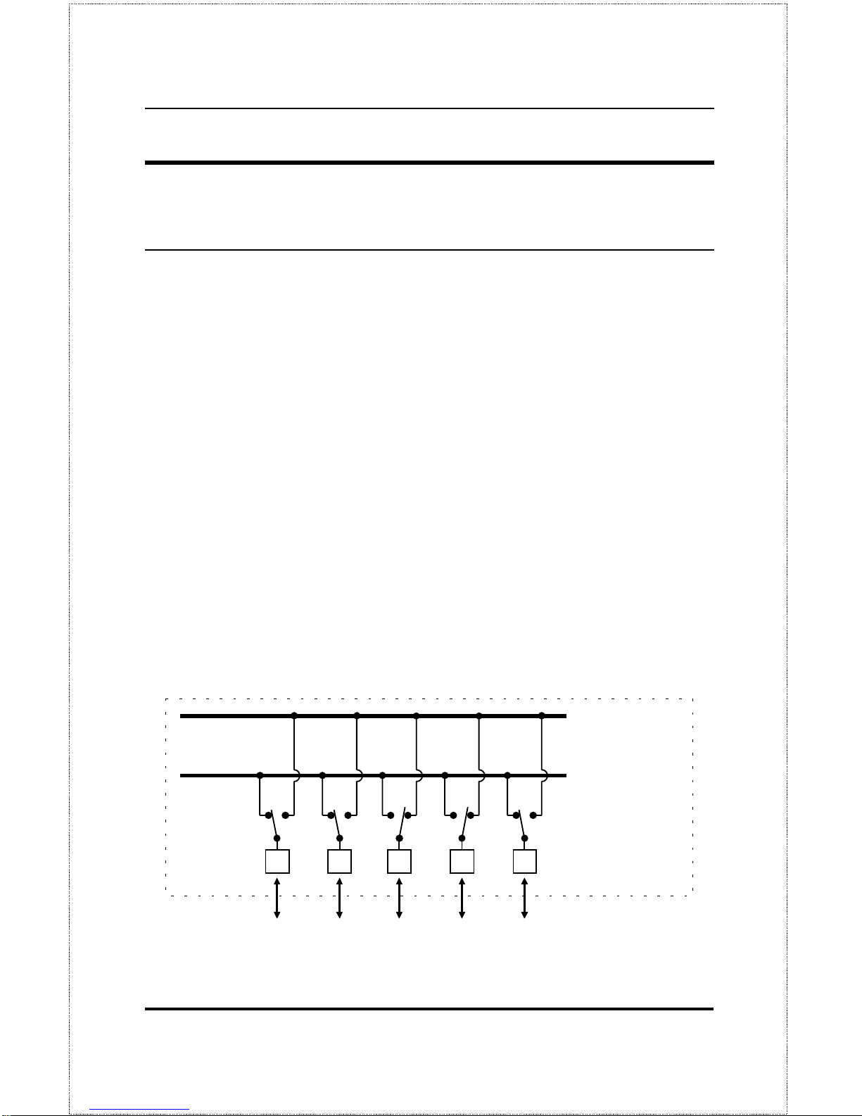
A dual-speed hub is actually two repeaters in one housing. Any device that is
plugged into the hub is automatically connected (by NWay) to the fastest
repeater it can use. The 10-Mbps repeater receives Ethernet transmissions
from any port connected to it, and retransmits them to all other ports operating at 10 Mbps. Similarly, the 100-Mbps repeater retransmits Fast Ethernet
transmissions from ports operating at 100 Mbps to all other ports operating at
the same speed as shown below.
10Mbps Repeater
100Mbps Repeater
NWay Detection
RJ-45 Ports
100Mbps
Ethernet
Station
100Mbps
Ethernet
Station
10Mbps
Ethernet
Station
10Mbps
Ethernet
Station
100Mbps
Ethernet
Station
Page 17
Introduction 5
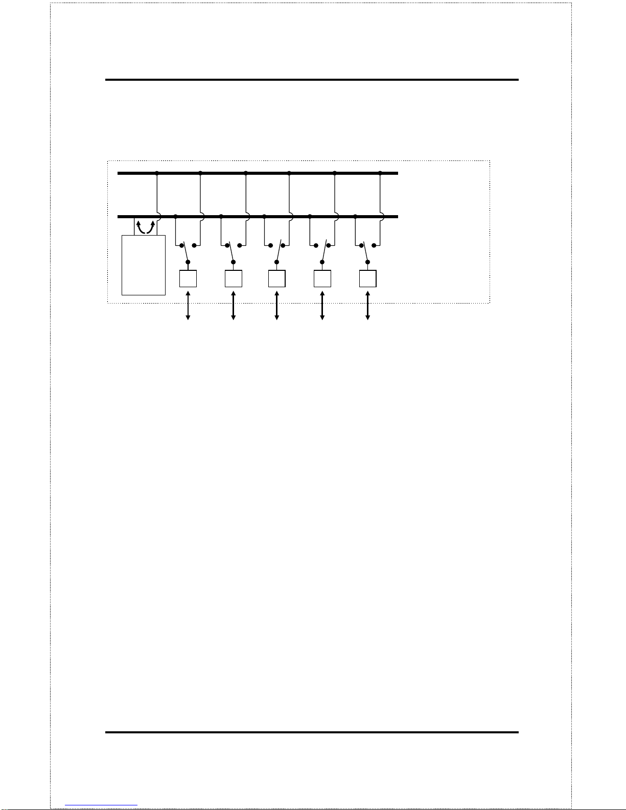
If there is a switching circuit in the hub (or in any hub in a stack), it will serve
as a bridge between the two repeaters.
10Mbps Repeat er
100Mbps Repeat er
NWay Detectio n
RJ-45 Ports
100Mbps
Ethernet
Station
100Mbps
Ethernet
Station
10Mbps
Ethernet
Station
10Mbps
Ethernet
Station
100Mbps
Ethernet
Station
Switching
Circuit
The switching circuit does not, however join the 10Mbp s Ethernet collision
domain with the 100Mbps Fast Ethernet collision domain; it only allows them
to communicate. The two repeaters are two separate collision domains regardless of whether a switching circuit is present.
If a DFE-2600 series hub or hub stack is uplinked through a twisted-pair or
Uplink port to another dual-speed or Fast Ethernet hub or stack, the hub will
function as a Class II Fast Ethernet device and be subject to those connectivity rules. If it is uplinked to a 10BASE-T Ethernet hub or stack (10Mbps
only) then it will function as a normal 10BASE-T Ethernet repeater and is
then subject to those connection rules. And because it is a dual-speed hub
with two separate repeaters, it can connect to both at the same time, counting
as a repeater in each of the collision domains. For more detailed information,
please refer to Chapter 4,
Making Connections
.
Page 18
Dual-Speed Stackable Hubs User’s Guide
Unpacking and Setup6
2
2 U
NPACKING AND
S
ETUP
This chapter provides information on the unpacking and initial installatio n of
your hub stack.
Unpacking
Open the shipping carton of your hub and carefully unpack the contents. The
carton should contain the following items:
♦
One dual-speed stackable hub
♦
One AC power cord, suitable for your area electrical power connections
♦
One daisy-chain cable
♦
Four rubber feet to be used for shock cushioning
♦
Six screws and two mounting brackets
♦
D-View module diskette (master models only)
♦
This
User Guide
Page 19
Unpacking and Setup 7
Inspect the hub and all accompanying items. If any item is damaged or
missing, report the problem to your D-Link dealer.
Identifying External Components
This section identifies all the major external components of the hub. Both the
front and rear panels are shown, followed by a description of each panel feature. The indicator panel is described in detail in the next chapter.
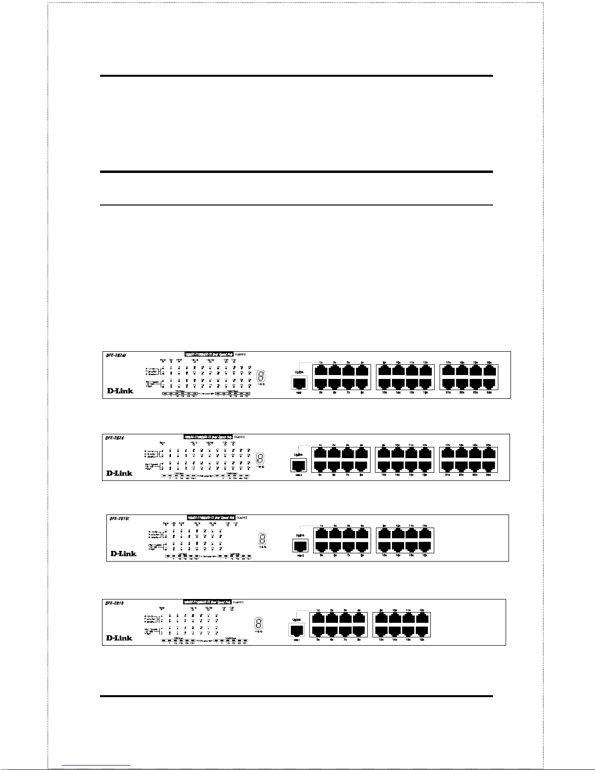
Front Panel
DFE-2624i / DFE-2624ix Front Panel
DFE-2624 / DFE-2624x Front Panel
DFE-2616i / DFE-2616ix Front Panel
DFE-2616 / DFE-2616x Front Panel
Page 20

Dual-Speed Stackable Hubs User’s Guide
Unpacking and Setup8
♦ LED Indicator Panel
Refer to the next chapter,
Understanding Indicators
, for detailed infor-
mation about each of the hub LED indicators.
♦ Twisted-Pair Ports
Use any of these ports to connect stations to the hub. The ports are MDIX Nway ports, which means you can use ordinary straight-through
twisted-pair cable to connect the hub to PCs, workstations, or servers
through these ports, and the speed of the connection will be detected
automatically. If you need to connect to another device with MDI-X
ports such as another hub or an Ethernet switch, you should use a crossover cable, or connect using the Uplink port (described below). For more
information about crossover connection, see the
Crossover Cables
section
on page 112.
♦ Uplink Port
The Uplink port is an MDI port, which means you can connect the hub (or
hub stack) to ano ther de vice with MDI-X p o rts using a n or di nar y straightthrough cable, making a crossover cable unnecessary.
Port 1 and the Uplink port are the same logical port, except their pinouts
are different.
Do not use both Port 1 and the Uplink port at the same
time.
Page 21
Unpacking and Setup 9
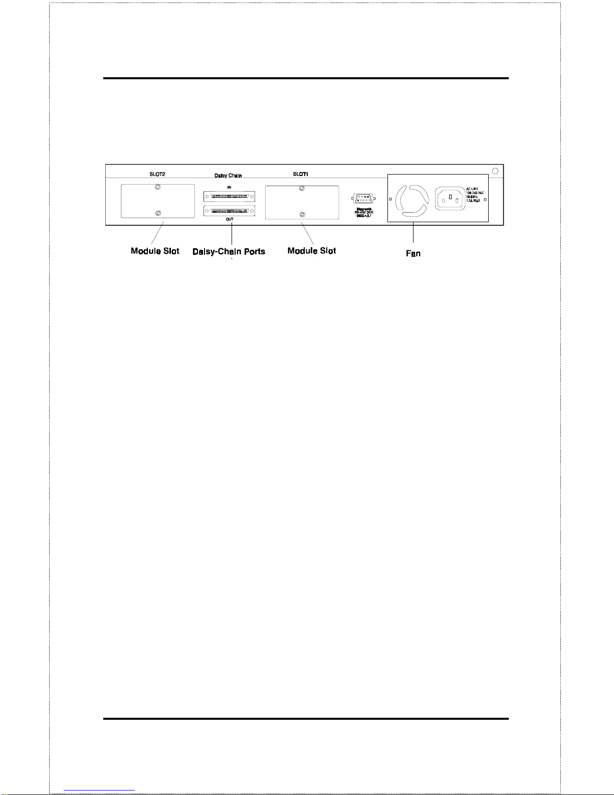
Rear Panel
(Note that the figure shows the rear panel for master models.)
♦ Module Slots
Used to install module options for various kinds of additional connections, as well as the DFE-260S 10Mbps/100Mbps bridge module. (In the
DFE-2616x, DFE-2616ix, DFE-2624x and DFE-2624ix, module slot 1 is
already occupied by the switch module which is standard on these models.)
♦ Daisy-Chain IN Port
When cascading a set of D-Link stackable dual-speed hubs, this port
should be connected to the Daisy-Chain OUT p ort of the previous hub in
the stack (usually placed immediately above it). A cascade of five hubs
can be created in this way. The first and last hubs in the stack use only
one of the daisy-chain ports, while the others use both.
♦ Daisy-Chain OUT Port
Works in conjunction with the Daisy-Chain IN Port (see above). Connect
this port to the Daisy-Chain IN Po rt of the next hub in the stack (usually
placed immediately below it), using the enclosed daisy-chain cable.
♦ Diagnostic (Console) Port -- Master Models Only
Page 22

Dual-Speed Stackable Hubs User’s Guide
Unpacking and Setup10
This 9-pin serial connector is used for connecting a console to the DFE2600 series master hubs for out-of-band management of this particular
hub or the entire stack.
♦ Fan
Provides air circulation and heat dissipation. Be sure to leave adequate
space at the rear of the unit for proper ventilation.
♦ AC Power Connector
For the power cord.
Installing the Hub
Installation
The site where you install the hub stack may greatly affect its performance.
When installing, consider the following pointers:
♦
Install the hub stack in a fairly cool and dry place. See Appendix D,
Specifications
, for the acceptable temperature and humidity operating
ranges.
♦
Install the hub stack in a site free from strong electromagnetic field
generators (such as motors), vibration, dust, and direct exposure to
sunlight.
♦
Leave at least 10cm of space at the front and rear of the hub for ventilation.
♦
Install the hub on a sturdy, level surface that can support its weight, or
in an EIA standard-size equipment rack. For information on rack installation, see the next section,
Rack Mounting.
Page 23
Unpacking and Setup 11
When installing the hub stack on a level surface, attach the rubber feet to the
bottom of each device. The rubber feet cushion the hub and protect the hub
case from scratching.
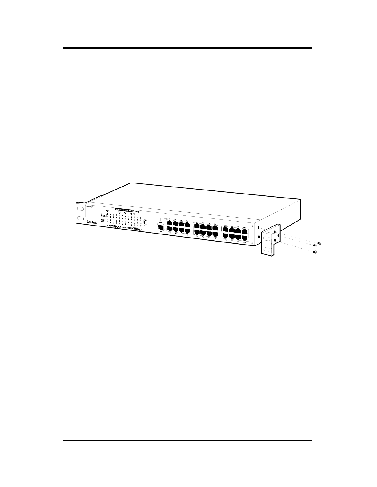
Rack Mounting
The hub can be mounted in an EIA standard-size, 19-inch rack, which can be
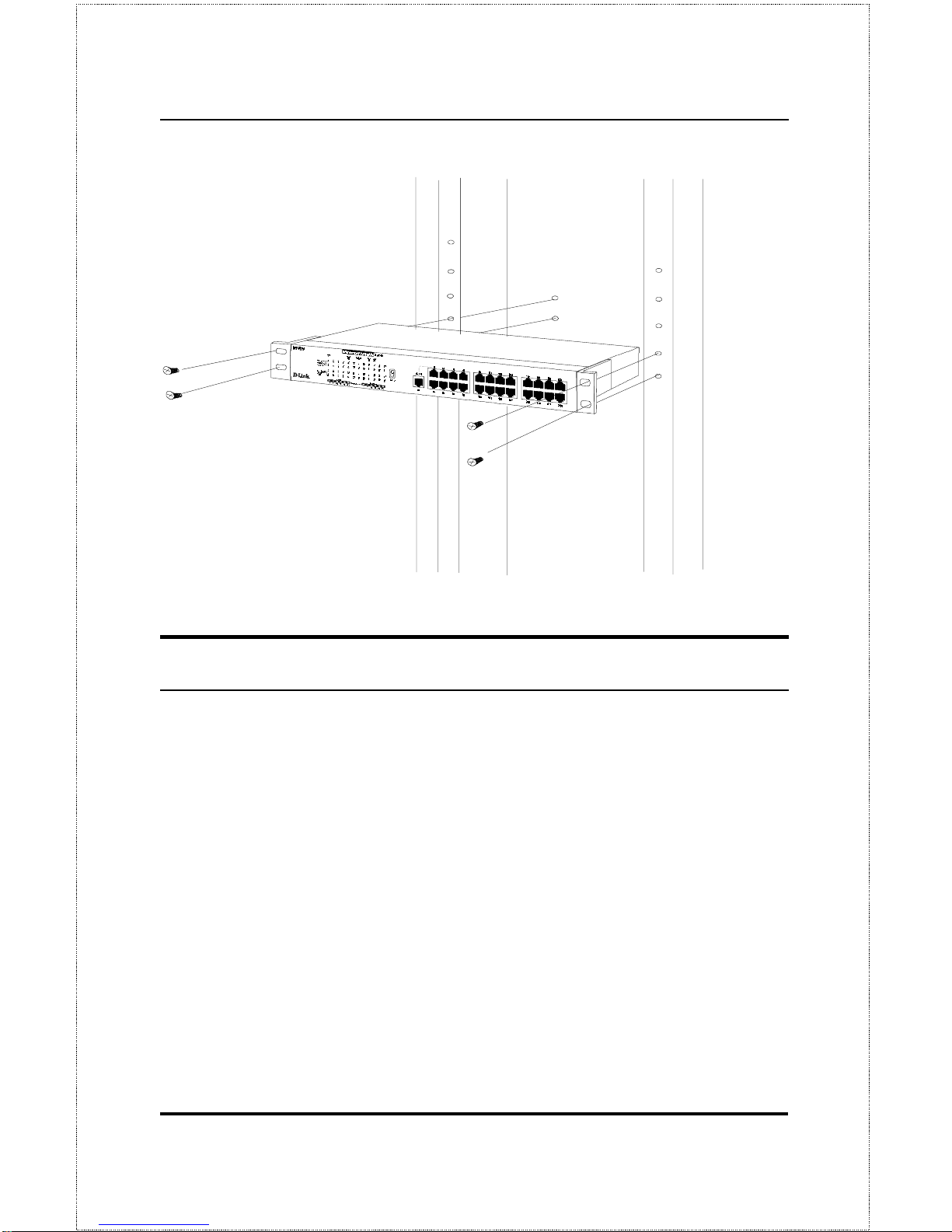
placed in a wiring closet with other equipment. Attach the mounting brackets
at the hub front panel (one on each side), and secure them with the provid-
ed screws.
Then, use screws provided with the equipment rack to mount each hub in the
rack.
Page 24
Dual-Speed Stackable Hubs User’s Guide
Unpacking and Setup12
Replacing the Pow er Supply
The hub comes with a removable power supply for easy replacement. In the
unlikely event that the power supply fails or is damaged, follow the steps
below to replace it:
1.
Disconnect the power cord from the AC outlet.
2.
Disconnect the power cord from its connector on the rear of the hub.
3.
Using a Phillips screwdriver, remove the screws securing the power
supply to release the unit.
4.
Remove the power supply by sliding it out the rear of the chassis. Do
not plug in the power supply when it is outside the chassis! Doing so
could cause personal injury or damage to the power supply.
Page 25

Unpacking and Setup 13
5.
Slide the replacement power supply into the chassis, engaging the
connector carefully.
6.
Attach the power cord to the connector of the power supply and connect the other end of the power cord to the AC supply source.
Page 26

Page 27
Understanding Indicators 15
3
3 U
NDERSTANDING
I
NDICATORS
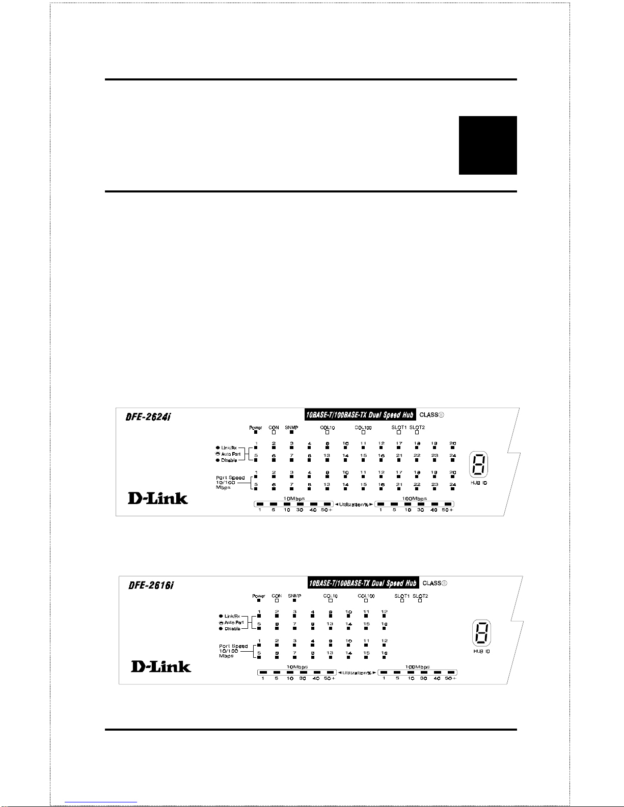
Before connecting network devices to the hub, take a few minutes to look
over this section and familiarize yourself with the front panel LED indicators
of your dual-speed hub, depicted below.
DFE-2624i / DFE-2624ix Indicator Panel
DFE-2616i / DFE-2616ix Indicator Panel
Page 28
Dual-Speed Stackable Hubs User’s Guide
Understanding Indicators16
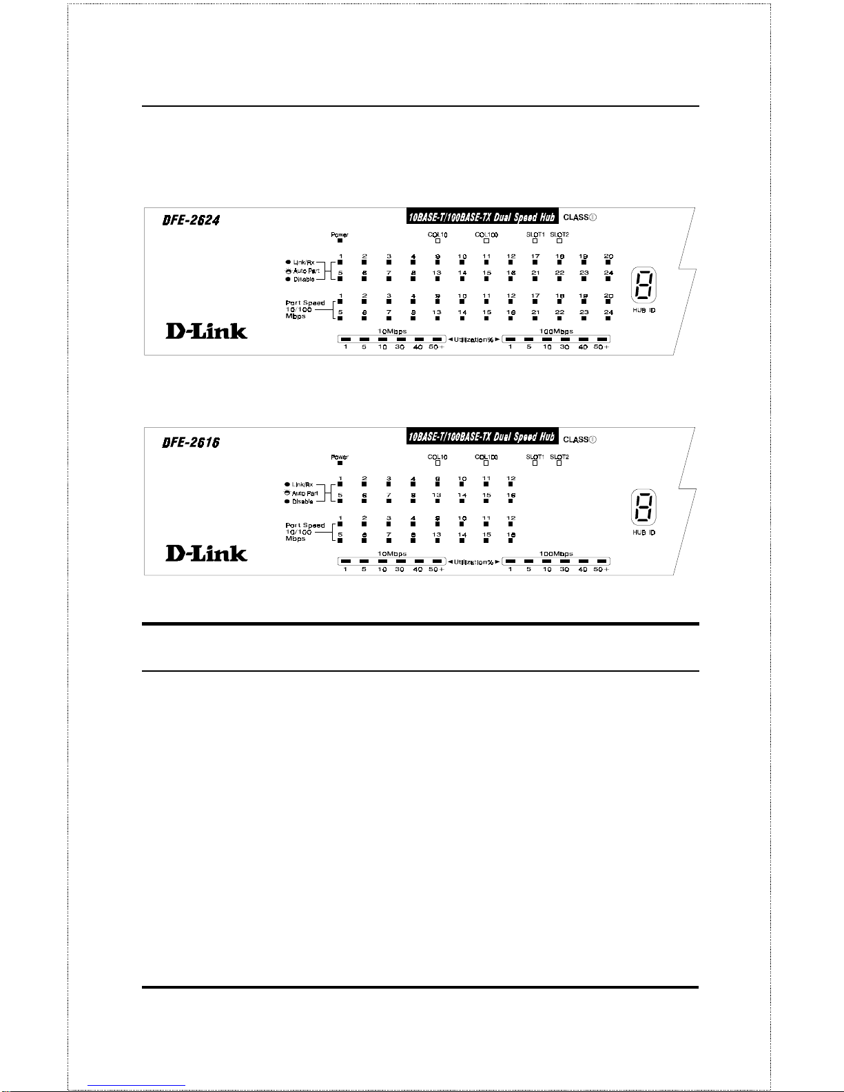
DFE-2624 / DFE-2624x Indicator Panel
DFE-2616 / DFE-2616x Indicator Panel
Hub State Indicators
♦ Power Indicator
This indicator lights green when the hub is receiving power; otherwise, it
is off.
♦ Collision Indicators (COL10 and COL100)
These indicators indicate data collisions on the respective 10Mbps Ethernet or 100Mbps Fast Ethernet segments of the hub. (If several hubs are
stacked or linked together, all of them should detect and indicate the same
collision, since collisions span the entire network segment.) Whenever a
collision is detected, the respective COL indicator will briefly blink amber.
Page 29

Understanding Indicators 17
♦ Segment Utilization % (10Mbps and 100Mbps)
The utilization bar graphs provide a quick reference on the current traffic
load relative to the total available 10Mbps or 100Mbps network bandwidth. The graphs display a measure of the percentage of bandwidth in
use on the respective network segment. All data packets are counted,
whether valid or not.
♦ Hub ID Indicator
The Hub ID readout shows the ID (group) number of the hub within the
hub stack. The first time a hub is powered on within a hub stack, the
master hub in the stack assigns that hub an available ID number which is
then added to each hub factory serial number (encoded on an EEPROM
memory chip). The hub ID is then permanently assigned.
In an unmanaged stack (all slave models), all IDs will read “0” and no
permanent ID assignment is made. In a stack with a master (intelligent)
model, the master hub will detect the other hubs in the stack and automatically assign ID numbers which are then permanently saved by each
hub.
Module Indicators
The two module indicators, SLOT1 and SLOT2, indicate a good link to a
module installed in the respective slot. For the DFE-260S switch module the
indicator will come on when the module is installed. For the DFE-260FX
and DFE-260TX modules, the slot link indicator should light whenever the
module is installed and there is a valid link.
Page 30

Dual-Speed Stackable Hubs User’s Guide
Understanding Indicators18
Port State Indicators
There is one port state indicator for each of the twisted-pair ports on the hub.
Each port LED status indicator reports the port link and activity status,
and shows whether or not the port has been partitioned.
The following describes each indicator and the meaning of each condition:
♦ Link (green)
The indicator of a port lights green when the port is connected to a powered Ethernet or Fast Ethernet station. If the station to which the hub is
connected is powered off, or if there is a problem with the link, the LED
will remain off.
♦ Receive (blinking green)
When information is received on a port, its indicator will blink off briefly.
Upon reception, the data will be transmitted to all other connected ports.
♦ Auto-partition (blinking amber)
The indicator of a port blinks amber when the port is automatically partitioned due to an abnormal network condition.
The hub will temporarily partition a port when too many line errors or too
many collisions are detected on the port. While the segment is automatically partitioned, the port will be isolated from the rest of the network
segment. When the problem is corrected or a valid data packet is received through the port, the port is automatically reconnected.
♦ Disabled (steady amber)
The indicator of a port is orange when the port has been manually disabled. No packet transmission or reception can occur on the port.
Page 31

Understanding Indicators 19
If there is a DFE-2616i, DFE-2616ix, DFE-2624i, or DFE-2624ix master
hub in the stack, then ports can be manually disabled and enabled via the
on-board console interface or via an SNMP-based network management
program such as D -Link D -View Networ k Manage ment Pro gram. Y ou
can choose to partition a po rt even when there is nothing wrong with it,
for example, to prevent a certain device from accessing the network.
SNMP Indicator
(Master models only)
This indicator comes on when the SNMP agent of a DFE-2600 series master
hub is active. In a stack with both a Primary and a Backup Master, the
SNMP LED of the Primary master will be lit and will flash to indicate SNMP
activity. The SNMP LED of the Backup Master will remain off at all times.
Port Speed Indicators
There is also a port speed indicator for each of the twisted-pair ports on the
hub. A port speed indicator should light green when a 100BASE-TX de-
vice is connected to the port, and remain dark if the port is unconnected or if
a 10BASE-T device is connected.
Console Port Indicator (CON)
(Master models only.)
This indicator lights continuo usly under the follo wing two conditions:
Page 32

Dual-Speed Stackable Hubs User’s Guide
Understanding Indicators20
1. A good connection has been established with a console (for example,
a PC or other computer). The diagnostic port of a DFE-2600 series
master hub must be connected to the console's RS-232 serial port using a normal serial cable.
OR
2. The console computer is on-line and connected to the on-board console program either through terminal emulation or a TELNET se ssion.
Refer to Chapter 4,
Making Connections
, for directions on establishing a
connection with the diagnostic port, and Chapter 5,
Master Hub Setup and
Management
, for information about how to use the console interface.
Page 33

Making Connections 21
4
4 M
AKING
C
ONNECTIONS
This chapter discusses how to cascade hubs to create a stack, make connections to the hub twisted-pair and console por ts, and link this hub with other
hubs (or hub sta cks).
Hub Cascading/Building a Stack
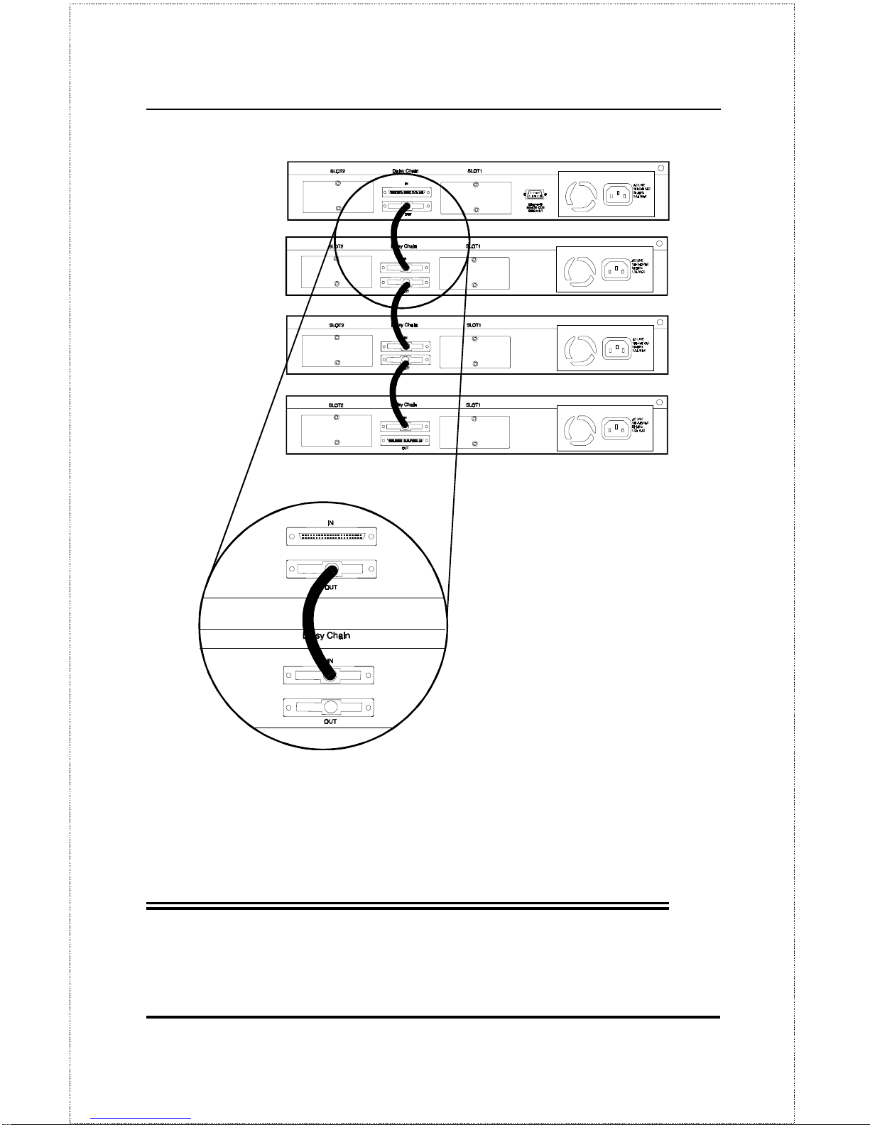
You can stack up to five hubs using the daisy-chain ports located on the rear
of the hub to form one logical hub. In this configuration, the interconnected
hubs constitute a single repeater, providing a maximum of 120 twisted-pair
ports.
Use the provided daisy-chain cable to connect the Daisy-Chain OUT port on
the rear panel of one hub to the Daisy-Chain IN port on the hub below it, as
shown in the figure below. Repeat this procedure for each hub to be included
in the stack.
Each time a new hub is added to the stack, all hub IDs will temporarily revert
to 0, indicating a system reset. After the reset, the hub IDs should return to
their previous values.
Page 34
Dual-Speed Stackable Hubs User’s Guide
Making Connections22
Hubs should not be added to the stack or removed from the stack while the
power is on to any hub in the stack.
Note: Always turn off power to the entire stack be-
fore adding or removing hubs
.
Page 35

Making Connections 23
Connectivity Rules
Ethernet (10Mbps) networks have the following connectivity rules:
♦
The maximum length of a twisted-pair cable segment is 100 meters.
Cabling should be Category 3 or better.
♦
Between any two end-stations in a collision domain, there may be up
to five cable segments and four intermediate repeaters (hubs, hub
stacks, or other repeaters).
♦
If there is a path between any two end-stations containing five segments and four repeaters, then at least two of the cable segments must
be point-to-point link segments (e.g., 10BASE-T or 10BASE-FL),
while the remaining segments may be populated (mixing) segments
(e.g., 10BASE-2 or 10BASE-5).
Fast Ethernet (100Mbps) networks have the following connectivity rules:
♦
The maximum length of a twisted-pair segment (that is, the distance
between a port in the hub to a single-address network device such as a
PC, server, or Ethernet switch) is 100 meters. Cabling and other wiring should be certified as Category 5 UTP or shielded twistedpair(STP).
♦
The maximum diameter in a collision domain is about 205 meters using two Class II hubs (or hub stacks).
♦
Between any two end-stations in a collision domain, there may be up
to three cable segments and two Class II hubs or hub stacks.
Page 36

Dual-Speed Stackable Hubs User’s Guide
Making Connections24
The Diagnostic Port
The diagnostic port o n the rear panel of the master hub is used to establish a
connection with a device to allow in-band or out-of-band management of the
DFE-2600 series hubs stacked with it. The console device connected to the
diagnostic por t can be a terminal (or a computer running terminal-emulating
software) or a PC running TCP/IP TELNE T.
Diagnostic Port Connection
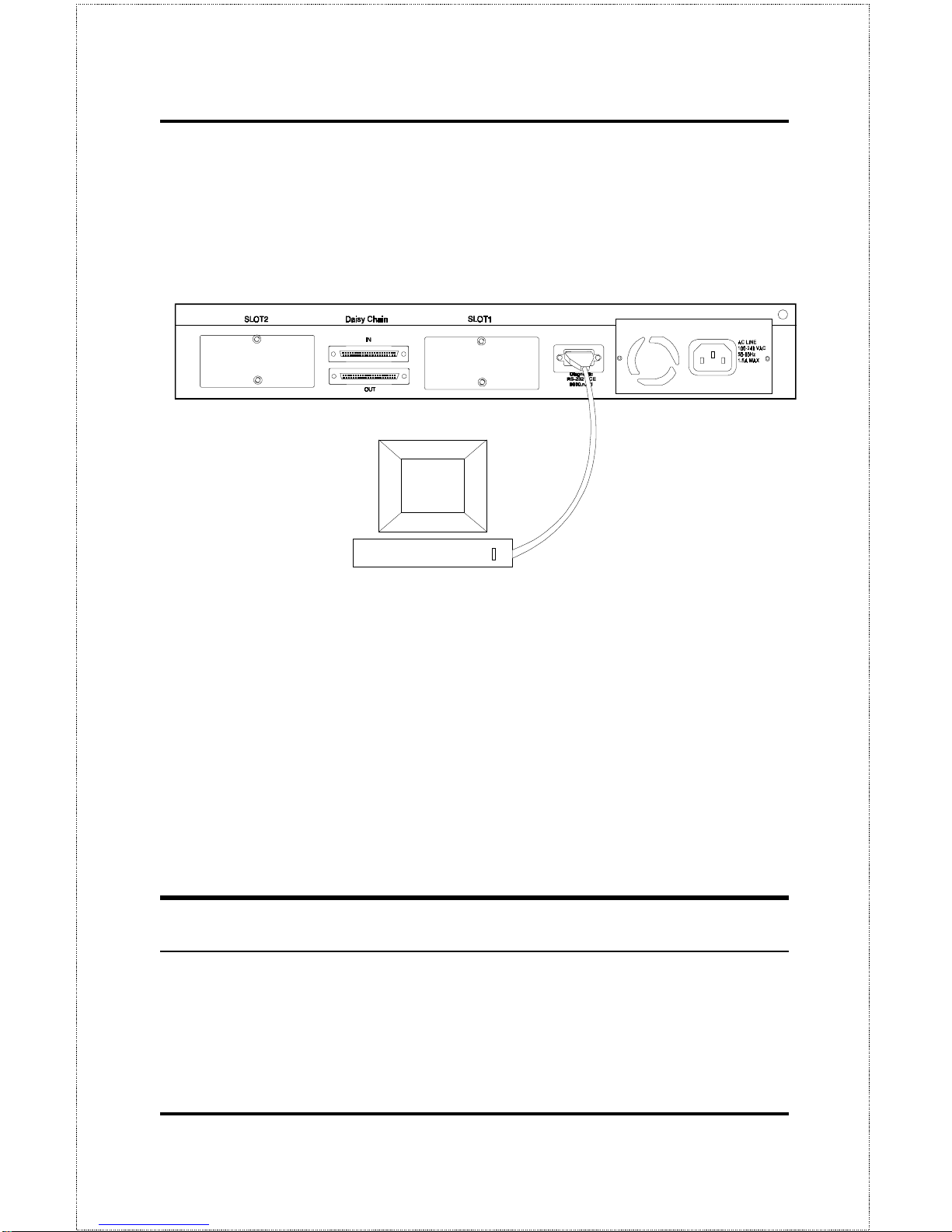
The diagnostic port is an RS-232 DCE interface. To establish a physical line
connection with an RS-232 serial port (DTE) on a PC acting as a console, all
you need is a straight serial cable, as shown in the diagram below. Note that
a DCE-to-DTE connection requires a straight serial cable, not a null-modem
cable.
You can use the diagnostic port on a DFE-2600 series master hub to connect
a VT100-compatible terminal or a computer running an ordinary terminal
emulation program (such as the terminal program included with the Windows
operating system). In all cases, your terminal parameters will need to be set
to:
♦
VT-100/ANSI compatible,
♦
Arrow keys enabled,
♦
9600 baud,
♦
8 data bits,
♦
No parity,
♦
1 stop bit.
You can also access the same functions over a TELNET link. Once you have
set an IP address for your hub (see In-Band Setup Instructions on page 37),
Page 37
Making Connections 25
you can use a TELNET program (in a VT-100 compatible terminal mode) to
access and control the hub. All of the screens are for the most part identical,
whether accessed from the diagnostic port or from TELNET.
A console device can manage a DFE-2600 series master hub operating in
a stack master or stand-alone master role. Use the on-board console program for out-of-band management or D-View (included with DFE-2600
series master hubs) for in-band or out-of-band management. Other
SNMP management software will also work fine.
A console device can only manage a DFE-2600 series hub if it is stacked
with a DFE-2600 series master hub. Use either the on-board console program or an SNMP-based network management program to manage the
stack.
Hub to End-Station Connection
After installing the hub properly, it can support up to sixteen (DFE-2616,
DFE-2616x, DFE-2616i, DFE-2616ix) or twenty-four (DFE-2624, DFE2624x, DFE-2624i, DFE-2624ix) end-station connections. Fast Ethernet
Page 38
Dual-Speed Stackable Hubs User’s Guide
Making Connections26
connections require either a Category 5 UTP cable or an STP cable. These
cables can be up to 100 meters long.
Each Ethernet connection requires a Category 3 or better UTP cable and can
also be up to 100 meters long. It is recommended that you use Category 5
cabling for all connections, in order to make it easier to transition all stations
to 100Mbps.
You can connect any combination of PCs, servers, and other single-address
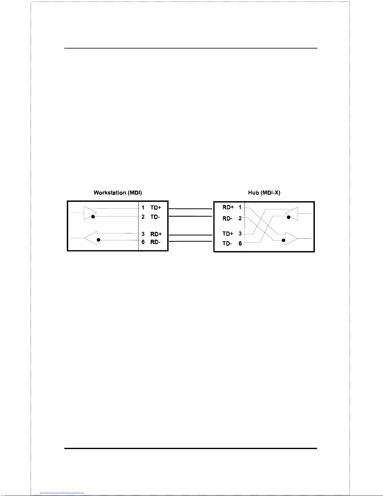
network devices to the twisted-pair po rts using straight-through twisted-pair
cables. These cables should not be crossed over. The following figure illustrates the pin assignments for a straight-through cab le:
When connecting a PC or a server, the system being connected should have
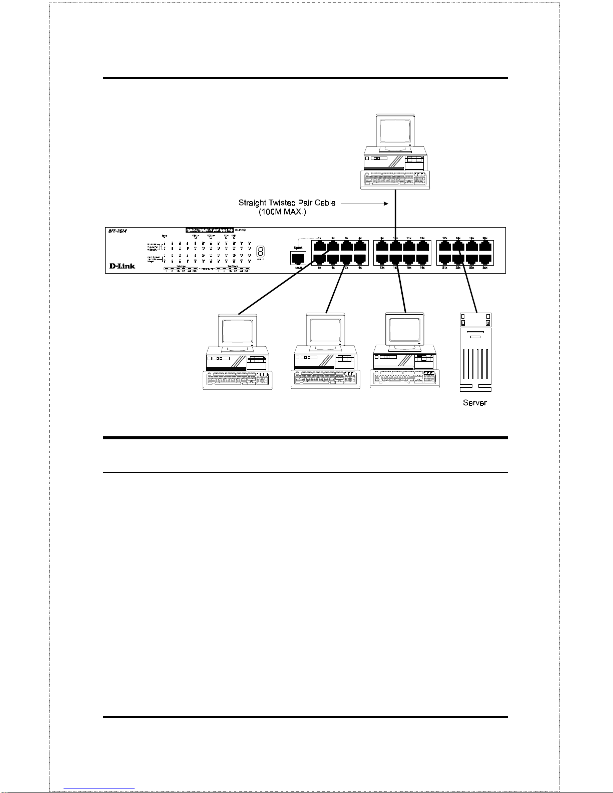
an Ethernet or Fast Ethernet network interface card with a twisted-pair port.
The following figure shows a typical connection between the hub and endstations:
Page 39
Making Connections 27
Hub-to-Hub Uplink
You can link two hubs or hub stacks to each other using any of the normal
twisted-pair (1x - 24x) p orts or the Uplink po rt. Linking hubs using normal
twisted-pair ports requires crossover twisted-pair cables; linking using one
normal twisted-pair port and the Uplink port requires an ordinary straightthrough twisted-pair cable.
The Uplink port is shared with Port 1 and
they cannot be used at the same time.
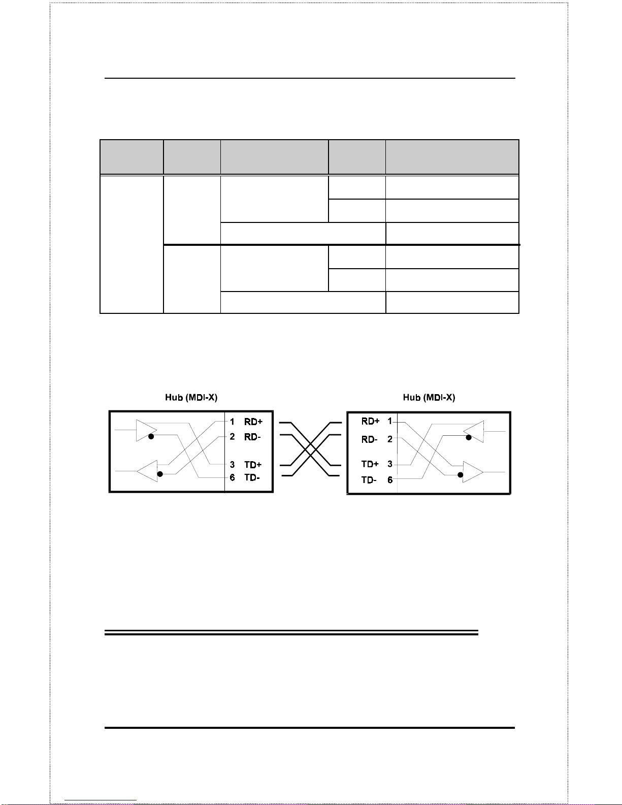
The following table describes different methods of linking hubs:
Page 40
Dual-Speed Stackable Hubs User’s Guide
Making Connections28
DEVICE PORT
USED
DEVICE BEING
CONNECTED
PORT
TYPE
CABL
E TO USE
Hub or
Normal Crossover (X)
Normal
Switch
Uplink Straight-Through (||)
Hub
Server (or PC) Straight-Through (||)
Hub or
Normal Straight-Through (||)
Uplink
Switch
Uplink Crossover (X)
Server (or PC) Crossover (X)
A crossover cable is a twisted-pair cable in which the wires have been
crossed. The figure below shows the pin assignments for an Ethernet or Fast
Ethernet crossover cable:
NOTE:
The port 1 1X jack shares its circuitry with the
Uplink
jack. If you connect a hub to the
Uplink
jack, you cannot plug anything into the
1X
jack. And the reverse is also true; if any-
thing is plugged into the
1X
jack, the
Uplink
jack cannot be used.
When uplinking two dual-speed or Fast Ethernet hubs or hub stacks in this
fashion, the maximum distance between any two end-stations in a collision
domain is 205 meters. If the length of the longest hub to end-station connec-
Page 41

Making Connections 29
tion on each hub is 100 meters, then the hub-to-hub connection is limited to 5
meters. However, if the longest hub-to-end-station connection is less than
100 meters, then the hub-to-hub connection can be up to 100 meters long.
Almost any variation of cable lengths are possible as long as each segment is
shorter than 100 meters and the total network diameter does not exceed 205
mete rs.
The DFE-2600 are dual-speed hubs capable of operating at both 10Mbps
(Ethernet) and 100Mbps (Fast-Ethernet). The connection speed is automati-
cally determined using the built-in NWay auto-detection technology, which
will always choose the fastest possible connection speed. Thus, if a DFE2600 series hub or hub stack is linked through a twisted-pair or Uplink p ort
to another dual-speed or Fast Ethernet hub or hub stack, the connection speed
will be 100Mbps, which will limit the total number of hubs or hub stacks in
the network to two and the total network diameter to 205 meters. If a DFE2600 series hub or hub stack is linked through a twisted-pair or Uplink p ort
to a 10Mbps (only) Ethernet hub or hub stack, the connection speed will be
10Mbps, the maximum number of hubs/stacks in the network will be four,
and the total network diameter can be 500 meters maximum (assuming the
entire network is composed of twisted-pair wiring).
Since the DFE-2600 series hubs are dual-speed hubs containing two separate
repeaters, they can be part of a Fast Ethernet collision domain and a normal
Ethernet collision domain at the same time, counting as one repeater in each.
Optional Module Connections
There are three optional modules that may be added to any of the DFE-2600
series hubs. Each hub can accommodate two modules. Each of the modules
offers a different additional network interface that allows for greater flexibility in how these hubs may be used in a network.
The sections that follow provide a brief overview of the module and basic
instructions on any settings and indicators.
Page 42
Dual-Speed Stackable Hubs User’s Guide
Making Connections30
Module Installation
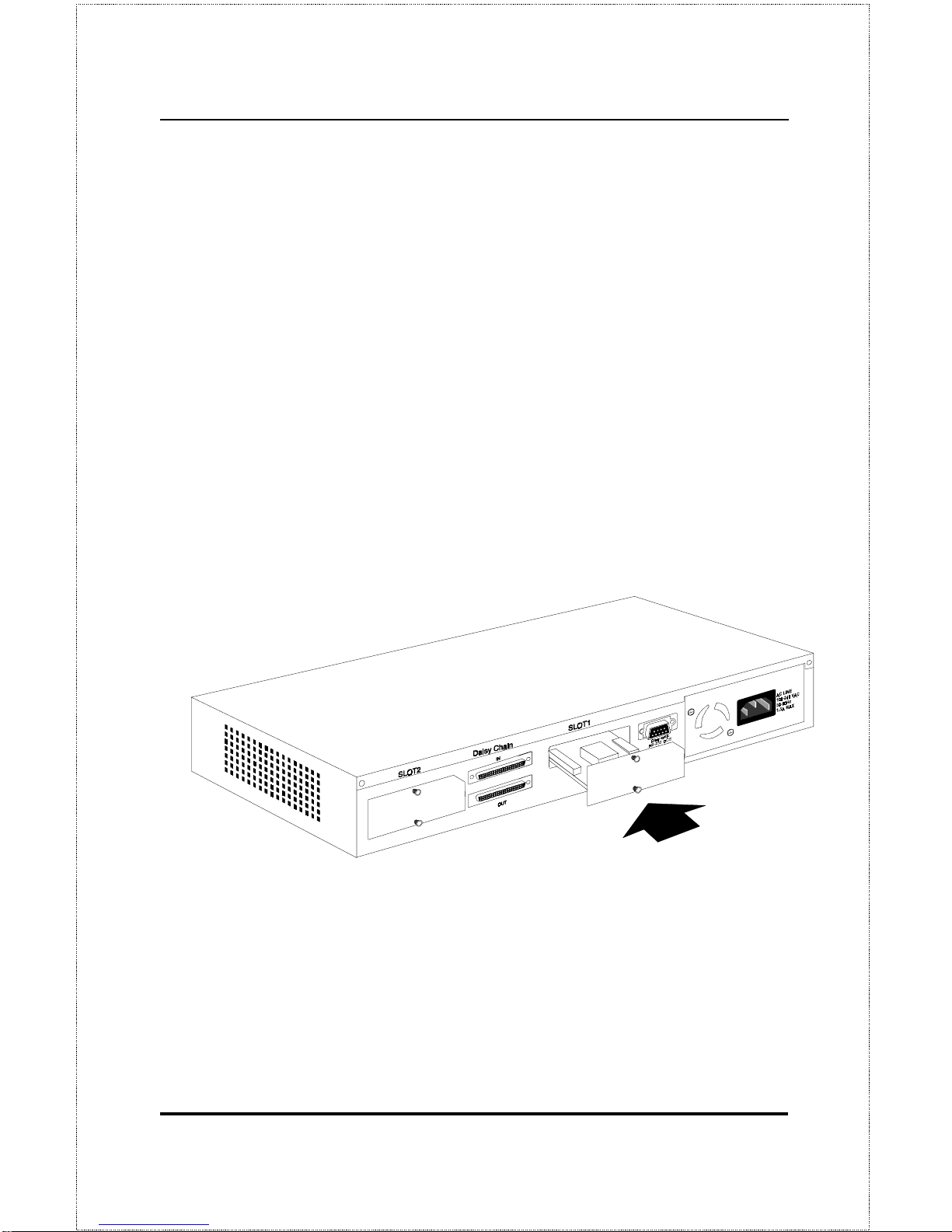
The installation procedure for each module is the same. Additional information about each module is provided below.
To install any of the modules:
1. Locate one of the module slots in the hub rear panel. (Note that the
DFE-260S module can only be installed in Slot 1 - the center slot.)
2. Using a screwdriver, undo the two screws and remove the dust cover on
the module slot.
3. Holding the module component-side up and connector-side in, gently
slide the module along the guides and seat it in the internal connector.
4. Using a screwdriver, replace the two screws and tighten until snug.
We recommend that you retain the dust cover in case you need to remove the
module for an extended period sometime in the future.
Page 43

Making Connections 31
Switch Module (DFE-260S)
The DFE-260S switch module is used to allow interconnection between the
10Mbps and 100Mbps segments in the hub or hub stack. Each hub stack
should have one DFE-260S module (such as the one included in the DFE2616x, DFE-2616ix, DFE-2624x or DFE-2624ix) to allow 10Mbps and
100Mbps stations to intercommunicate.
Note that the DFE-260S module
can only be installed in Slot 1 – the center slot
. Also, the presence of
switch modules and their operational status can be viewed on the etwork
Monitoring – Bridge Information” screen.
NOTE:
In a stack containing a DFE-2616i, DFE-2624i,
DFE-2616ix, or DFE-2624ix intelligent master
hub, more than one DFE-260S switch module
may be used to provide increased reliability
through redundancy. The software management agent can control the DFE-260S
modules to provide link redundancy and prevent network loops but only when multiple
modules are installed in hubs on the primary
master segment.
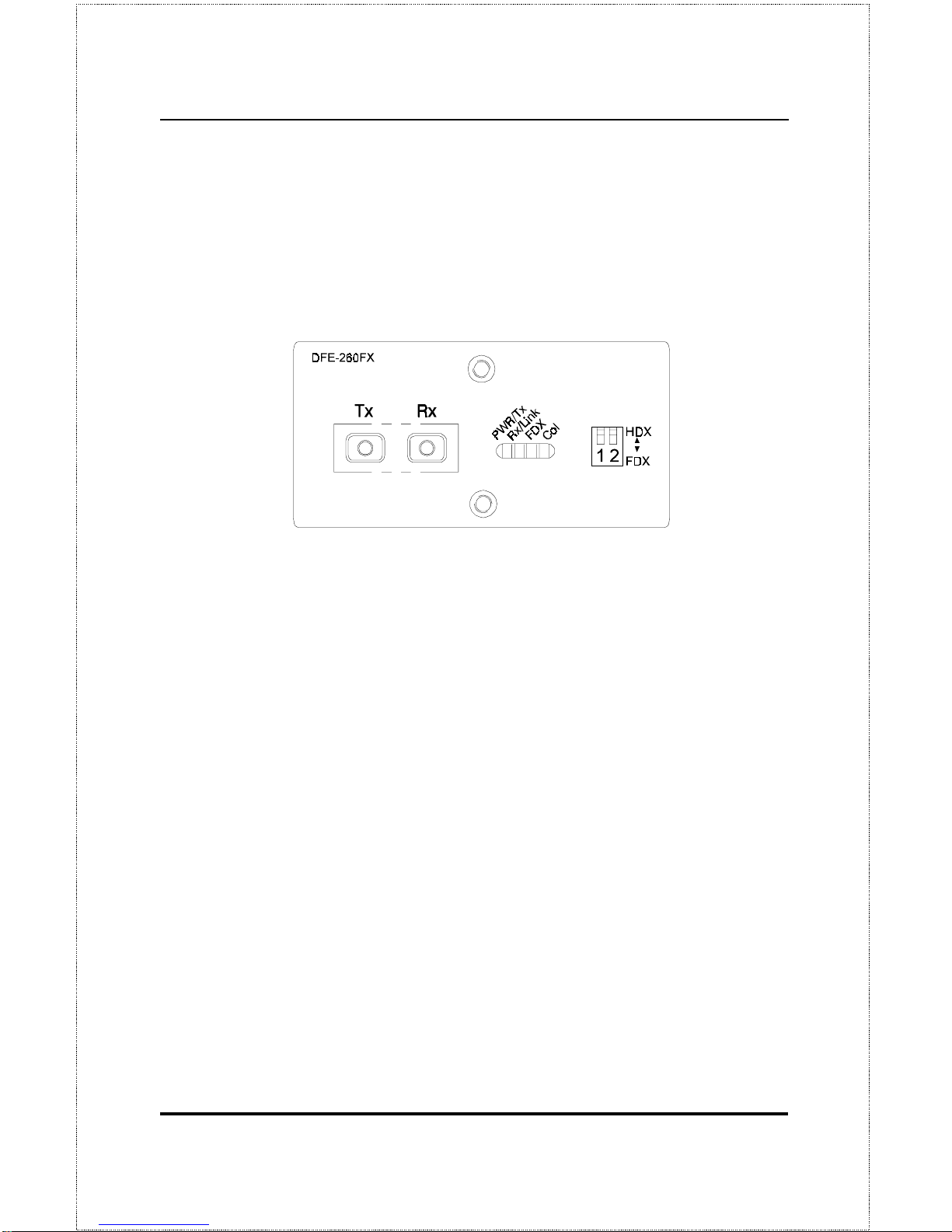
Fiber Optic Module (DFE-260FX)
The Fiber Optic module provides a standard Fast Ethernet 100BASE-FX
fiber optic connector. A fiber optic connection of this kind is particularly
useful for creating a link between two DFE-2600 series hub stacks, placing
them in separate collision domains. A link of this sort eliminates the need for
an external switch to divide stacks into separate domains. Dividing the stacks
into separate collision domains overcomes the Fast Ethernet two-repeater
limitation, and effectively doubles overall bandwidth.
The Fiber Optic module includes the following LED indicators:
Page 44
Dual-Speed Stackable Hubs User’s Guide
Making Connections32
• Power/Tx
his LED is lit when the hub is on and blinks when packets
are being transmitted by the module.
• Link/Rx
his LED is lit when the fiber optic ports are properly connect-
ed to a powered-on device and blinks when packets are being received
by the module.
• Collision
his LED blinks when there are packet collisions on the fiber
optic link.
• FDX
his LED is lit when the fiber optic port is set for Full Duplex
transmit and receive. When the LED is off, the fiber optic port is in Half
Duplex mode.
The duplex mode DIP switch allows you to set the fiber optic lines to Full
Duplex mode operation. Only the right-hand switch (number 2) is active.
Use it to set the duplex mode.
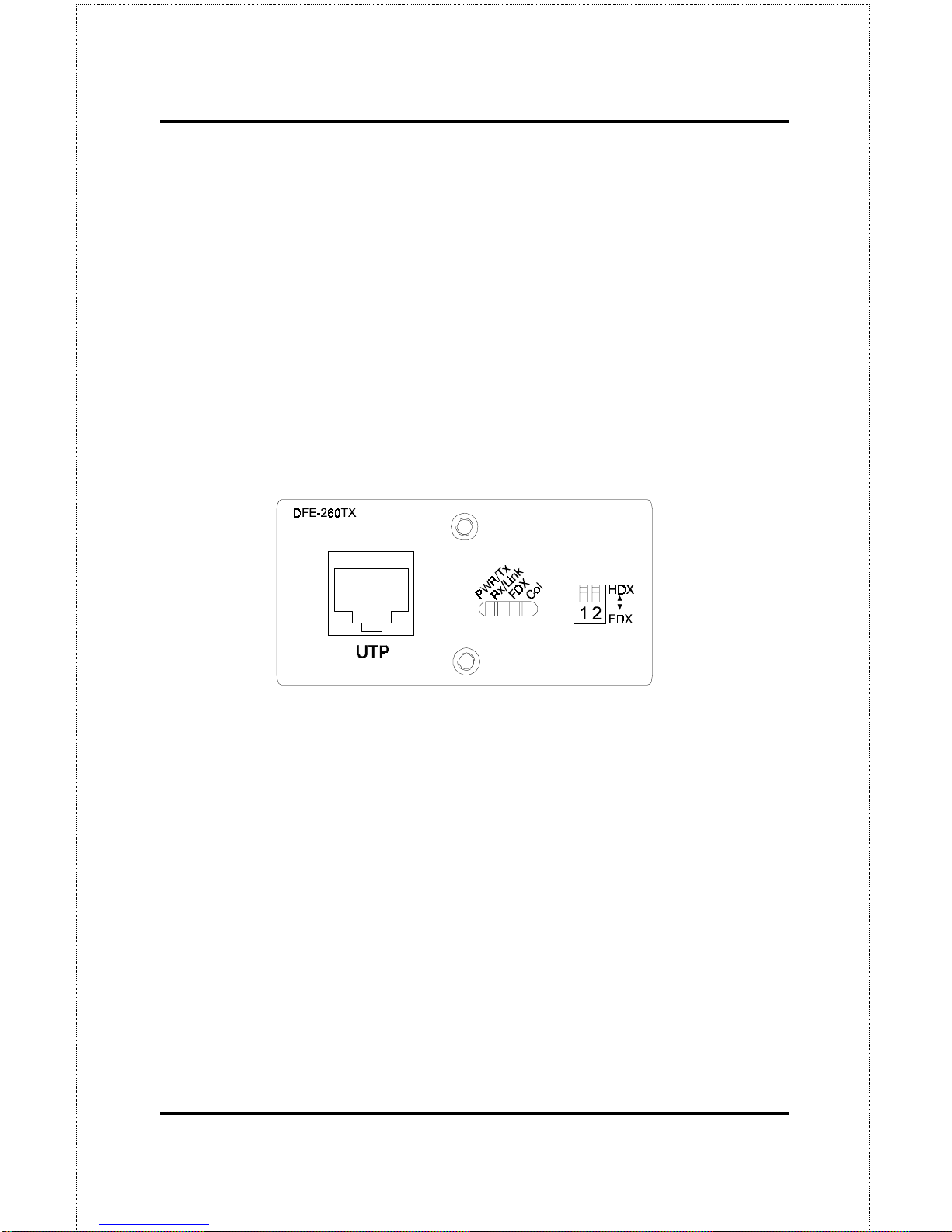
Fast Ethernet Module (DFE-260TX)
The Fast Ethernet module provides one additio nal twisted-pair Fast Ethernet
connection. A twisted-pair connection of this kind is particularly useful for
creating a link between two DFE-2600 series hub stacks, placing them in
separate collision domains. A link of this sort eliminates the need for an external switch to divide stacks into sepa rate domains. Dividing the stacks into
separate collision domains overcomes the Fast Ethernet two-repeater limitation, and effectively doubles overall bandwidth.
Page 45
Making Connections 33
The Fast Ethernet module uses a MDI-X connector (not a straight MDI) and,
therefore, a crossover cable must be used when connecting the module to
another module (and under most other circumstances). See Appendix A for
pinout information.
The Fast Ethernet module includes the following LED indicators:
• Power/Tx
his LED is lit when the hub is on and blinks when packets
are being transmitted by the module.
• Link/Rx
his LED is lit when the port is properly connected to a pow-
ered-on device and blinks when packets are being received by the
module.
• Collision
his LED blinks when there are packet collisions on the mod-
ule line.
• FDX
his LED is lit when the port is set for Full Duplex transmit and
receive. When the LED is off, the port is in Half Duplex mode.
NOTE: Because the DFE-260TX module port is an
NWay UTP port, once the hub is pow ered on,
it will automatically detect the duplex and
speed modes of any device connected to it.
The DIP switch may then be set to force the
duplex mode into a particular state. After the
DIP switch is set, the DFE- 260TX will only op-
Page 46

Dual-Speed Stackable Hubs User’s Guide
Making Connections34
erate at 100Mbps in the duplex mode selected.
The duplex mode DIP switch allows you to set the por t to Full Duplex mode
operation. Only the right-hand switch (number 2) is active. Use the DIP
switch to set the duplex mode.
Page 47
Master Hub Setup and Management 35
5
5 M
ASTER
H
UB
S
ETUP
AND
M
ANAGEMENT
The DFE-2616i, DFE-2616ix, DFE-2624i, and DFE-2624ix master hubs
(hereafter and elsewhere referred to as, FE-2600 series master hubs”)
provide an on-board console program that allows you to set up and control all
DFE-2600 hubs stacked with it. This program can be accessed either with an
ordinary terminal (or terminal emulator) or over the network using the
TCP/IP TELNET protocol. You can use this program to perform many basic
network management functions.
The console program also allows you to prepare the hub for management
using D-View or another SNMP-based network management system. This
chapter describes how to use the console program to access the hub, change
its settings, and monitor its operation.
Note that if you want to manage the hub in-band you need to follow the instructions in the first section of this chapter to prepare the hub for in-band
management. If you need infor mation about connecting a console device to
the diagnostic port for out-of-band management, see the relevant sections of
Chapter 4.
Page 48

Dual-Speed Stackable Hubs User’s Guide
Master Hub Setup and Management36
Navigation and Conventions
This section de scribes how to navigate the master hub management software
and the conventions used in that software.
Navigation
The Tab keys move the cursor from field to field. Note that they are unidirectional (i.e., Shift-Tab is not a functional combination). Up and Down
arrow keys allow cursor movement between some fields.
The Spacebar is a toggle switch for all variables that can be changed but
wherein possible values are preset.
The Delete and Backspace keys remove entered text as in most software
packages.
Pressing Ctrl-r refreshes the current screen.
Screen Conventions
Fields that cannot be changed are preceded by a colon (“:”).
Toggle changed fields are surrounded by angle brackets <>.
Variables with values that must be keyed-in are surrounded by square brack-
ets [ ].
Uppercase letters are reserved for command items such as SAVE or
LOGOFF. Highlighting the item and pressing Enter activates the command.
Note: Both the navigation and screen conventions
information can be obtained under HELP in
the system management software.
Page 49

Master Hub Setup and Management 37
In-Band Setup Instructions
This section describes ho w to setup the hub fo r in-b and management.
Getting Started
Physically install and cascade the hubs and power on the hub stack according
to the directions in other parts o f this manual. At this point, the hub stack is
ready for use as an ordinary unmanaged repeater.
The master hubs in the series come without IP addresses assigned (IP =
0.0.0. 0). If you want to manage your hubs using a network management system, you will have to assign an IP address to the primary master hub, and if
applicable, the backup master. IP addresses must be assigned to the master
hubs before any type of management is possible. After an IP address is set the
first time, it can later be change d by using a network management program.
There are two ways to initially assign an IP address to a master hub; using
BootP and by using a Console conne ction to the Diagnostic Port.
Assigning an IP Address Using BOOTP
If your Fast Ethernet network has a BOOTP (BOOTstrap Protocol) server,
you need only add the hub Ethernet (MAC) address (which is printed on a
sticker on the bottom of the hub, or which you can determine using the master
hub console interface), IP address, subnet mask, and boot configuration filename to your BOOTP server configuration tables. The boot configuration
filename field of the hub BOOTP configuration table should contain the
filename of a DFE-2600 series master hub boot configuration file accessible
on your local TFTP (Trivial File Transfer Protocol) server. This file can be
empty. For more detailed information about the boot configuration file contents, see
Appendix C : Boot Configuration File
of this manual.
Assigning an IP Address Using the Diagnostic Port
To assign an IP address to a hub manually,
Page 50

Dual-Speed Stackable Hubs User’s Guide
Master Hub Setup and Management38
1.
Connect a VT-100 compatible terminal or a personal computer running a VT-100 compatible terminal emulation program to the DB-9
console port at the rear of the master hub. The cable should be an ordinary RS-232C cable. The terminal communications parameters
should be set to 9600bps, 8 bits, no parity, and 1 stop bit.
2.
Turn on hub.
3.
As the hub begins its boot process, hit Control-C to enter the PROM
System Menu.
4.
Choose TCP/IP Parameters Configuration, and enter a valid IP address, network mask, and (optional) gateway router IP address.
Choose SAVE and press
<Enter>
to let the changes take effect, and
then choose EXIT.
5.
If you will be using TFTP to download a hub configuration file,
choose Software Update and toggle the Software Update Control to
Enable using the Space Bar. Again, choose SAVE and then EXIT.
6.
Choose Execute Bootstrap to restart the hub.
If you are using a backup master hub, reconnect the RS-232C cable to the
backup master and repeat the same procedures listed above (the backup
master must have a different IP Address than the primary master).
You are now ready to use your DFE-2600 series hub stack, and to manage it
from a network management station on your network. See the
Stack Man-
agement User Guide
for more information about how to manage the stack
using the D-View Network Management Program.
Backup Master Function
Within a DFE-2600 series hub stack, in addition to a master hub for management purposes (the primary master), a standby backup master can also be
Page 51

Master Hub Setup and Management 39
installed. If a hub stack has two master units, the master unit powered-on
first or the unit which is higher in the stack will manage the stack and be
designated the rimary Master.” Master hubs in the series include a built-in
contention algorithm which determines which hub will manage the stack and
which will operate in standby mode. If, during power-on, the two master
hubs in the stack both attempt to initialize as the Primary Master, this collision will result in an automatic stack reset indicated by all hub ID numbers
changing to 0 tempora rily. If the cur re ntly managing hub fa ils or is po wered off, the standby master will take over management of the hub stack.
Segmenting Hubs
Switching hub technology has made it more common to segment local area
networks into smaller pieces to reduce congestion. Segmenting makes it
easier to balance network loads, since a smaller number compete for the
bandwidth available.
A hub stack makes network management convenient, but too many stations
on a single network segment may give slow respo nse at peak network loa ds.
Therefore, this hub series provides a way to segment hubs from the stack into
their own collision domains. Segmenting hubs can be accomplished with a
simple management command and does not require any hardware or wiring
changes.
Though the hubs continue to be cascad ed together a nd are managed as a single unit, each hub can either be a part of the collision domain of the rest of
the stack, or can be sep arated into its own network segment. These sep arate
segments can be bridge d by conne cting them through a co mpatible switching
hub.
Page 52
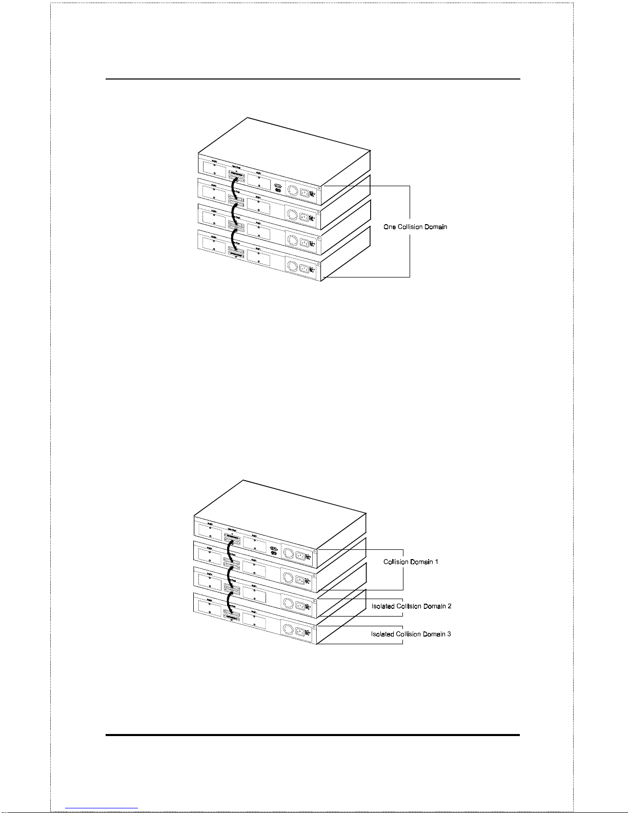
Dual-Speed Stackable Hubs User’s Guide
Master Hub Setup and Management40
The figure above shows an unsegmented hub stack. All hubs in the stack are
in the same collision domain because they are connected together thr ough the
daisy-chain ports.
The figure below shows a stack divided into three separate collision do mains.
Hubs three and four are isolated from the main segment (collision domain
one) using the hub's segmentation capability, putting them into their own
isolated collision domains two and three respectively. A switch, bridge or
router can be used to connect the three collision domains so that traffic can
pass between them, yet keeping them isolated to reduce congestion on each
segment.
Page 53

Master Hub Setup and Management 41
For information ab out segmenting hubs using the network management module for the hub, see the ub Stack Management: Controlling Hubs in the
Hub Stack” section later in this chapter.
NOTE: Hub segmentation is controlled by the master
hub. When the master hub completes its initialization, it will restore any prior segmentat ion
of the hubs. Therefore, if you are using a
switch or bridge to join different segments, be
sure to enable the IEEE 803.1d Spanning Tree
Protocol to prevent temporary network loops
Logging in to the Hub Console
The DFE-2600 series master hubs support user-based security that allows you
to prevent unauthorized users from accessing the hub or changing its settings.
This means that before you can access the functions of the hub, you will need
to first log into the hub, p roviding a password. This section tells how to log
onto the hub, and how to change your password.
Logging In
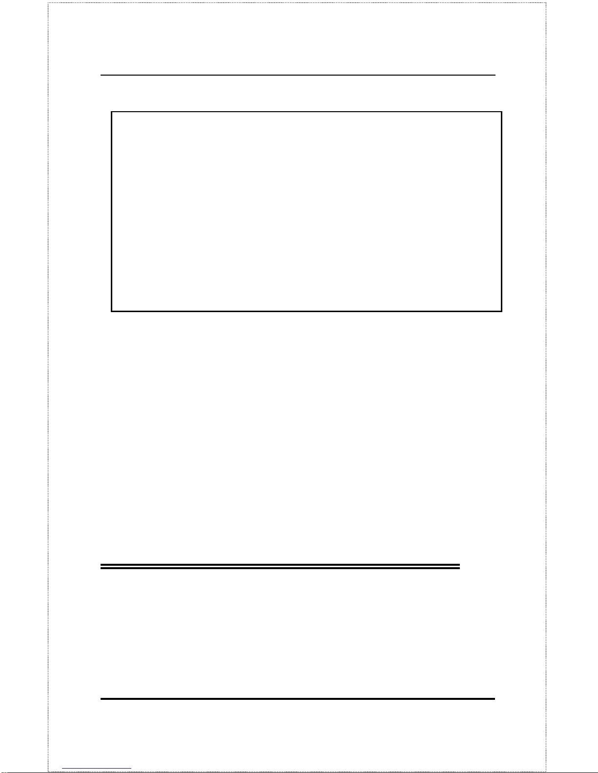
When you first connect to the hub, it will display the login screen:
Page 54
Dual-Speed Stackable Hubs User’s Guide
Master Hub Setup and Management42
DFE-2600 Dual speed Stackable Hub Telnet Remote Management Ver0
Copyright(C) 1995-96 D-Link Corp.
User Name [ ]
Password [ ]
OK CLOSE CONNECTION
To log in, complete these steps:
1.
Type in your user name and press
<Enter>.
2.
Type in your password and press
<Enter>.
3.
With the cursor on the OK selection, press
<Enter>.
NOTE:
When the hub is shipped, the default user
name is
D-Link
, and the default password is
also
D-Link
. You will need to use this user
name and password when you first set up your
hub or if you use the Factory Reset NVRAM to
Default Value menu selection.
Change this
user name and password to protect the security of your hub.
There are two levels of user privilege:
Super User
and
General User
. The
default user (
D-Link
) has
Super User
privileges. Some functions available to
Super Users
are not available to
General User
s. The main menu below is the
menu for
Super Users:
Page 55

Master Hub Setup and Management 43
DFE-2600 Stackable Hub - Main Menu
System Configuration
TCP/IP Parameters Configuration
Network Monitoring
Out-of-Band/Console Configuration
User Account Change
SNMP Trap Manager Configuration
SNMP Manager Configuration
System Reset
Software Update
Factory Reset NV-RAM to Default Value
LOGOFF
Changing Your Password
To change your user password, follow these steps:
1.
Choose
User Account Change
from the main menu.
2.
Select
Change Password.
The following screen will be displayed:
Page 56

Dual-Speed Stackable Hubs User’s Guide
Master Hub Setup and Management44
DFE-2600 Stackable Hub - User Acco unt Change : Change Password
User Name [ ]
Old Password [ ]
New password [ ]
Confirm Password [ ]
HELP SAVE EXIT
3.
Type in your user name and press
<Enter>.
4.
Type in your old password and press
<Enter>.
5.
Type in the new password you have chosen, and press
<Enter>.
Type in the same new password again in the next blank space to verify
what you typed.
6.
Choose
SAVE
to put the new password into effect.
7.
Choose
EXIT
to exit this screen.
This method can also be used by a
Super User
to change another user
password.
Page 57

Master Hub Setup and Management 45
Setting Up the Master Hub
This section describes ho w to set the hub conso le parameters for the various management options it supports. Note that the hub can be managed in-
band or o ut-of-band, and either through the built-in console p rogram, or using an SNMP-management program such as D-View.
TCP/IP Settings
The hub needs to have an IP add ress assigned to it so that the ne twork management system or TELNET client can communicate with it over the
network. The T CP/IP P arameters Co nfiguration Menu allo ws you to change
the settings for the two different interfaces used by the hub: the internal Fast
Ethernet interface used for in-band communication, and the SLIP interface
used through the di agnostic port for out-of-band communication.
Note: if you need to set an IP address so that you can access the hub console
through a network, see the first section of this chapter.
Saved changes to any of the fields on this menu take effect the next time the
system is restarted. Fields that can be set include:
♦ Interface
. This parameter displays the type of interface the hub will use
for management communications.
♦ IP Address
. This parameter determines the IP address used by the
hub for receiving SNMP and TELNET messages. Should be of the
form xxx.xxx.xxx.xxx, where each xxx is a number (represented in
decimal) between 0 and 255. This address should be a unique address
on the network assigned to you by a network administrato r. T he same
IP address is shared by both the SLIP and Ethernet network interfaces.
♦ Subnet Mask
. This parameter sets the subnet mask that determines
the level of the subnet that the hub is on. Should be of the form
xxx.xxx.xxx.xxx, where each xxx is a number (represented in decimal)
between 0 and 255. If no subnetting is being done, the value should
Page 58
Dual-Speed Stackable Hubs User’s Guide
Master Hub Setup and Management46
be 255.0.0.0 for a Class A network, 255.255.0.0 for a Class B network, and 255.255.255.0 for a Class C network.
♦ Default Gateway
. This parameter specifies the IP address for a
gateway or a router where frames with destinations outside the current
subnet should be sent. If your network is not part of an internetwork,
or you do not want the hub to be accessible outside your local network, you can leave this field blank.
♦ Send BOOTP Request Upon Power Up
. This parameter determines
whether or not the hub should send out a BOOTP request when it is
powered up. The BOOTP protocol allows IP addresses, network
masks, and default gateways to be assigned from a central BOOTP
server; if this option is set to es,” the hub will first look for a
BOOTP server to provide it with this information before using local
settings.
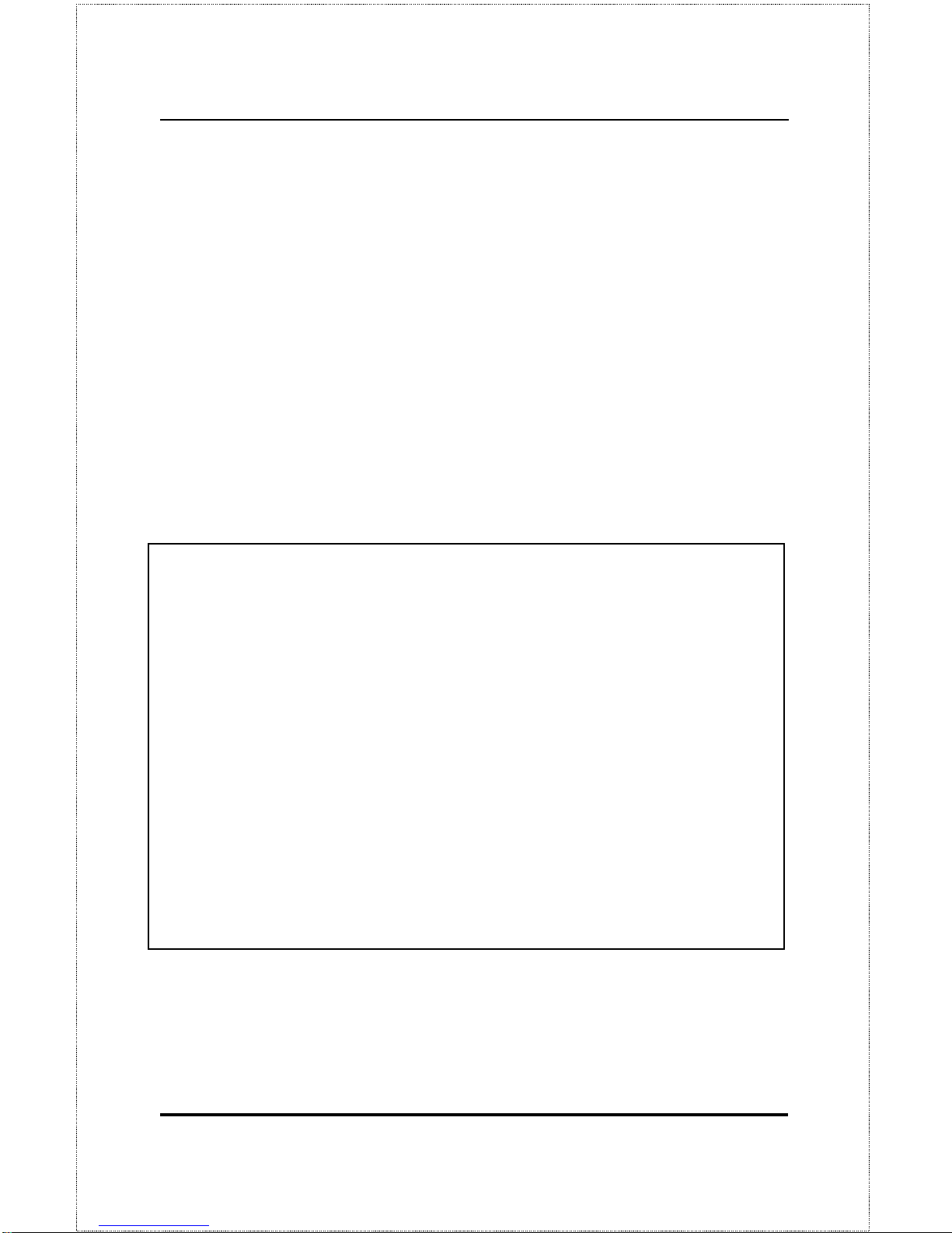
DFE-2600 Stackable Hub - TCP/IP Parameters Configuration Menu
Interface #<1 Media Type: Ethernet>
Current Setting
IP Address: 210.68.85.51
Subnet Mask: 255.255.255.0
Default Gateway: 210.68.85.126
System Restart Setting
IP Address [210.68.85.51 ]
Subnet Mask [255.255.255.0 ]
Default Gateway [210.68.85.126 ]
Send BootP Request Upon Power Up <No >
HELP SAVE EXIT
The default setting for all TCP/IP variables is 0 . 0.0.0.
Page 59

Master Hub Setup and Management 47
Out-of-Band Management and Console
Settings
You can use the Out-of-Band/Console Setting menu to choose whether to use
the hub RS-232 serial port for console management or for out-of-band
TCP/IP communication using SLIP, and to set the baud rate used for SLIP
communications.
The following fields can be set:
♦ System Restart Out-of-Band Baud Rate
. This parameter determines the serial port baud rate that will be used the next time the hub is
restarted. It applies only when the serial port is being used for out-ofband (SLIP) management; it does not app ly when the port is used as a
console port. Available speeds are 1200, 2400, 9600, and 19200 bits
per second.
♦ Out-of-Band Dial Up Phone Number
. This information is stored as
a reference for the benefit of the system manager and does not cause
the hub to dial out.
♦ System Restart Serial Port Setting
. This parameter determines
whether the serial port should be used for out-of-band (SLIP) management or for console management, starting from the next time the
hub is restarted. It can be set to either onsole” or ut-of-Band.”
Page 60

Dual-Speed Stackable Hubs User’s Guide
Master Hub Setup and Management48
DFE-2600 Stackable Hub - Out-of-Band/Console Setting Menu
Out-of-Band Setting Console Setting:
Protocol: SLIP
Baud Rate: 9600 Baud Rate: 9600
Character Size: 8 Character Size: 8
Stop Bit: 1 Stop Bit: 1
System Restart Out-of-Band Baud Rate
<9600 >
Out-of-Band Dial Up Phone Number
[]
Current Serial Port Set ting: Console
System Restart Serial Port Setting <Console >
HELP SAVE EXIT
Software Update on Boot
The hub is capable of obtaining its boot-time configuration information, as
well as updated versions of its internal firmware, using TFTP (the Trivial File
Transfer Protocol) and BOOTP (the BOOTstrap Protocol). You can use the
Software Update menu to control this feature.
The fields you can set on this menu are:
♦ Software Update
. This parameter determines whether or not the hub
will try to look for the configuration file over the network. If set to
Disable, the parameters below become irrelevant.
♦ Software Update M ode
. This variable can be set to either Network
or Out-of-band. Determines whether the configuration file should be
obtained through the Etherne t network or through the console port.
♦ Boot Protocol
. This parameter can be set to either TFTP ONLY or
BOOTP&TFTP. Applies only if the
S/W Update
control is enabled.
Page 61

Master Hub Setup and Management 49
♦ Boot Server IP Address
. This variable is the IP addr ess o f the T FT P
server where the configuration file is located. This entry is used only if
the
S/W Update Control
is enabled and your boot protocol is TFTP
only; if you are using BOOTP&TFTP mode, or if
Send BOOTP Re-
quest on Power Up
is enabled, the address will be obtained from the
BOOTP server.
♦ Boot File Name
. The pathname of the configuration file on your
TFTP server. If you are using D-View as your TFTP server, this is
the pathname of the .CFG file on your hard disk. This entry is used
only if your boot protocol is TFTP ONLY; if you are using
BOOTP&TFTP mode, or if
Use BOOTP to get IP after start up
is enabled, the pathname will be obtained from the BOOTP server. For
more information about the DFE-2600 series master hub configuration
file, see
Appendix C, Boot Configuration File.
DFE-2600 Stackable Hub - Software Update Menu
Software Update <Disable>
Software Update Mode <Network >
Boot Protocol <TFTP ONLY >
Boot Server IP Address [210.68.85.36 ]
Boot File Name [c:\dfe2600i.cfg ]
Last Boot Server IP Address: 210.68.85.35
HELP SAVE EXIT
SNMP Information
The System Configuration Menu scre en shows a var iety of information abo ut
your hub, and allows you to set the System Name, System Location, and
System Contact. These settings c an be retrieved from the hub using SNMP
Page 62

Dual-Speed Stackable Hubs User’s Guide
Master Hub Setup and Management50
requests, allo wing them to be used for ne twork management purposes. Each
of these fields is restricted to 64 characters:
♦ System Name
. This parameter corresponds to the MIB-II object
sysName,
and is used to assign a name to the hub for administrative
purposes . The hub domain name is often used, provided a name has
been assigned.
♦ System Location
. This parameter corresponds to the MIB-II object
sysLocation
, and is used to indicate the physical location of the hub
for administrative purposes.
♦ System Contact
. This parameter corresponds to the MIB-II object
sysContact
, and is used to note the name and contact information of
the person responsible for administering the hub.
♦ Display Timeout.
An additional setting, the console time-out, may be
used to automatically log out the console interface after a predetermined
period of inactivity. This feature increases hub security by preventing access to the hub after the interface has been inadvertently left logged on. A
setting of 0 disables this feature.
DFE-2600 Stackable Hub - System Configuration Menu
Mgmt Hardware Revision: Rev. 01
Boot PROM Firmware Version: Ver. 2.22
Software Version: Ver. 2.04
MAC Address: 0 080C80D308C
System Description:
D-Link Corp. DFE-2600 Dual Speed Stackable Hub SNMP/
System Name [ ]
System Location [ ]
System Contact [ ]
Console/Telnet Display Timeout in Min utes [60 ]
HELP SAVE EXIT
Page 63

Master Hub Setup and Management 51
SNMP Traps
The hub sends out SNMP
traps
to network management stations whenever
certain exceptional events occur, such as when the hub is powered on or
when an SNMP request is made using an unknown community name. An
SNMP trap sent to another network management site provides a warning
about, for example, an attempted unauthorized access to the network or hub,
or changes to a network hub configuration that may effect other parts of
the network. Traps ar e sent only to selecte d network management hosts. T he
hub allows up to four different hosts to receive traps from the system.
DFE-2600 Stackable Hub - SNMP Trap Manager Setting Menu
IP Address SNMP Communi ty String Status
[ ] [ ] <Invalid>
[ ] [ ] <Invalid>
[ ] [ ] <Invalid>
[ ] [ ] <Invalid>
HELP SAVE EXIT
The following trap parameters can be set:
♦ IP Address
. This parameter specifies the IP address of the network
management station which will receive traps from the hub.
♦ SNMP Community String
. This parameter specifies the SNMP
community name to be included in the trap request.
Page 64

Dual-Speed Stackable Hubs User’s Guide
Master Hub Setup and Management52
♦ Status
. This determines whether this trap entry is valid or invalid.
You can delete an entry by changing its status to Invalid.
SNMP Security (Community Names)
SNMP (version 1) implements a rudimentary form of security by requiring
that each request include a community name. A community name is an arbitrary string of characters used as a assword” to control access to the hub.
If the hub receives a request with a community name it does not recognize, it
will trigger an authentication trap, provided this feature has not been disabled.
The DFE-2600 series master hubs allow up to four different community
names to be defined, and the access rights for each community can be separately set to either read only or read/write. The status for each string can be
toggled to either valid or invalid. The community names
public
and
private
are defined by default; you can change these names in addition to adding
others. You will need to coordinate these names with the community name
settings you use in your network management system.
DFE-2600 Stackable Hub - SNMP Manager Setting Menu
SNMP Community String Access Right Status
[public ] <Read On ly > <Valid >
[private ] <Read/Write> <Val id >
[ ] <Read Only > < Invalid>
[ ] <Read Only > < Invalid>
HELP SAVE EXIT
Page 65

Master Hub Setup and Management 53
Adding and Deleting Users
Access to the console program, whether using the diagnostic port or
TELNET, is controlled by user names and passwords. Up to three user
names can be defined . One user, named
D-Link
, is defined by default; this
user name can be removed if desired. However, the console program will not
let you delete the currently logged-in user to prevent you from accidentally
deleting all users with
Super User
privileges – making it impossible to
change important hub settings.
Only users with
Super User
privileges can add and delete users.
Add a User
To add a new user, perform these steps:
1.
Choose
User Account Change
from the main menu. The following
screen will appear:
DFE-2600 Stackable Hub - User Account Change Menu
Create New User
Change Access/Delete Users
Change Password
EXIT
2.
Choose
Create New User
from the User Ac count Change menu.
Page 66
Dual-Speed Stackable Hubs User’s Guide
Master Hub Setup and Management54
3.
Enter the new user name, and assign an initial password. Determine
whether the new user should have
Super User
or
General User
privi-
leges.
DFE-2600 Stack able Hub - User Accou nt Change : Create New User
User Name [ ]
Password [ ]
Confirm Passwo rd [ ]
Access Level <Super User >
HELP SAVE EXIT
4.
Choose
SAVE
and press
<Enter>
to let the user addition take effect.
5.
Choose
EXIT
to leave the Create New User menu.
Delete a User
To delete a user, follow these steps:
1.
Choose
User Account Change
from the main menu.
2.
Choose
Change Access/Delete Users
from the User Account Change
menu.
Page 67

Master Hub Setup and Management 55
3.
Toggle the
Status
field of the user you wish to remove to N/A. (To
temporarily restrict a user access to the hub console, you can toggle
that user Status to
Inactive
.)
DFE-2600 Stackable Hub - User Account Change : Delete Users
User Name Access Level Status Delete
admin <Super User > < Active > <N/A>
D-Link <Super User > <Active > <No >
<N/A > <N/A > <N/A>
HELP SAVE EXIT
4.
Choose
SAVE
and press
<Enter>
to let the user deletion take effect.
5.
Choose
EXIT
to leave the Delete Users menu.
Primary/Backup Master
The Primary/Backup Master Hub screen, accessible from the Network
Monitoring menu, is used to display the stack management status of each
master hub in the stack. Fields in this screen are for information only and
cannot be changed. The group ID, primary/backup status, IP address, and
MAC address for master hubs in the stack are displayed.
Page 68

Dual-Speed Stackable Hubs User’s Guide
Master Hub Setup and Management56
DFE-2600 Stackable Hub - Network Monitoring : Pr imary/Backup Master Menu
Group ID Status IP Addr ess MAC Address
1 Primary Master 210.68.85.51 0080C8112202
EXIT
Hub Stack Management
Several important hub par ameters useful in the day-to-da y management of the
hub can be viewed and controlled using the Group Configuration and Port
State menus.
Controlling Hubs in the Hub Stack
The Group Co nfiguratio n Menu sc ree n, found und er the N etwork Mo nitori ng
menu, displays information about each of the hubs in the stack.
Note: In this context, roup” means ub.”
The items displayed on this screen are:
Page 69

Master Hub Setup and Management 57
♦ Group ID
. This field indicates which hub is being displayed.
♦ Group Serial Number
. Displays the hub factory assigned serial
number.
♦ Group Posit ion Number
. Displays the hub stack position relative
to the other hubs (1 is the highest in the stack, 5 the lowest).
♦ Group Description
. This field gives a desc ription of the given hub,
showing its model number.
♦ Group Role
. Shows what role the hub is currently playing in the hub
stack (primary master, standby master, or slave).
♦ Group Port Capacity
. This field shows the total number of network
ports on the hub.
Note: When modules with additional ports are in-
stalled in DFE-2600 series hubs, the Port
Capacity number will automatically adjust to
reflect the added ports. The management
software does not discriminate, any type of
added or removed port will change the Port
Capacity number.
♦ Group Hardware Revision
. This field shows the design version of
the hub hardware.
♦ Group Master Revision
. Displays the design version for master
hubs.
♦ Group Status
. This field sho ws whether the hub is up-a nd -running o r
down.
♦ Group Last Oper Change
. This field shows the time when the hub
was last added to or removed from the stack. The format is
Page 70

Dual-Speed Stackable Hubs User’s Guide
Master Hub Setup and Management58
hh:mm:ss.xx, with hh representing hours since the master hub was
turned on, mm the minutes, ss the seconds, and xx representing 100ths
of a second.
♦ Group Slot (1)
. Shows the status of module slot 1. If there is a module installed in slot 1, this field will display: MII, TP, FX, o r Switch as
determined by the type of module installed. If there is no module installed, the field will display one.”
♦ Group Slot (2)
. Shows the status of module slot 2. If there is a module installed in slot 2, this field will display: MII, TP, FX, o r Switch as
determined by the type of module installed. If there is no module installed, the field will display one.”
♦ Group Isolate
. Provides control of the hub current network con-
nection status and allows the system manager to manually isolate a
particular hub as needed and reconnect it later. Toggling the field to
solate” separates the hub data connection from the other hubs.
Toggling the field to econnect” re-establishes the connection. See
egmenting Hubs” earlier in this chapter for more information.
DFE-2600 Stackable Hub - Network Monitoring : Group Configuration Menu
Group ID (1-5) [1]
Group Serial Number: 623000B
Group Position Number:
Group Description: DFE2624i
Group Role: Primary Master
Group Port Capacity: 24
Group Hardware Revision: Rev. 06
Group Master Revision: Rev. 01
Group Status: Up
Group Last Oper Change: 0:1:35.90
Group Slot (1): Switch
Group Slot (2): none
Group Isolate: <Rec onnect>
PREV GROUP NEXT GROUP HELP SAVE EXIT
Page 71

Master Hub Setup and Management 59
You can use
PREV GROUP
and
NEXT GROUP
to display information
about another hub, or you can enter the hub Group ID number directly in
the Group ID field.
Controlling Individual Ports
The Port State Menu, accessible from the Network Monitoring menu, allows
you to view the status of individual ports and control their settings. The information displayed includes:
♦ Group ID
. This field determines which hub ports are displayed.
♦ Port ID
. This field determines which port is displayed.
♦ Connector Type
. This field shows the port connector type.
♦ Link Test
. This field displays Up if there is a station connected to the
port; otherwise, it displays Down.
♦ Link Test State
. This field displays Enable if the port link status is
to be auto-detected and displayed, otherwise it displays Disable. This
variable is user configurable.
♦ Receive Polarity
. This field always displays Normal if the hub is op-
erating properly.
♦ Auto Partition
. This field displays Yes if the port has been auto matically partitioned off from the rest of the network due to excessive
errors on the segment. The field displays No for normal operation.
♦ Admin State
. This toggle determines whether the port should be enabled or disabled (manually partitioned). Setting the Admin State to
Disabled will isolate the port from the rest of the network. T his variable is user configurable.
Page 72
Dual-Speed Stackable Hubs User’s Guide
Master Hub Setup and Management60
♦ Port Speed
. This field displays the port current operating speed
(100M or 10M) relative to the speed of the device connected to it.
♦ Speed Capability
. This field displays the port current speed set-
ting, Auto for auto-detect/correct, 100M for 100Mbps connections
only, or 10M for 10Mbps connections only. This variable is user configurable.
DFE-2600 Stackable Hub - Network Monitoring : Port State Menu
Group ID(1-8) [1] Port ID(1- 24) [1 ]
Connector Type: UTP
Port Status Port State
Link Test: Up Link Test State: <En ab le >
Receive Polarity: Normal
Auto Partition: O n Admin State: <Enab le >
Port Speed: 100M Speed C apa bility: <Auto >
PREV GROUP NEXT GROUP PREV PORT NEXT PORT HELP SAVE EXIT
You can use
PREV GROUP
and
NEXT GROUP
to switch to another hub,
or
PREV PORT
and
NEXT PORT
to switch to another port. You can also
enter the port Group ID and Port ID numbers to go directly to a different
port.
Monitoring the Hub Stack
The hub supports several monitoring functions, allowing you to keep statistics on the operation of each port, each hub, and the entire network segment,
as well as to monitor the addresses of the packets received at each port.
Page 73

Master Hub Setup and Management 61
Displaying Port and Group Statistics
The hub stack collects network transmission statistics for each port, and each
hub (group) in the stack. Statistics collected for segments are tabulated differently and are explained in the next section. You can choose which to view
from the Statistics menu, accessible under the Network Monitoring menu.
DFE-2600 Stackable Hub - Network Monitoring : Statistics Menu
Segment Statistics
Group Statistics
Port Statistics
EXIT
The data categories provided for both port and group statistics are the same.
They are:
♦ Frames Too Long
. This statistic counts frames longer than the 1518byte (octet) limit set by the Ethernet standard. This problem is likely
caused by software errors.
♦ Very Long Events
. This statistic counts events where a signal is received that is longer than the jabber lo ckup protection timer setting. A
high count in this field may indicate noise on the line or a bad Ethernet interface.
♦ Short Events
. This statistic counts events where less than 10 bytes
are received and the frame start delimiter is invalid, or where the start
Page 74

Dual-Speed Stackable Hubs User’s Guide
Master Hub Setup and Management62
frame delimiter is valid but less than 2 bytes are received. This type
of error may indicate noise on the line.
♦ Late Events
. This statistic counts collisions that occur at or after the
64th byte (octet) in the frame. A high count here may indicate that
delays on your Ethernet are too long, and you have either exceeded
the repeater count or cable length specified in the Fast Ethernet standard.
♦ Runt Frames
. This statistic counts frames shorter than the 64-byte
(octet) minimum defined by the Fast Ethernet standard. Runts are often caused by collisions.
♦ Collisions
. This statistic counts collisions on the Ethernet segment.
♦ FCS Errors
. This statistic counts otherwise valid frames that fail the
CRC check.
♦ Alignment Errors
. This statistic counts otherwise valid frames that
did not end on a byte (octet) boundary.
♦ Readable Frames
. This statistic counts valid frames.
♦ Multicast
. This statistic counts the number of good multicast packets
received. Multicast events are messages sent from one node to multiple nodes on the segment.
♦ Broadcast
. This statistic counts the number of good broadcast packets received. Broadcast events are messages sent to all nodes on the
segment.
♦ Auto Partitions
. This statistic counts events where the port was partitioned off from the rest of the network due to excessive collisions or
cabling problems.
♦ DRM (Data Rate Mismatch)
. This statistic counts events where
there is a frequency mismatch between the received signal and the hub
internal clock. A high count in this field may indicate a hardware
problem in the hub or in an Ethernet interface.
Page 75

Master Hub Setup and Management 63
♦ SA Changes
. This statistic counts the number of times the source ad -
dress has changed.
♦ Isolates
(only for 100Mbps connections). Counts the number of times
a port auto isolates.
♦ SymbolError
(only for 100Mbps connections). Counts the number of
times a received packet contained symbol errors. Only one symbol error is counted per packet regardless of the number of symbol errors
within the packet.
♦ Total Errors
. This statistic is the sum of the FCS Error, Alignment
Error, Too Long Frame, Short Event, Late Event, Very Long Event,
and Data Rate Mismatch counters.
♦ Readable Octs
. This statistic counts the total number of bytes (oc-
tets) included in valid (readable) frames.
DFE-2600 Stackable Hub - Network Monitoring : Port Statistics
Current Group ID: 1 Current Port ID: 9
Pkts Pkts/Sec Pkts Pkts/Sec
Frames Too Long: 0 0 Readable Frames: 484447 0
Very Long Events: 0 0 Multicast: 7393 0
Short Events: 0 0 Broadcast: 305460 0
Late Events: 0 0 Auto Partition: 0 0
Runt Frames: 2632 0 DRM: 0 0
Collision: 8514 0 SA Changes 319965 0
FCS Errors: 395 0 Isolates: 0 0
Alignment Errors: 9 0 SymbolError: 0 0
Errs Errs/Sec Octs Octs/Sec
Total Errors: 404 0 Readable Octs: 105350920 0
Next Monitoring Group ID [1]
Next Monitoring Port ID [9 ]
PREV GROUP NEXT GROUP PREV PORT NEXT PORT CLEAR COUNTER EXIT
You can use
PREV GROUP, NEXT GROUP, PREV PORT,
and
NEXT
PORT
to switch hubs or ports.
CLEAR COUNTER
resets all counters
back to zero.
Page 76

Dual-Speed Stackable Hubs User’s Guide
Master Hub Setup and Management64
NOTE:
The CLEAR COUNTER action only resets the
counters for the statistics display; the underlying counters (i.e., MIB variables) are not
cleared.
Displaying Segment Statistics
The hub stack collects network transmission statistics for each segment in the
stack. You can choose to view them from the Statistics menu, accessible
under the Network Monitoring menu.
♦ StatsPkts.
This statistic displays the number of packets received from
the network, including error packets.
♦ BroadcastPkts
. This statistics counts the number of good broadcast
packets received on the segment.
♦ MulticastPkts.
This statistics counts the number of good multicast
packets received on the segment.
♦ CRCAlignErrors
. This statistic counts the number of valid length
packets (64 to 1518 bytes) that had a bad Frame Check Sequence
(FCS).
♦ UndersizePkts.
This statistic counts the number of well-formed
packets that were smaller than 64 octets.
♦ OversizePkts
. This statistic counts the number of well-formed pack-
ets that were longer than 1518 octets.
♦ Fragments
. This statistic counts the number of ill-formed packets
less than 64 octe ts and all events without a star t-of-fr ame delimite r r egardless of their length.
♦ Jabbers
. This statistic counts the number of jabber events on the
segment.
Page 77

Master Hub Setup and Management 65
DFE-2600 Stackable Hub - Network Monitoring : Seg ment Statistics
Current Segment ID: 1
Pkts Pkts/Sec Pkts Pkts/Sec
StatsPkts: 474996 0 64 Octs: 51790 0
BroadcastPkts: 284057 0 65-127 Octs: 114508 0
MulticastPkts: 6884 0 128-255 Octs: 215763 0
CRCAlignErrors: 47 0 256-511 Octs: 12529 0
UndersizePkts: 0 0 512-1023 Octs: 4197 0
OversizePkts: 0 0 1024-1518 Octs: 75747 0
Fragments: 677 0
Jabbers: 1 0
Collisions: 673 0
Octs Octs/Sec
StatsOctets: 187814091 0
Total Octs: 191996500 0
Next Monitoring Segment ID [1]
PREV SEG NEXT SEG CLEAR COUNTER EXIT
♦ Collisions
. This statistic counts the number of collisions on the seg-
ment .
♦ 64 Octs
. This statistic displays the number of packets (both good and
bad) that were 64 octets long.
♦ 65-127 Octs.
This statistic displays the number of packets (both good
and bad) that were 65 - 127 octets long.
♦ 128-255 Octs.
This statistic displays the number of packets (both
good and bad) that were 128 - 255 octets long.
♦ 256-511 Octs.
This statistic displays the number of packets (both
good and bad) that were 256 - 511 octets long.
♦ 512-1023 Octs.
This statistic displays the number of packets (both
good and bad) that were 512 - 1023 octets long.
Page 78
Dual-Speed Stackable Hubs User’s Guide
Master Hub Setup and Management66
♦ 1024-1518 Octs.
This statistic displays the number of packets (both
good and bad) that were 1024 - 1518 octets long.
♦ StatsOctets.
This statistic displays the number of data octets including those in bad packets and octets in FCS fields but does not include
preamble or other framing bits.
♦ Total Octs.
This statistic displays the total number of octets contained
in valid frames received on this segment.
Node Tracking
The Node Tracking screen displays the origination MAC addresses of packets received by each node connected to the hub for the last 12 receives.
DFE-2600 Stackable Hub - Network Monitoring : No de Tracking Informati on
Group ID: 1 Port ID: 1
Source MAC Source MAC
PREV GROUP NEXT GROUP PREV PORT NEXT PORT EXIT
Group and port can be selected by entering the appropriate number(s) in the
Group ID and P ort I D field s o r using the na vigation c ommands at the bo ttom
of the screen.
Page 79

Master Hub Setup and Management 67
Per-Port Intrusion Security
Each port on this hub can have intrusion security enabled. Intrusion security
prevents unauthorized individuals from accessing the network. Through the
network management software, Ethernet addresses that represent authorized
users can be assigned to each hub port. If a packet using a source address
other than those used by authorized users is received by a port, the port is
disabled and the network manager is notified.
Bridge Information
The bridge information screen allows the network administrator to view the
install and operation status of all bridging modules within a segment. To
avoid non-terminating network data loops, only one bridging module at a
time can be active. The hub stack management software always enables the
module installed in the highest hub in the stack. The management program
can only test for the presence or absence of an installed bridge and not
whether it is functional. Under the Bridge Present column, /A” indicates
no bridging module present in that hub.
Page 80

Dual-Speed Stackable Hubs User’s Guide
Master Hub Setup and Management68
DFE-2600 Stackable Hub - Network Monitoring : Br idge Information
Hub ID Bridge Present Bridge Status
1 Bridge Enable
2 N/A Disable
3 N/A Disable
5 N/A Disable
EXIT
Resetting the Hub
You can use the console program to reset the hub stack, either doing a system
reset (which restarts the hubs and is identical to powering them off and back
on again) or a factory reset (which resets the master hub, reverts all of its
parameters back to their factory default values, and restarts the entire hub
stack).
Important Note: If it is necessary for you to power-off
the hub (or hub stack) and then restart it instead of using the reset
functions, the hub MUST BE
POWERED-OFF for a MINIMUM of
TEN SECONDS.
Page 81

Master Hub Setup and Management 69
If the hub stack has a backup master, the time required to complete the reset
process will be longer than without one. Generally, a stack reset should be
complete within about two minutes.
System Reset
To perform a system reset, follow these steps:
1.
Choose
System Reset
from the main menu. The following confirma-
tion message will appear:
DFE-2600 Stackable Hub - System Reset
Are you sure you want to reset? No Yes
2.
Move the cursor to
Yes
to confirm the reset and press
<Enter>.
After a few seconds delay, the hub should restart.
Factory Reset
Before performing a factory reset, be absolutely certain that this is what you
want to do. Once the reset is done, all of the master hub stored settings
Page 82

Dual-Speed Stackable Hubs User’s Guide
Master Hub Setup and Management70
(including TCP/IP parameters, SNMP parameters, the enabled/disabled settings of ports, etc.) will be erased and restored to their factory default
settings.
1.
Choose
Factory Reset NVRAM to Default Value
from the main
menu. A confirmation message similar to that for the System Reset
will appear.
2.
Move the cursor to
Yes
to confirm the reset and press
<Enter>.
After a few seconds delay, the hub should restart, and all of its
parameters will revert to their default values.
Note: Doing a factory reset to the Primary Master al-
so resets the Backup Master variables except
for the the Backup Master IP address.
Page 83
Web-Based Network Management 71
6
6 W
EB
-B
ASED
N
ETWORK
M
ANAGEMENT
Introduction
The content of this chapter pertains to intelligent (master) hub models only.
These hubs have the ’ designatio n in their model numbers and inc lude the
DFE-2616i, DFE-2616ix, DFE-2624i and the DFE-2624ix.
An embedded web-based (hypertext) interface allows users to manage the
hub from anywhere on the network through a stand ard browser such as Ne tscape Navigator/Communicator or Microsoft Internet Explorer. The
web-browser acts as a universal access tool and can communicate directly
with the Hub using HTTP protocol. Your web-browser screen may vary with
the screen-shots (pictures) in this guide.
NOTE:
This Web-based Management Module does not accept Chinese
language input (or other languages req uiring 2 bytes per chara cter).
Page 84

Dual-Speed Stackable Hub Web-based Management User’s Guide
Web-based Network Management72
Getting Started
The first step in ge tting sta rte d in using web-ba sed management fo r your H ub
is to secure a web-browser. A web-browser is a program which allows a person to read hypertext, for example, Netscape Navigator or Microsoft Internet
Explorer. Follow the installation instructions for the browser.
The second and last step is to configure the IP interface of the Hub. This can
be done manually through a conso le (see the
In-Band Setup Instructions
on
page 39) or defined in the Boot Configuration File (see Appendix B).
Management
To begin managing your hub stac k simply run the web browser you have installed on your computer and open the IP address you have defined for the
master hub.
In the page that opens, click on the
Login to DFE-2600 series Web-based
Management
button. This opens the main page in the management module.
The top of the main page has a button labeled
Click Here to Load Panel
.
Clicking on this button causes an interactive view of the hub stack front
panel to be shown in the top portion of the window. The three interactive
features of this interactive hub stack (which can also be found in the
Fault -
Group/Port Control
menu option) are described below:
•
Hub ID
Page 85

Web-Based Network Management 73
Clicking on the Hub ID indicator shows information about the
hub and allows you to take it offline.
•
Slots 1 & 2
Clicking on one of the Slot indicators, if it is occupied by a fiber
optic or Fast Ethernet expansion module or console, shows a
status and configura tion window for that device.
•
Port
Clicking on one of the P orts opens a configuration window for
that particular port.
Individual items in the above mentioned configuration windows are discussed
in the
Fault - Group/Port Control
section below.
The main page contains a list of buttons along the top of it labeled:
Configu-
ration, Performance, Fault, User, RMON
and
Help
. These are the major
categories for hub management. Clicking on one of the categories causes a
list of options to appear on the left side of the main window.
All categories and options are explained below.
Configuration
This is the first (left-most) category and is opened by default when you Login
to the Web Management program. The Configuration options are listed below along with explanations for each one.
Information
The information screen provides the hardware, firmware, and software profile
of the hub. The values displayed with a white background can be
user-defined or list-selected by user.
Page 86
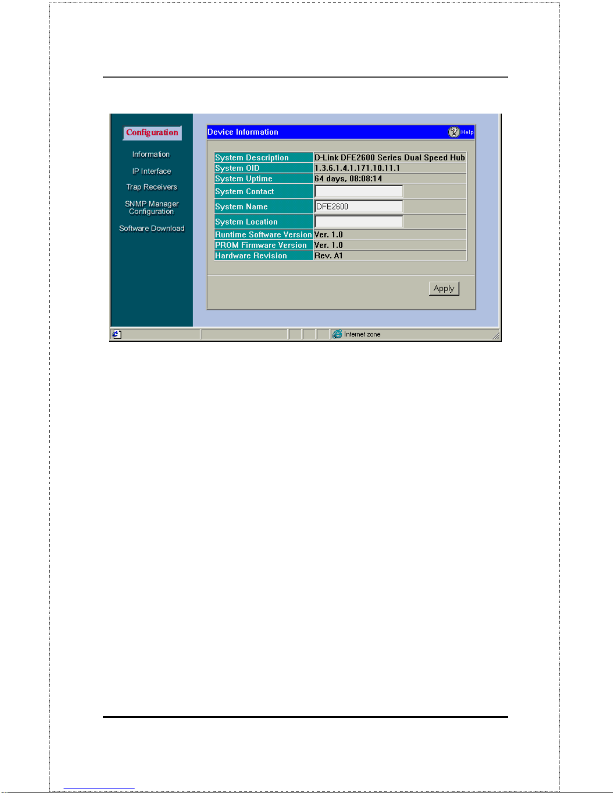
Dual-Speed Stackable Hub Web-based Management User’s Guide
Web-based Network Management74
Items in the Hub Information window are described as follows:
♦ System Description
A description of the hub type.
♦ System OID
The SNMP Object Identifier for this hub type.
♦ System Uptime
The amount of time that the hub stack has been pow-
ered on.
♦ System Contact
Name of the person to contact should there be any
problems / questions with the system.
♦ System Name
A user-assigned na me for the hub.
♦ System Location
A user-assigned description for the physical location
of the hub.
♦ Runtime Software Version
Version number for the resident and
downloadable software.
♦ PROM Firmware Version
Version number for the firmware chip.
This information is needed for new Runtime Software downloads.
Page 87
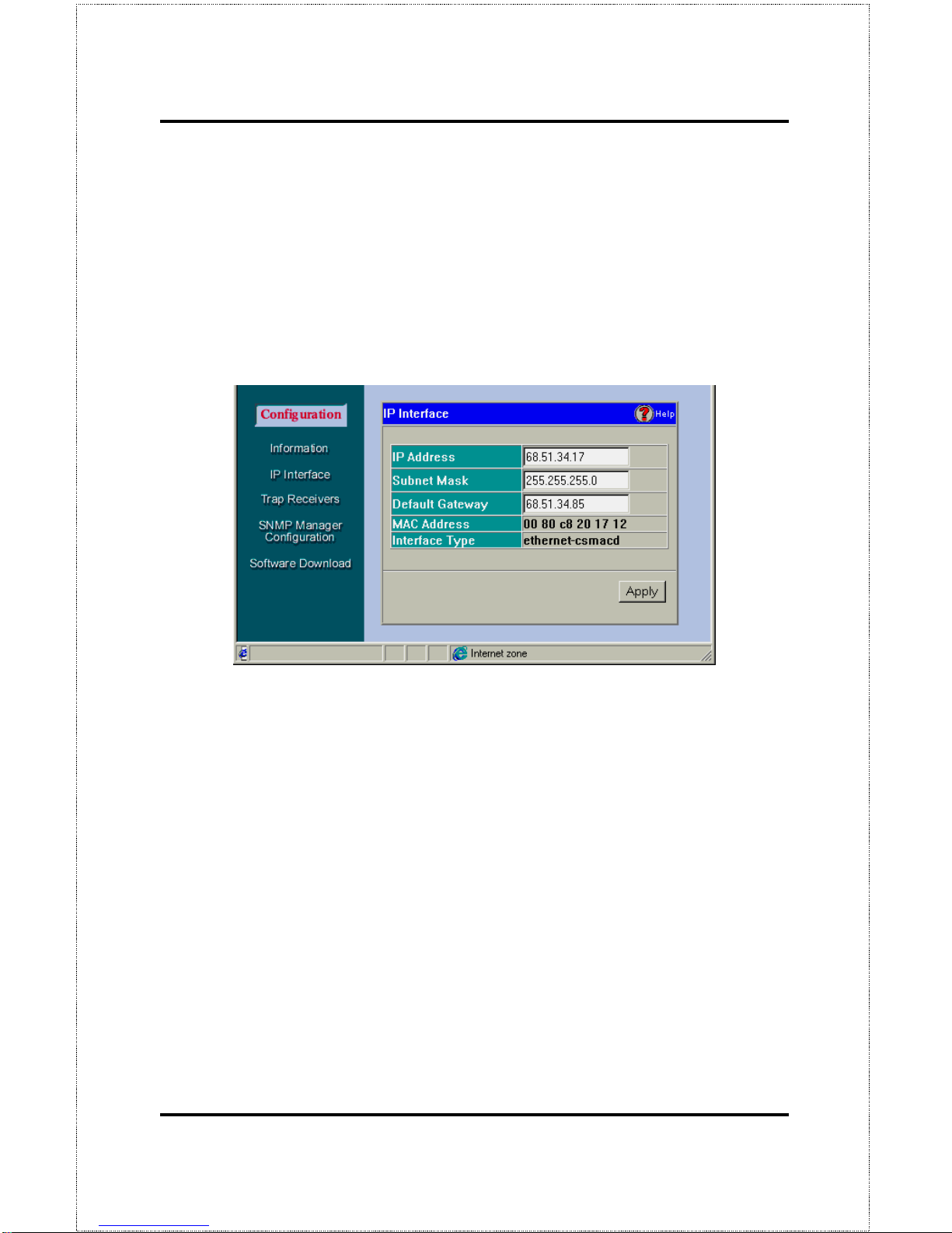
Web-Based Network Management 75
♦ Hardware Revision
Revision number for the hub hardware.
IP Interface
The IP Interface screen displays information about each interface to the device.
The information is described as follows:
♦ IP Address
The Internet address for the device.
♦ Subnet Mask
The subnet mask determines the level of the subnet that
the hub is on.
♦ Default Gateway
The default router for the device.
♦ MAC Address
The ethernet address for the device.
♦ Interface Type
The media protocol.
Page 88
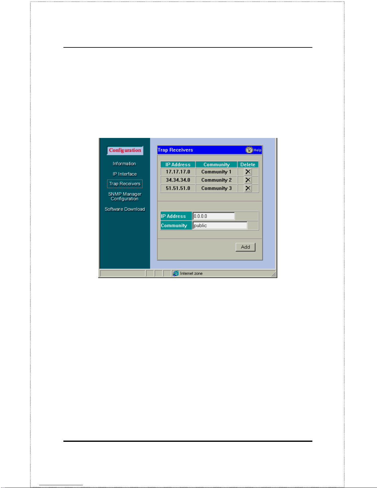
Dual-Speed Stackable Hub Web-based Management User’s Guide
Web-based Network Management76
Trap Receivers
Defining Trap Receivers allows network management stations to be notified
when exceptional events happen.
♦ IP Address
This is the address of the network station that sho uld re-
ceive traps from the hub stack.
♦ Community
This is the SNMP community name to authenticate the
receiving of traps.
♦ Delete
This will remove a trap receiver from the trap receiving table.
To add a Trap Receiver to the list, simply type the IP Address and Community Name in the appropriate boxes and click on the Add button.
SNMP Manager Configuration
The SNMP Manager Configuration screen allows you to define community
strings and access privileges.
Page 89
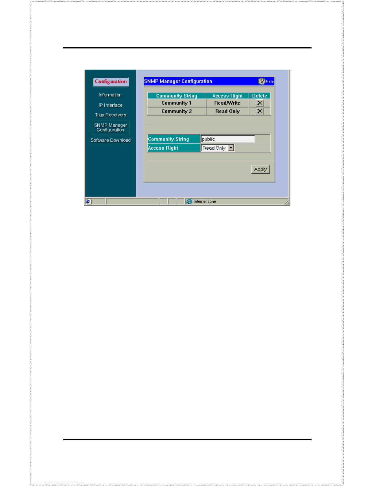
Web-Based Network Management 77
♦ Community String
A user-defined SNMP community name.
♦ Access Right
The permitted access using the SNMP community name.
♦ Delete
Click this to delete the community name.
Software Download
The Software Download screen allows you to cause an immediate update of
the hub parameters and/ or firmware.
Page 90
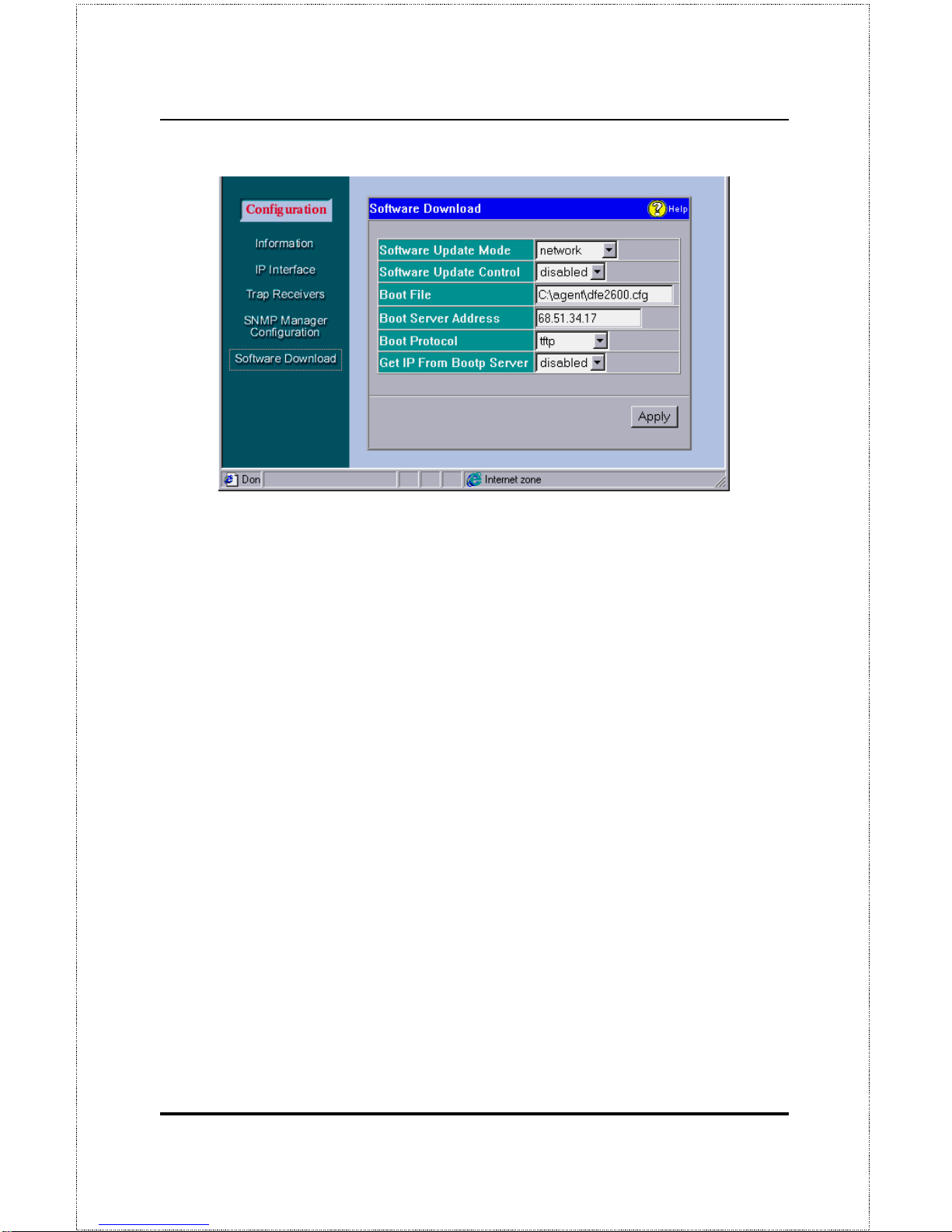
Dual-Speed Stackable Hub Web-based Management User’s Guide
Web-based Network Management78
The fields are described as follows:
♦ Software Update Mo de
Set to either
network
or
out-of-band
. Determines whether the configuration file should be obtained through the
Ethernet network or through the console port.
♦ Software Update Control
Determines whether or not the Hub should
download its configuration file the next time the Hub is booted.
♦ Boot File
The path and configuration file name on the TFTP server. If
you are using bootp-tftp mode, or if
Get IP From BOOTP Server
is en-
abled, the pathname will be obtained from the BOOTP server.
♦ Boot Server Address
The IP address of the TFTP server where the
configuration file is located.
♦ Boot Protocol
Set to either bootp-tftp or tftp
only
. Applies only if the
Software Update Control
is enabled.
♦ Get IP From Bootp Server
If enabled, the IP address will be obtained
from the BOOTP server.
Page 91
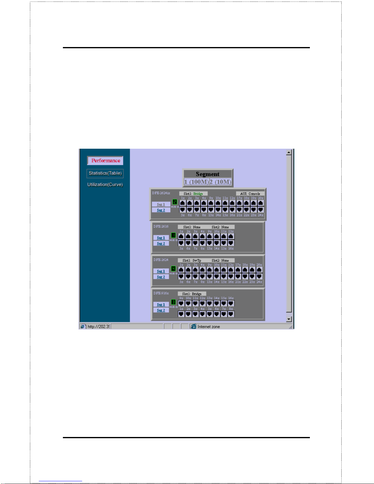
Web-Based Network Management 79
Performance
Hub performance is measured with packet statistics and it utilization in the
network. Clicking on the Performance button and then choosing either the
Statistics or Utilization optio ns on the left causes a representation of your hub
to be shown (see example below). Click on any feature of the representation
to see Statistics or Utilization figures about it.
Statistics
The Hub allows you to collect network statistics on individual ports, 10 Mbps
segments (Seg. 1), 100Mbps segments (Seg. 2) and any Hub in the stack by
clicking on the hub ID number.
Page 92
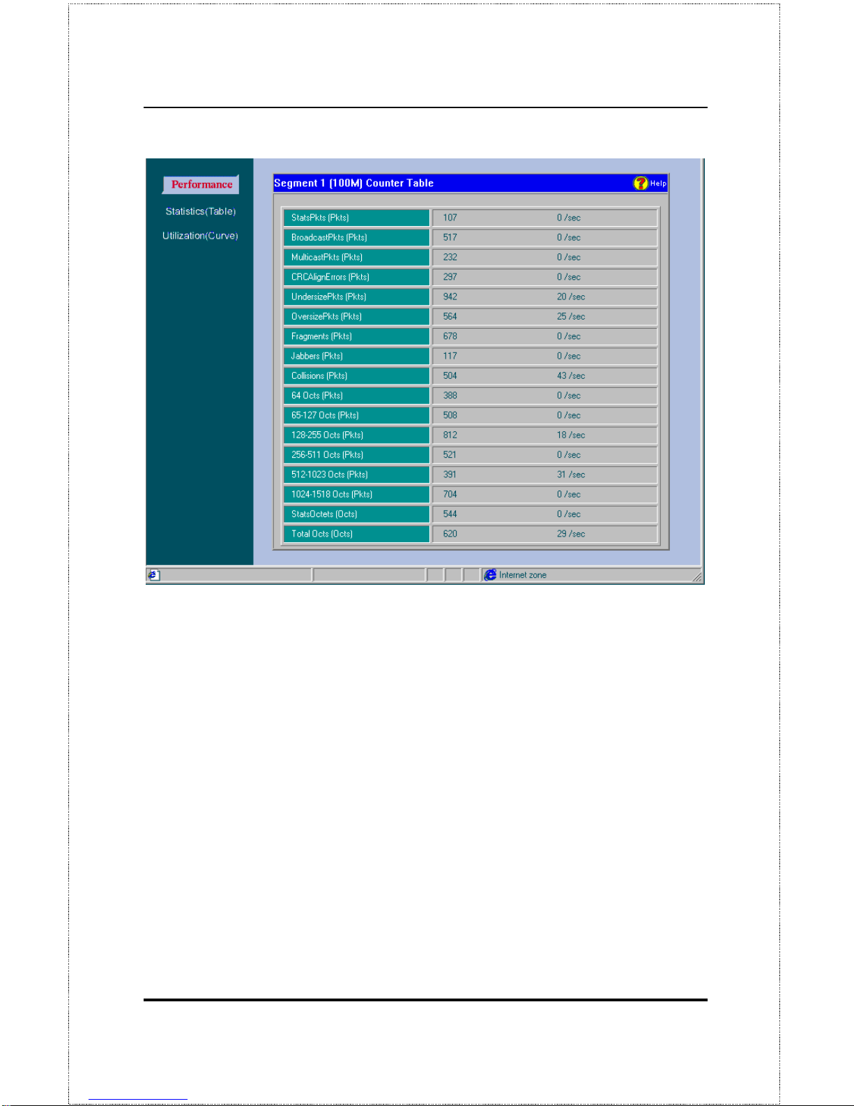
Dual-Speed Stackable Hub Web-based Management User’s Guide
Web-based Network Management80
Statistics collected by the Hub are described as follows:
♦ StatsPkts (Pkts)
Counts valid frames.
♦ BroadcastPkts (Pkts)
Counts valid frames that are broadcast to all
stations on the network.
♦ MulticastPkts (Pkts)
Counts valid frames that are sent to multicast
Ethernet addresses.
♦ CRC AlignErrors (Pkts)
Counts otherwise valid frames that did not
end on a byte (octet) boundary.
♦ UndersizePkts (Pkts)
Counts packets received that were less than 64
octets long (excluding framing bits, b ut including FCS octets) and were
otherwise well formed.
Page 93

Web-Based Network Management 81
♦ OversizePkts (Pkts)
Counts packets received that were longer than
1518 octets (excluding framing bits, but including FCS octets) and were
otherwise well formed.
♦ Fragments (Pkts)
Counts packets received that were less than 64 octets in length (excluding framing bits but including FCS octets) and had
either a bad Frame Check Sequence (FCS) with an integral number of
octets (FCS Error) or a bad FCS with a non-integral number of octets
(Alignment Errors).
♦ Jabbers (Pkts)
Counts frames longer than the maximum 1518 bytes
(octets) with either bad framing or an invalid CRC.
♦ Collisions (Pkts)
Counts transmission collisions on the Ethernet seg-
ment .
♦
The Hub also collects packet distribution statistics categorizing Ethernet
frames by length:
• 64 Octs (Pkts)
• 65-127 Octs (Pkts)
• 128-255 Octs (Pkts)
• 256-511 Octs (Pkts)
• 512-1023 Octs (Pkts)
• 1024-1518 Octs (Pkts)
♦ StatsOctets (Octs)
The number of data octets including those in bad
packets and octets in FCS fields, but does not include preamble or other
framing bits.
♦ TotalOctets (Octs)
The number of octets contained in valid frames.
Page 94
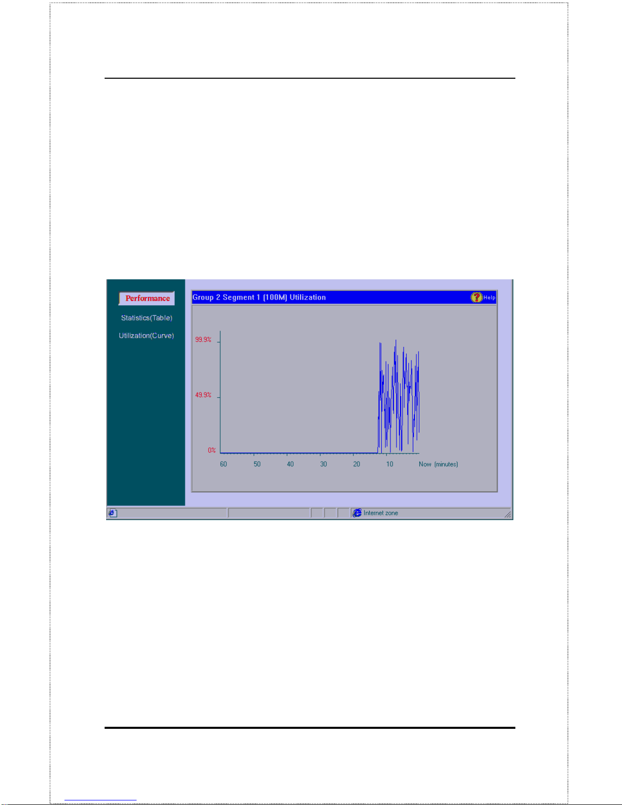
Dual-Speed Stackable Hub Web-based Management User’s Guide
Web-based Network Management82
Utilization
A network segment can be monitored using the Utilization display. Each hub
is divided into two segments; 100Mbps (segment 1) and the 10Mbps (segment 2). When you choose a segment to observe, a graph appears showing
the usage of that segment as a percentage of the total bandwidth (see example
below).
Utilization is calculated and plotted every 10 seconds. A one hour utilization
history can be shown by the graph.
Fault
The operations describ e d in this section allow you to manage the Hub while it
is operating.
Page 95
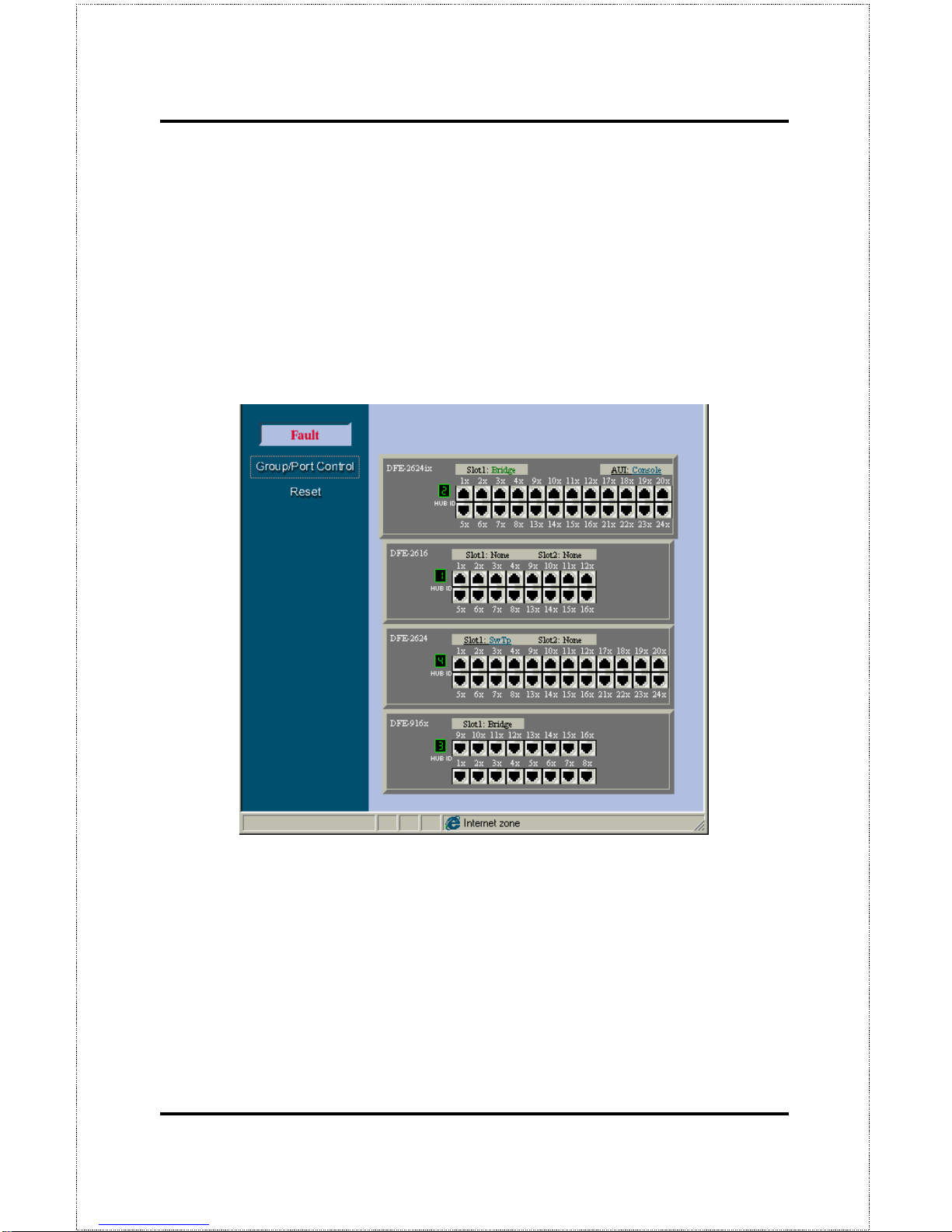
Web-Based Network Management 83
Group/ Port Control
Click on the
Group/Port Control
button on the left side of the screen to show
your hub or stack on the screen. On the stack, simply click on any item you
wish to configure, including an ind ividua l p or t, a hub ( by clicking o n the H ub
ID number), the console and the switch (see the example below).
Port Configuration
Clicking on any twisted-pair port will show the current configuration information of the port.
Page 96
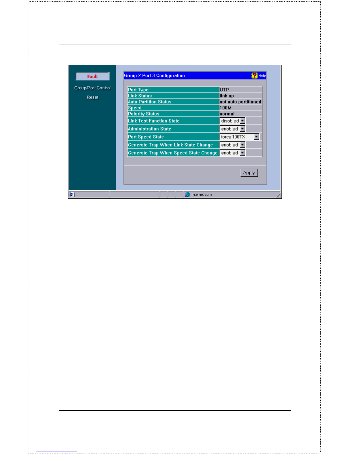
Dual-Speed Stackable Hub Web-based Management User’s Guide
Web-based Network Management84
♦ Port Type
This is a is UTP port which supports both UTP and STP
cabling.
♦ Link Status
Indicates whether the port is online and working (
link up
)
or not (
link down
).
♦ Auto Partition Status
Indicates whether the port has been
auto-partitioned and taken offline or not.
♦ Speed
Indicates the port speed:
100Mbps
or
10Mbps
.
♦ Polarity Status
Indicates the polarity status:
normal
or
reversed
.
♦ Link Test Function State
Indicates whether the port link-test is
en-
abled
or
disabled
. If enabled, the port will check for link pulses, and
will only transmit if there is a good link to another station.
♦ Administration State
Indicates the port partition status, either
en-
abled
or
disabled
.
♦ Port Speed State
Indicates how the port speed is set:
Auto-
Negotiation
(NWay enabled),
10Mbps
, or
100Mbps
.
Page 97
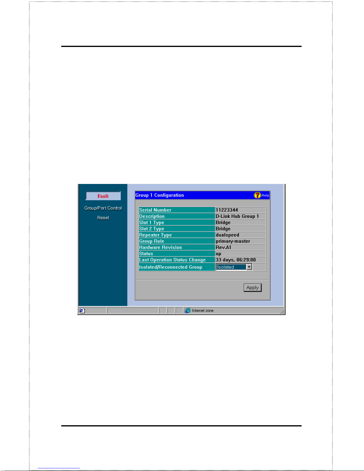
Web-Based Network Management 85
♦ Generate Trap When Link State Change
Indicates whether or not
the port will send a trap if it link status changes.
♦ Generate Trap When Speed State Change
Indicates whether or not
the port will send a trap if it speed changes.
Group (Hub) Configuration
Clicking on a Hub ID number will show the current configuration information for that Hub.
Information displayed on this screen includes:
♦ Serial Number
This is a unique hardware serial number of the Hub.
♦ Description
Information about the hub.
♦ Slot 1/ Slot 2 Type
These indicate the type of module, if present, in
the back-slot of the Hub.
♦ Repeater Type
Detailed information about the Hub.
Page 98

Dual-Speed Stackable Hub Web-based Management User’s Guide
Web-based Network Management86
♦ Group Role
The role of the Hub within the stack, either pri-
mary-master, backup-master, or slave.
♦ Hardware Revision
The version of the repeater hardware board used
in this Hub.
♦ Status
Tells whether the Hub is up (online and working) or
down
.
♦ Last Operation Status Change
Time of the last status change for the
Hub. A status change occurs when the Hub goes online or offline.
♦ Isolated/ Reconnected Group
This is an option to isolate or reconnect
the Hub to the hub stack.
Out-of-Band/ Console Configuration
Clicking on the word
Console
which will appear on the representation of the
hub stack if a console is present, allows the Hub diagnostic port to be configured. The diagnostic po rt can be set to
Console
(in-band) for VT-100
and terminal emulation which may be necessary for basic configurations and
initial setup, or to
out-of-band
management which enables the hub to be
managed using SNMP via the diagnostic port.
Page 99
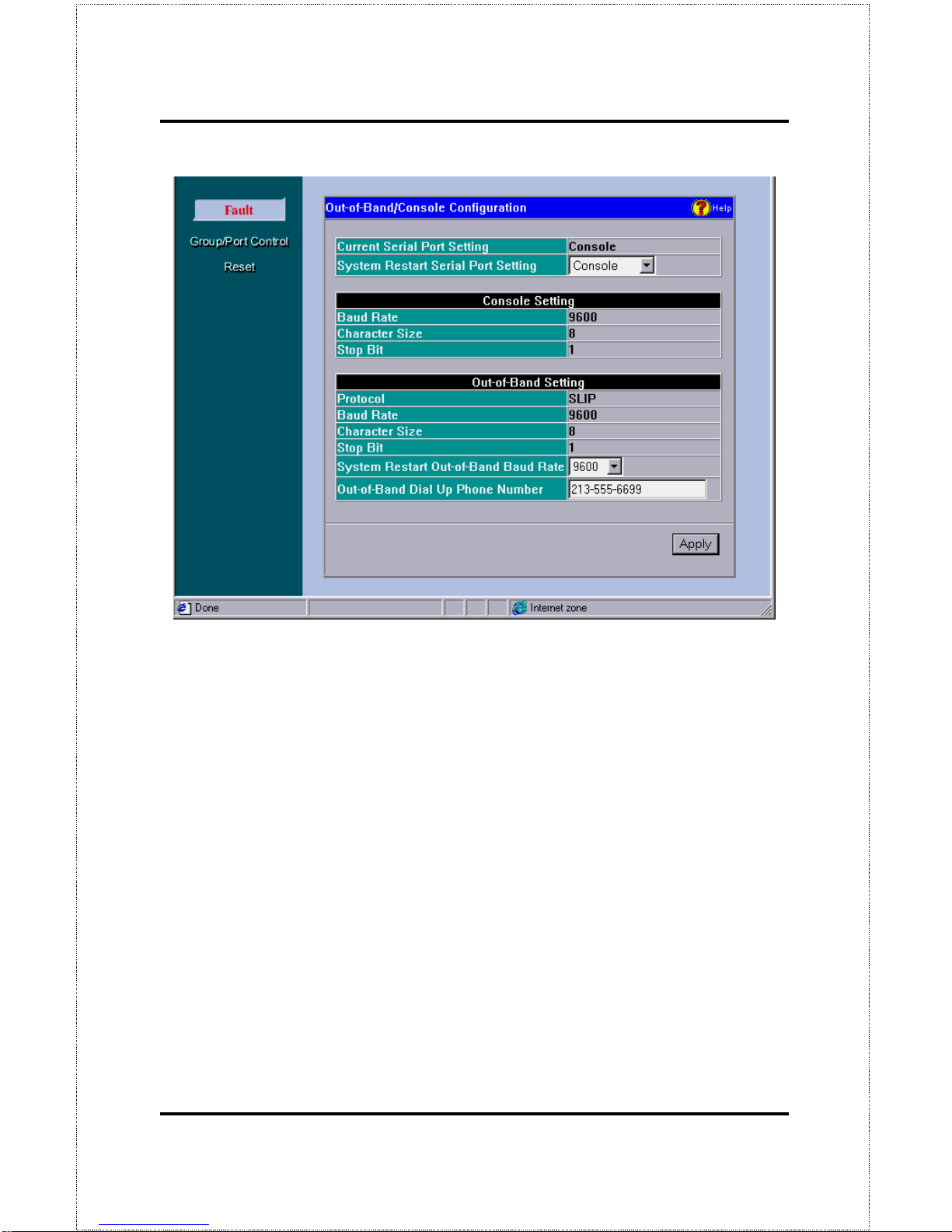
Web-Based Network Management 87
The information is described as follows:
♦ Current Serial Port Setting
Displays the current setting, either
Con-
sole
or
Out-of-band
.
♦ System Restart Serial Port Setting
You can choose to select
Console
or
Out-of-band
management upon reboot.
♦ Baud Rate
Defined in cps (characters per second), it shows the con-
nection speed between the Hub and the console.
♦ Character Size
This is the number of bits in the byte unit of the in-
formation exchange between Hub and console manager.
♦ Stop Bit
This bit marks the end of a unit of transmission (normally a
byte or character).
Page 100
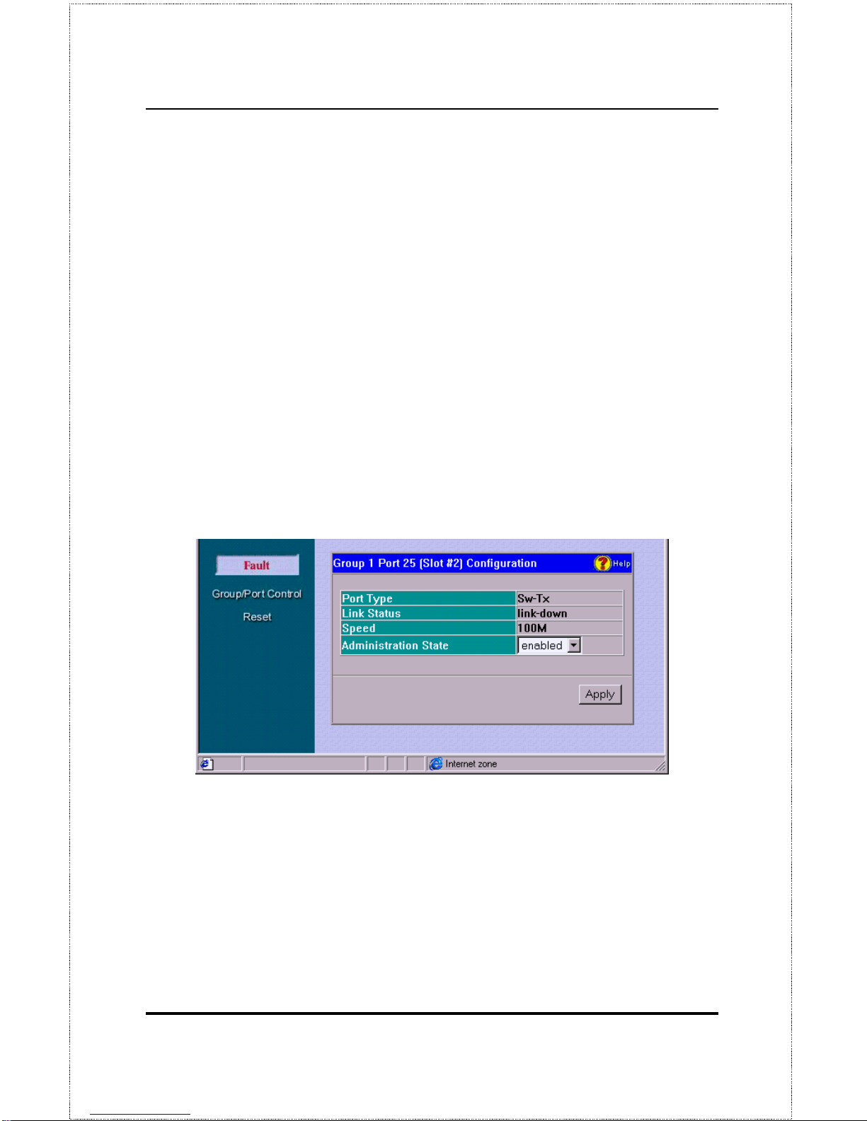
Dual-Speed Stackable Hub Web-based Management User’s Guide
Web-based Network Management88
♦ Protocol
This is the protocol used by the Hub for out-of-band (dial-up)
management.
♦ System Restart Out-of-Band Baud Rate
This sets the baud rate (cps)
on the Hub.
♦ Out-of-Band Dial Up Phone Number
Administrator can place num-
ber here for reference.
Module Port (Slots 1&2) Configuration
When slots 1 or 2 are occupied by either a DFE-260FX Fiber Optic Module
(shown on the graphic representation of the hub as SwFx) or a DFE-260TX
Fast Ethernet Module (SwTp), clicking on the words SwFx or SwTp causes
the following configuration screen to be shown.
Information displayed includes:
♦ Port Type
This item shows either
Sw-Tx
for a Fast Ethernet module
or
Sw-Fiber
for the Fiber Optic module.
♦ Link Status
Indicates link status: online and running (
link up
) or not
(
link down
).
♦ Speed
Indicates the port speed:
100Mbps
or
10Mbps
.
 Loading...