

Page 1
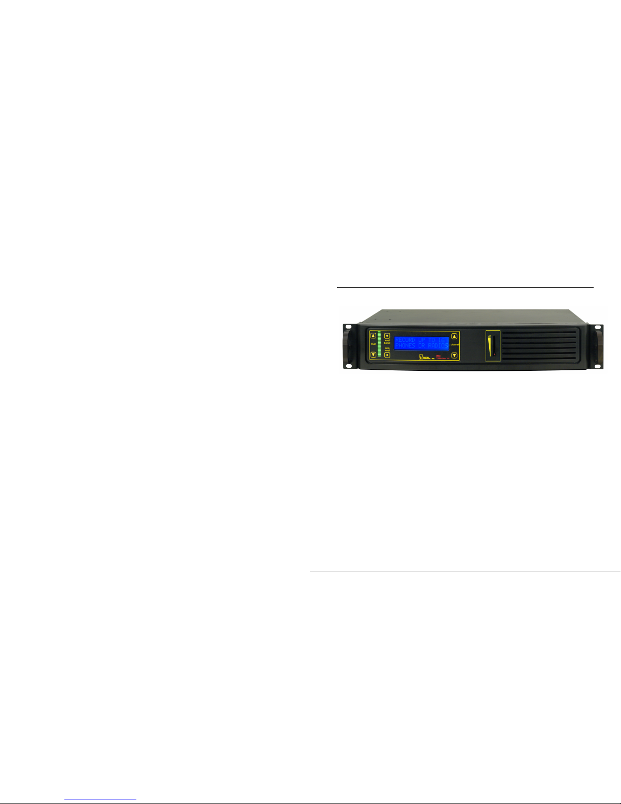
16-Channel Audio Logger
User’s Guide
Page 2

DLI 16 CHANNEL LOGGER
2
Product Features
The logger records up to 16 phones, outside lines, handsets,
microphones or radios simultaneously.
Plug and Play USB simplifies installation.
Recordings can be searched by time, date Caller-ID (CID) or
Touch Tone DTMF signaling.
Flexible recording level settings include: 47dBm fixed gain
adjustment range, 20dBm gain boost, and Auto-Level setting.
Long recordings can be automatically split into easily
manipulated smaller files.
Audio files include signatures with time, date, and recording
details. Utilities are available to embed NG-911 data.
Storage can be controlled on a line-by-line basis to conserve
disk space.
64kbps G.711 recording is supported for commercial and E-911
uses.
Windows utilities help locate recordings, producing call lists and
evidentiary recordings rapidly.
Real-time player utility allows live remote monitoring over
LAN/WAN.
Host PC Requirements
Modern versions of Windows, Server 2008/10/12, W7, 8, 10 or
later are supported. Windows 9x and ME are not supported. XP
and 2003 may work but are not recommended.
A free USB 2.0 480Mbps or USB 3.0 port is required. Slower
11Mbps USB 2.0 ports are not supported.
A separate dedicated local SSD or disk array is highly
recommended for call storage. Many NAS, USB, and remote
shared drives don’t offer the performance required for real-time
audio streaming. Using a dedicated SSD for call recordings
improves streaming performance.
A dedicated Windows PC or server with a minimum of 4GB RAM
is recommended.
Page 3

DLI 16 CHANNEL LOGGER
50
Limited One Year Warranty
The terms of this warranty may be legally binding. If you do not agree to
the terms listed below, return the product immediately in original
unopened condition for a full refund. This product is designed for indoor
use only. Exposure to moisture will void the warranty. The purchaser
assumes the entire risk as to the results and performance of the unit.
No agency, country, or local certifications are included with this unit. It
is the responsibility of the user to obtain such certifications if they are
necessary for the customer’s application. DLI’s entire liability and
exclusive remedy as to defective hardware shall be, at DLI’s option,
either (a) return of the purchase price or (b) replacement or repair of
hardware that does not meet DLI’s quality control standards, when said
hardware has been returned through proper RMA procedure. DLI’s
liability for repair or replacement is to DLI’s customer ONLY. Warranty
service does not include hardware upgrades. No warranty service will
be provided without an original invoice from DLI and an RMA number
provided by tech support. RMAs must be shipped prepaid. RMA
numbers are valid for 15 days. Warranty does not cover products
modified, subjected to rough handling, or used in applications for which
they were not originally intended. Physical damage caused by customer
or in transit to DLI is not covered under warranty. No oral advice or
verbal warranties made by DLI’s employees, dealers, or distributors
shall in any way increase the scope of this warranty. DLI makes no
warranty as to merchantability or fitness for any particular purpose. DLI
assumes no liability for incidental or consequential damages arising
from the use-of or inability-to-use this product. This warranty gives you
specific legal rights. You may have other rights that vary from state to
state. Some states do not allow the exclusion of liability for
consequential damages, so some limitations may not apply.
2695 Walsh Avenue
Santa Clara, CA 95051
Digital-Loggers.com
©1996-2018 Digital Loggers Inc. Rev 3.2.4.0
DLI 16 CHANNEL LOGGER
3
Installation Summary
1. Visit windowsupdate.microsoft.com to ensure you have the
latest USB drivers available from Microsoft.
2. Connect inputs 1-16 via the Amphenol connector. Each line
uses a single twisted pair of wires. Confirm connections and
check wiring.
3. Power-up the logger. Use the buttons on the right to select each
line. Make a test call on each line. Use the speaker to monitor
while adjusting the recording level using the buttons on the left.
The slider controls speaker volume only. Adjust recording levels
using the keypad arrows. Confirm sound quality. Peak levels
should measure below +3dBm. Excessively high input levels
cause distortion.
4. Power up the PC. Insert the CD to install the logging application
as described below. Don’t connect the USB cable quite yet.
5. After the recording application is loaded, attach the USB cable.
Connect directly to a primary 480Mbps USB 2.0 or 3.0 port, not
to a hub. Once attached, the USB configuration on this PC
should not be changed. Windows will load drivers and the
application will need to be restarted if the logger is moved to a
different USB port. Note: A 480Mbps+ port is required. Long
cables and USB extenders are not recommended. 11Mpbs USB
1.1/2.0 ports won’t work.
6. Select a target SSD or disk array to store recordings. Confirm
available disk space. Map a network drive on the workstations
used for playback. Use Windows permissions to limit access to
authorized users.
7. Determine if you’re connected to “wet loops” or dry lines. See
below for more information. Select a separate recording trigger
mode, either VOX or LOOPSTART for each type of line. In VOX
mode, set a trigger level for each line.
8. Install accessory software. Load Call Investigator or Evidence
Builder call cataloging utilities as required on playback
workstations. Install Real Time Player for remote monitoring.
Install Call Detail Recorder to record SMDR, ANI, or ALI from
RS-232 sources.
Page 4
DLI 16 CHANNEL LOGGER
4
Included Hardware
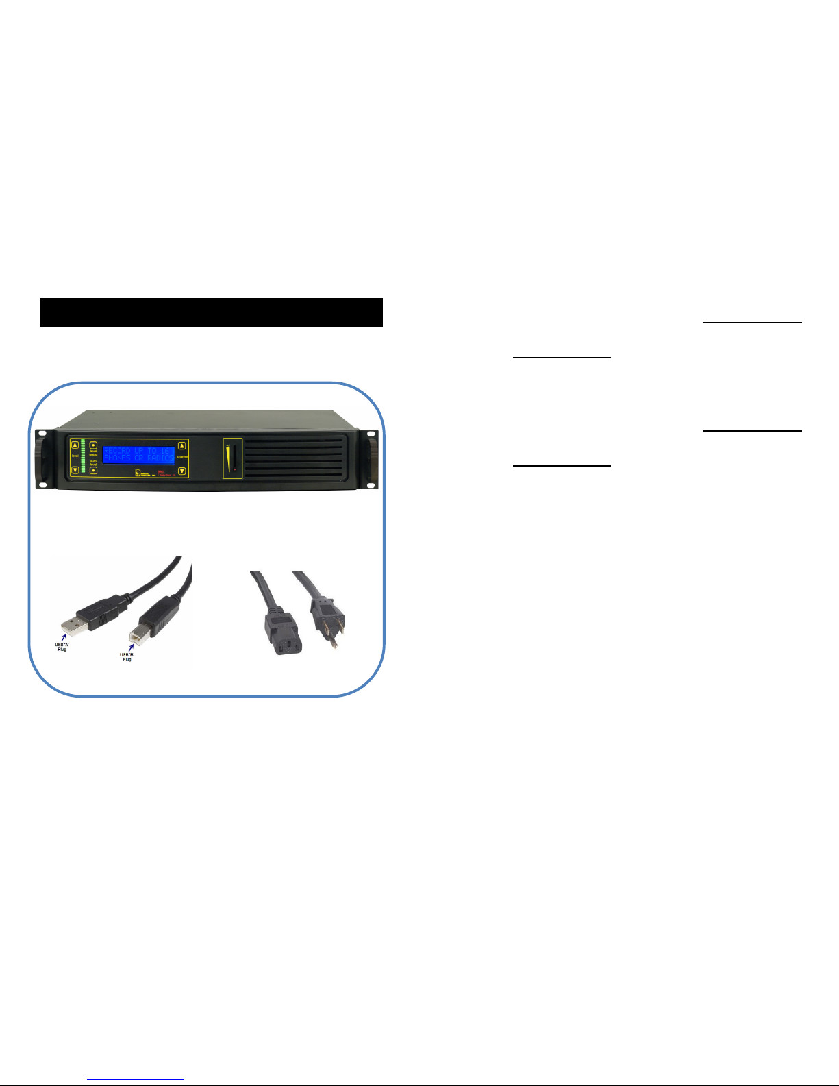
The hardware installation kit includes:
F16W USB Capture Unit
USB “A” to USB “B” cable
IEC Power Cord
DLI 16 CHANNEL LOGGER
49
Speakerphone · 7
Specifications · 46
Storage path · 17
Suggestions · 46
Support · 45
T
T1 / PRI Logger · 45
Test call · 3
Timeout setting · 11
Trim Silence · 24
Twisted pair · 3
U
u-law · 44
Unused lines · 11, 24
Updated manual · 46
USB Data Rate · 46
USB drivers · 3
USB Serial Driver Installation · 25
V
VOX · 3, 24
VOX TIMEOUT · 11
VOX Trigger Level · 20
VOX TRIGGER LEVEL · 11
VU meter · 10
W
Warning Tones · 44
Warranty · 50
Wet loops · 8
Windows Media Player · 44
Windows permissions · 3
Wiring accessories · 5
Page 5
DLI 16 CHANNEL LOGGER
48
F
File names · 44
G
Gain controls · 8
I
Included Hardware · 4
Input Connector Wiring · 38
Input impedance · 46
Installation Summary · 3
ISDN · 7
L
Line Mode · 20
Line Name · 20, 28
Logger Configuration · 23
Logger Event Log · 21
logger service watchdog · 16
Logging Application · 29
LoopStart · 24
LOOPSTART · 3
M
Manual Updates · 46
Maximum Megabytes · 28
Military Loggers · 45
Multiple device support · 15
N
Network drive · 3
Nortel / Avaya ISDN · 7
NO
Outside analog line · 7
P
Package Contents · 2
Power-up · 3
Pre-Record Time · 24
Purge Utility · 22
R
Real Time Player · 33
record automatically · 16
Record Tone Generator · 45
Record Trigger Mode · 27
Recording Consent · 44
Recording File Format · 44
Recording levels · 3
Recording Rate · 46
Related Products · 45
Remote Level Adjustment · 34
REN · 46
RJ-12 Handset Jack · 38, 39
RJ-21 cable · 36
RJ-21 Color Code · 37
RJ-21X Connection · 36
RJ-25 Jack · 39
RJ-31x · 40
RJ-45, RJ-61 and T568 Jack · 41
S
Setting the Record Level · 10
SMDR · 34
Software Setup and Installation · 11
DLI 16 CHANNEL LOGGER
5
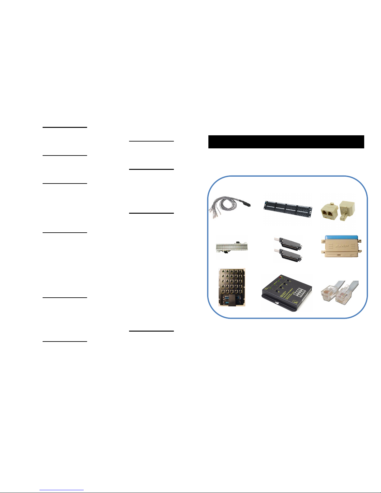
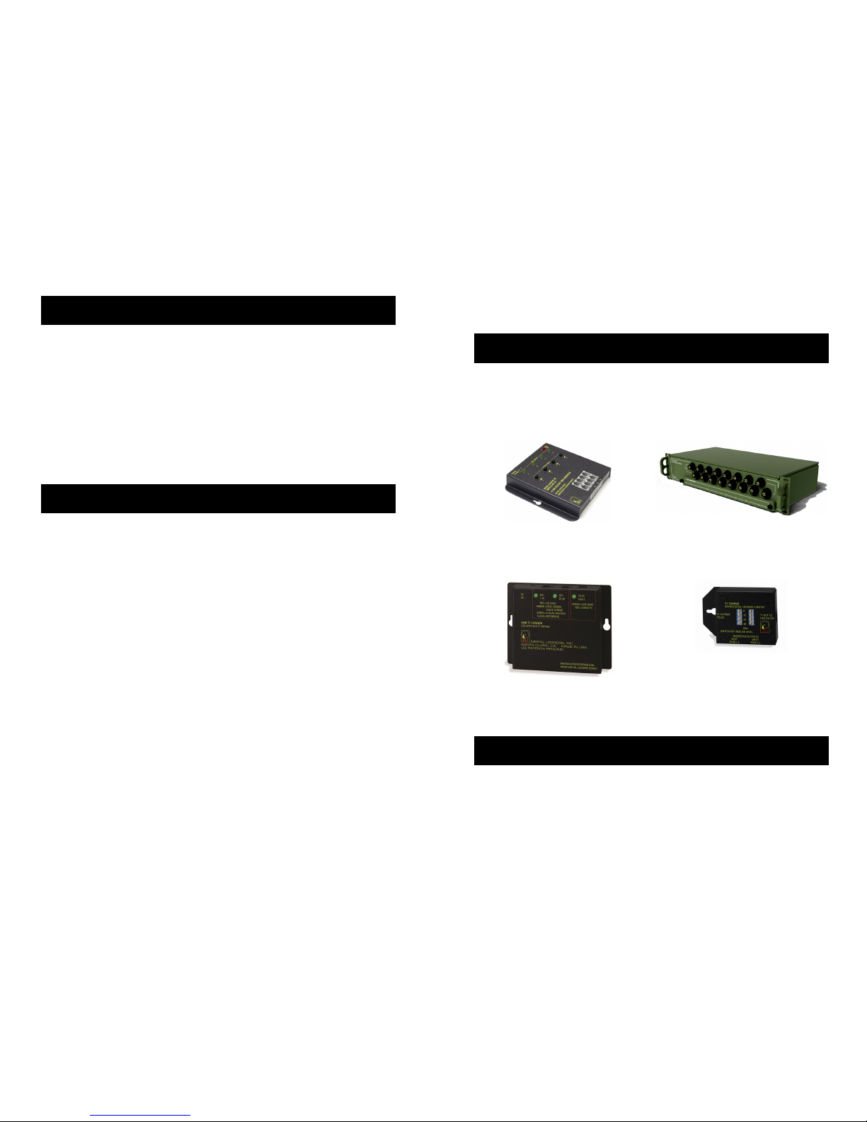
Optional Installation Accessories
Telephone wiring accessories are available from DLI at (408) 330-5599
as well as from telecom distributors such as Graybar.
Octopus Cables
Patch Panels
“Y” Connectors
Punchdown Blocks
AMP Cables
“Goof Plugs”
Breakout Panels
Record Tone
Generator
Handset & Line
Cords
Additional wiring accessories: digital-loggers.com/accessories.pdf
Page 6
DLI 16 CHANNEL LOGGER
6
Power and USB Connections
Verify the input voltage is 90-240VAC. Plug the IEC power cord in to
power up the logger. Use the internal monitoring speaker as an aid to
identifying and connecting inputs, but don’t connect the USB cable until –
after- software installation is completed.
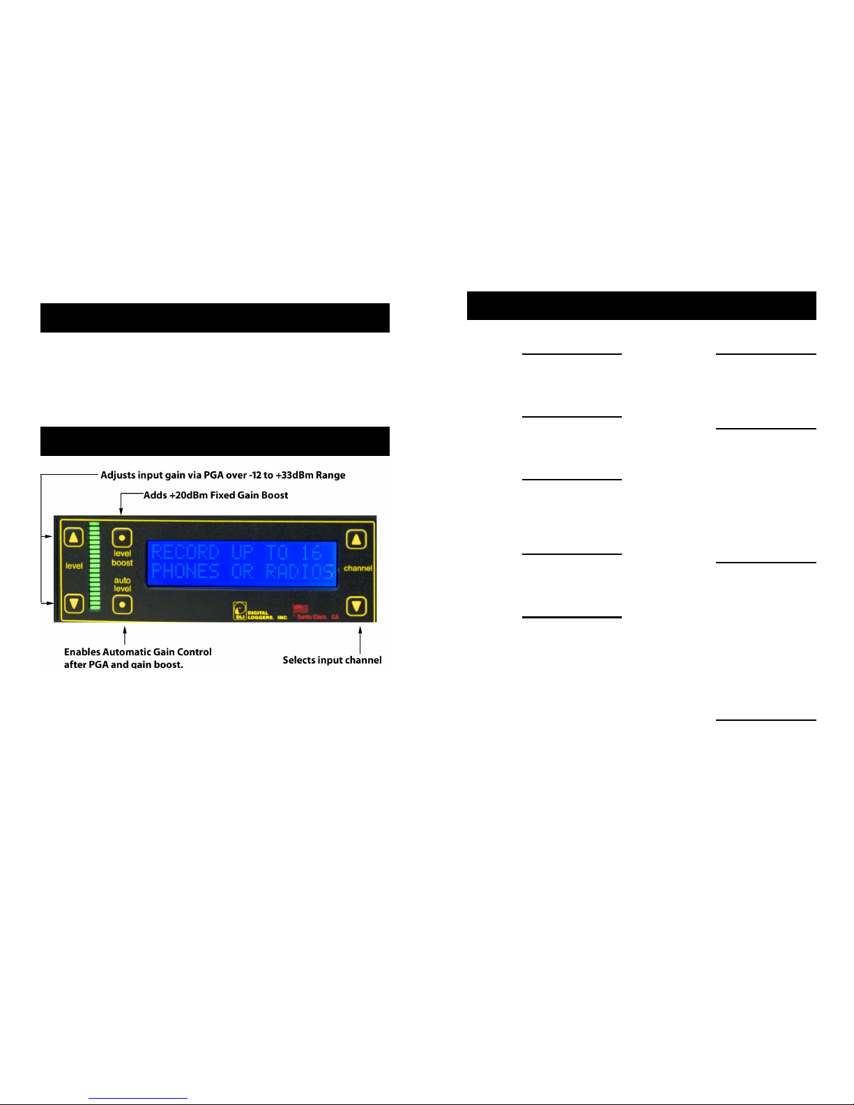
Front Panel Operation
Adjusting recording levels using the front panel is very important.
Recording quality depends on proper level settings. Excessive gain
causes “clipping” distortion. Switching Auto Level on does not preclude
level adjustment because the programmable gain amplifier and level
booster are connected before the ALC. The Level Boost and manual
level settings work in unison. If levels are set too high, distortion will
occur, even with Auto Level enabled.
Level Boost should be enabled only for handsets and microphones with
very low input levels (ie. below -20dBm). To reset all level settings to
defaults, press and hold the up/ down channel buttons simultaneously.
DLI 16 CHANNEL LOGGER
47
Index
1
11Mpbs ports · 3
2
24-hour military time · 44
4
480Mbps USB 2.0 · 3
-48V DC · 8
8
8KBps data rate · 44
A
ALC · 34
Algo · 43
ALI · 34
AMP · 37
Amphenol cable · 37
Amphenol connector · 3
Analog accessory jack · 7
analog extension · 7
analog port · 7
ANI · 34
Audio files · 44
Auto Level · 35
Automatic Level Control · 34
AUX jack Connection · 39
B
Balanced vs. Unbalanced Lines · 42
bar graph · 19
C
Call Investigator · 31
Caller-ID · 10
CHAMP · 37
Channel Configuration Settings · 27
Color Codes · 36
Complex mode · 24
Continuous · 24
D
D/A converters · 43
D/A Converters · 43
DC signaling · 8
Digital station set · 43
Directories · 44
Disk space · 3
Distortion · 3
Dry lines · 8
DTMF Settings · 24
E
Elapsed recording time · 44
Evidence Builder · 32
Explore Calls · 30
Page 7
DLI 16 CHANNEL LOGGER
46
loggers.com. We'll be glad to help. Suggestions for product
improvements including manual corrections are welcome:
[email protected]
Manual Updates
Download an updated manual:
Digital-Loggers.com/F16WMan.pdf
Specifications
Enclosure material CRS steel powder coated
Frequency Response 300-3400Hz +/- 2dB
Input impedance >10K ohms DC Blocked, fully balanced
Input isolation 2000V min 30s test to ground
Line surge suppressors 600W SIDAC
LCD 2x16 Backlit with powersave
Operating temperature -20º to 120ºF, -28º to 49ºC
Power cord C13 18AWG stranded, UL SJT FX3CVW1
Power requirement 90-240VAC 50-400Hz autosense 8W nom.
Weight Bare unit 11.2 lbs, Ship wt. 12.4 lbs
Recording Rate u-Law G.711 64kbps, 8kBps
REN 0.1
Size 19” RETMA rack. 17” width with ears
removed. 1-U 3.50” height, 6.25” depth
USB Data Rate 480Mbps required
DLI 16 CHANNEL LOGGER
7
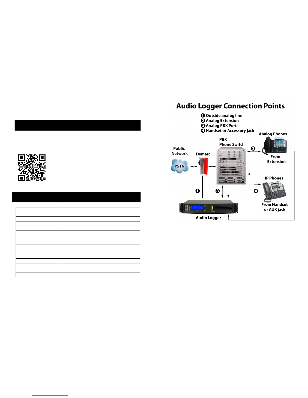
You can record from…
1. an outside analog line.
2. an analog port on a PBX (such as a voicemail port).
3. an analog extension or speakerphone.
4. any handset, headset, or analog accessory jack
5. microphones or other analog audio sources
To record VoIP phones, tap an outside analog line, handset, or analog
accessory jack on the back of the phone. ISDN and Ethernet are not
analog audio signals. To record proprietary formats like Nortel ISDN
extensions, you can use D/A converter designed specifically for your
PBX. DLI carries T1/PRI loggers for direct digital recording of outside
lines. PRI loggers are often used in VoIP systems with PRI connections.
Page 8
DLI 16 CHANNEL LOGGER
8
Wet Loops vs. Dry Lines
A voltmeter is helpful in determining if your inputs are “wet loops” or dry
lines. Wet loops typically carry -48V DC when measured off-hook. Wet
loops are used to connect to your telecom provider, to your PBX, or to
analog phone extensions. Dry lines such as headsets, radios,
microphones and speakers carry audio, but no DC signaling voltage.
After you’ve determined a line type (either wet-loop or dry line), select a
recording trigger: either Loop Start or VOX. Outside wet loops and
inside analog extensions normally use Loop Start signaling. All dry lines
use VOX signaling to trigger recording.
VOX Recording for Dry Lines
To bridge a dry line using Voice Operated Switch (VOX):
Note: VOX mode is used for dry lines (lines that do not carry
signaling voltage). Examples are handset connections,
headsets, radios, microphones and speakers.
Use a punch-down block, handset Y connector, breakout box, or
RJ-11 octopus cable to connect each line (two twisted wires) to
the logger. Each of the logger inputs connects in “bridge”
fashion across the existing wiring.
Verify that the line audio level is within telecom specifications.
Peak level should not exceed +3dBm. Gain controls should be
set so that recording levels do not exceed 0dBm. Use Level
Boost only if the input level is below -20dBm. If the VU meter
peaks, the line level is too high. Reduce it using the manual gain
controls, turn off Level Boost, and/or switch Auto Level on.
Use Level Boost for handsets, microphones, and low-level
signals only.
Rename the line label by clicking on the line name. Type the
new name and press Enter. For example, a handset tap or
analog extension connected to LINE 01 might be renamed
“Support Desk.”
Set the line configuration mode to VOX by clicking on the line
mode.
DLI 16 CHANNEL LOGGER
45
Recording header files also contain human-readable .XML tags with call
information. These fields may be used to create third-party applications.
Related Products
DLI manufactures these related products:
Record Tone Generator Single and Multi-Channel
Military Loggers
T1 / PRI Logger
T1 and DS3 Taps
Learn more: digital-loggers.com
Support
Please visit digital-loggers.com for more frequently asked questions, free
driver updates, manuals and accessories. If we haven't answered your
questions here, please call (408) 330-5599 or email support@digital-
Page 9

DLI 16 CHANNEL LOGGER
44
there are hundreds of D/A converters available. Be sure to purchase
one that matches your station sets. DLI carries some Algo products.
Recording Consent and Warning Tones
Many states require the consent of two parties prior to recording. In
locations where there is “no reasonable expectation of privacy”, such as
911 PSAPs and prisons, consent is not normally required. Most PBXs
can be easily set up to provide a warning such as, “Your call may be
monitored and recorded for quality assurance...” DLI manufactures
optional record tone generators which inject a periodic warning tone on
outside analog POTS lines or extensions. DLI can’t offer legal advice or
information on admissibility of recordings, so check with your attorney to
confirm compliance with state and local laws prior to recording.
Recording File Format
Audio files are recorded using the industry standard -law (pronounced
“mew-law”) format. Files are grouped in directories, with each channel
and date corresponding to a single directory. The line name
corresponds to the recording directory name, and can be changed. File
names are sorted by start time in ascending order. All time values are
standard 24-hour military time. A separate subdirectory is created for
each day. The following example shows how the time and date stamps
are directly coded into the file names:
Channel Day File Name
Directory Subdirectory
LINE01 20130403 212450da.au
Path: Recording_Directory/LINE01/20130403/212450da.au
In this example, a call arriving on line one, on April 3rd, 2013 was
recorded, starting at 21 hours, 24 minutes, and 50 seconds (9:24:50PM).
-law files are recorded at a 64kbps=8KBps data rate, so there is no
audio quality loss due to compression. The length of each file is directly
proportional to the length of the call. Windows Media Player displays
the exact elapsed recording time.
DLI 16 CHANNEL LOGGER
9
Set the VOX trigger threshold to a level slightly above the noise
floor (background noise level) of each line.
Loop Start Recording for Wet Loops
To bridge a wet loop line using Loop Start (LPS):
Note: Loop Start mode is used only for “wet loop” analog lines,
such as analog extensions and outside POTS lines. Measure
the idle DC voltage on the line to confirm that 48VDC is present
on a wet loop.
Verify that audio input levels are within standard telecom
specifications. Peak level should not exceed +3dBm. Gain
controls should be set so that recording levels do not exceed
0dBm. Disable Level Boost for wet loops.
Using a punch-down block, breakout box, or octopus cable to
connect each outside line to the logger. Each line is a two wire
pair. Each of the logger inputs connects in “bridge” fashion
across the existing wiring.
Verify audio quality using the speaker on the logger. If the audio
sounds distorted, the recording level may be set too high. Turn it
down or select Auto Level.
Rename the line label by clicking on the line name. Type the
new name and press Enter. For example, an outside wet line
connected to “LINE 01” might be renamed “(408) 330-5599”.
Set the line mode to LPS by clicking on the line mode.
Connecting Radios
Manufacturers use a wide variety of radio connectors, so you’ll first need
to locate a mating connector. After that, it’s a simple two-wire connection
from the receiver to the logger. You can directly bridge across the
speaker, headset, or ear bud at levels up to +3dBm. Levels higher than
that will cause clipping distortion. If you are bridging a loudspeaker, turn
the level down or add a series resistor to attenuate the signal. Connect
to a pair of input pins on the logger. A punch down block is usually the
most convenient way to mix radio and phone lines.
Page 10
DLI 16 CHANNEL LOGGER
10
If you’re connecting a radio transceiver, and you’d like to record both the
transmitted and received audio in the same recording file, you’ll need a
4-wire to 2-wire converter. DLI builds custom military intercom and radio
loggers as well as specialized recorders for military and E-911/P25
applications.
Setting the Record Level
Recording levels can be controlled from the front panel using a
membrane keypad: Use the up/down arrows to select a channel, then
use the arrows on the left side to the logger to adjust the recording level.
The slider-bar and speaker help verify audio quality.
It’s important to set the recording level correctly. Low levels are hard to
hear. High levels cause distortion in the recordings, making it difficult or
impossible to decode Caller-ID or DTMF. This distortion is known as
“clipping”. Set each line so the VU meter never quite reaches the red
peak bars during normal recording. If you’re unsure, start by setting the
gain to 0dBm, turn Level Boost off and select Auto Level.
To reset all level settings to defaults, press and hold both the up and
down channel selection buttons simultaneously.
Setting VOX Trigger Level and Timeout
To use VOX mode, first adjust the recording level to avoid clipping as
described above. Once the recording level is set correctly, hang up the
line and adjust the VOX trigger level about 6dB above the noise floor.
The VOX trigger level is the threshold at which recording will begin. In
other words, when the logger “hears” a sound louder than the VOX
trigger level, it will start to record. On a line with background noise, you’ll
need a higher trigger level.
Recording will continue until silence is detected for a period of time. This
period of time is called the VOX timeout. Start with a timeout of 30
seconds for phone calls, and 10 seconds for radios. Listen to the
DLI 16 CHANNEL LOGGER
43
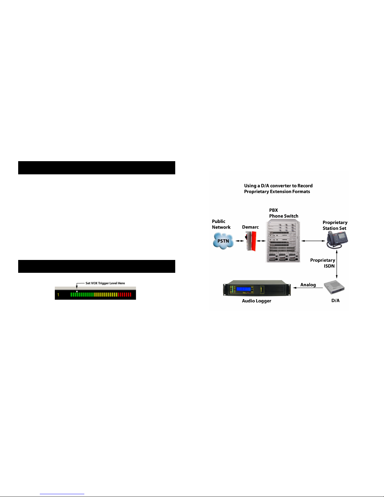
D/A Converters
D/A stands for Digital-to-Analog. D/A converters or “DACs” install
between digital lines (usually station sets) and an audio logger. D/A
converters work by converting the signal stream from a digital station set
into the standard analog format used in an audio logger. They are
available in single and multi-channel versions.
Since there is no "standard" for proprietary digital station set
interconnects and line formats, D/A converters are best purchased from
the manufacturer of the PBX. PBX manufacturers often call these
“recording adapters”.
Multi-channel D/A converters are available as stand-alone units or PCI
cards. These cards are sold by Dialogic (now Intel), Algo, and others.
Every proprietary phone switch uses a unique non-standard format, so
Page 11
DLI 16 CHANNEL LOGGER
42
Jack
Position
s
Line USOC
RJ61
T568A
T568B
(AT&T) 100BT
(LAN)
1 Line 4 Ring wht/brn wht/grn wht/org wht/blue
2 Line 3 Ring wht/grn grn/wht org/wht blue/wht
3 Line 2 Tip wht/org wht/org wht/grn wht/org
4 Line 1 Ring blue/wht blue/wht blue/wht
5 Line 1 Tip wht/blue wht/blue wht/blue
6 Line 2 Ring Org/wht org/wht grn/wht org/wht
7 Line 3 Tip Grn/wht wht/brn wht/brn
8 Line 4 tip Brn/wht brn/wht brn/wht
Balanced vs. Unbalanced Lines
Balanced lines are lines use to cancel
noise. In balanced phone lines, two
wires are twisted together so that each
wire picks up the same amount of noise.
At the receiving end, the noise is
subtracted, and the resulting output is
the sent audio, minus the noise. A
balanced line becomes "unbalanced"
when unintentional leakage to ground
occurs. Unbalancing a phone line
causes noise. This can be a result of
poor insulation somewhere along the
line, or a bad connection. The problem is often worse in the winter,
when outside lines are wet and leakage to ground occurs along the line.
Audio is transmitted down relatively short unbalanced lines using coaxial
shielding. This shielding prevents electromagnetic noise from affecting a
single wire. The inputs to all DLI loggers are balanced lines. These
inputs may be connected directly to unbalanced (ie. Coaxial) lines, and
the ground may be connected to either side of the logger input. In other
words, either of the logger input lines (known as Ring and Tip) can be
grounded.
DLI 16 CHANNEL LOGGER
11
recordings, and then adjust the timeout value to your liking. An
excessively long timeout setting will combine multiple calls into a single
file. An excessively short setting will cause calls to break apart into
multiple recording files during periods of silence.
The VOX trigger level is adjusted by sliding the white arrowhead above
the VU meter bar graph.
VOX trigger level settings do not apply to lines operating in the
LOOPSTART, Continuous, or Complex modes.
When operating the logger in VOX mode, two settings are vital: VOX
TIMEOUT and VOX TRIGGER LEVEL. Set the VOX trigger level slightly
above the noise floor (ambient noise) on the line when the phone is onhook. If you change the recording level using the keypad on the front of
the logger, you may need to readjust the VOX trigger level in the app.
Unused Lines
Logger inputs are sensitive. Unused lines may record noise coupled
from adjacent wiring, or produce feedback or hum in the speaker when
Level Boost is enabled. Set unused lines OFF in the application, turn the
gain down on unused lines, or terminate the wiring. A ground lug is
provided on the rear panel of the logger. You may wire this to a good
ground connection to prevent noise from entering via the power cord.
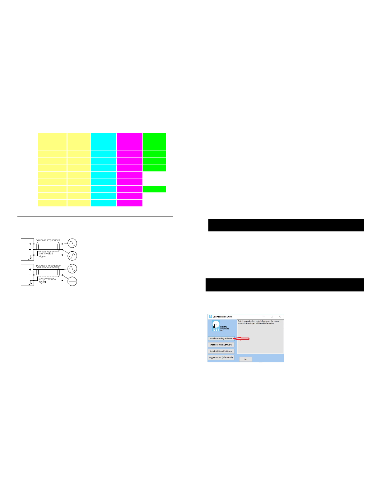
Software Setup and Installation
Inserting the driver CD and allowing setup.exe permission will spawn an
installer shell. Start by installing recording software on the machine that
will be attached to the USB cable.
Page 12
DLI 16 CHANNEL LOGGER
12
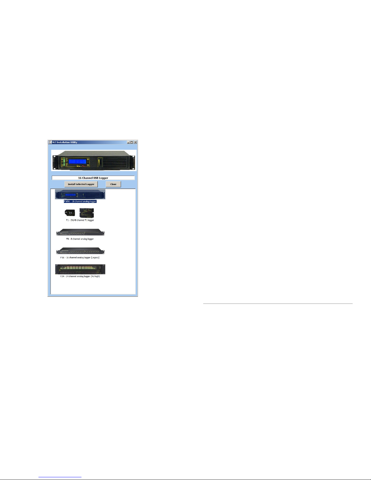
Click on the photo of the logger and click Install Selected… to begin
installation. The USB cable should still be disconnected at this point.
If you haven’t updated Windows recently, we recommend a visit to
windowsupdate.microsoft.com to obtain the latest USB host drivers
before installing the logging software. If you’re running automatic
updates, you should be OK. After updating, insert the logger installation
CD into your CD-ROM drive. For a smooth installation, don’t connect the
logger USB cable until you have completed installing the software
drivers.
Initial setup starts after you grant permission:
DLI 16 CHANNEL LOGGER
41
security and fire alarm systems that provide exchange to alarm reporting
devices.
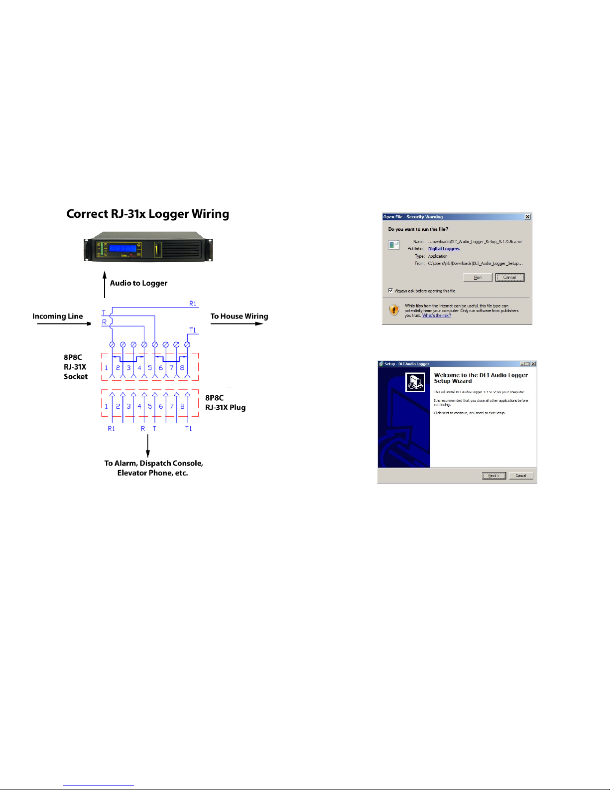
In an RJ-31x installation, the phone line is wired in series through the RJ31X; from there, tip and ring pass through the dialer. A normally closed
relay opens if the alarm is activated, seizing the circuit for alarm use,
while temporarily disconnecting lower priority equipment (such as a
house phone) to prevent disruption of the dialing sequence.
The most common RJ-31x installation is an 8-position, non-keyed
miniature jack with shorting bars across terminals 1-4 and 5-8. Inserting
the modular plug lifts the contact wires away from the shorting bars,
extending the tip and ring circuit to the series leads going into the alarm
device. The audio logger connects to pins 4 and 5 of the jack in a
"bridging" configuration. When the plug is removed from the jack, metal
tabs inside the RJ-31X provide direct connection of tip and ring back to
the other locations, bypassing the alarm device. This design lets the
dialer control the line for exclusive use when in alarm mode. It also helps
isolate defective or improperly wired equipment by disconnecting the RJ31x plug to route tip and ring directly to lower priority equipment. In
some 911 installations, a dispatch console will be rerouted to a backup
console by connecting the backup console to the "house phone"
connections on pins 1 and 8. Always connect the logger to the
OUTSIDE (Socket Side) of the FIRST jack socket, pins 4 & 5.
Some technicians may install a "shortcut" or de-populated four-terminal
version of the dialer jack. In the shortcut dialer jack, the jumpered
terminals (which supervise the presence of the plug) are missing. This
"shortcut" jack can't detect the presence of the modular plug. It is best
to install a fully populated RJ-31X jack, and properly connect all
terminals. All RJ-31 X jacks should be installed in front of any other jacks
in the system so that when an alarm occurs, automatic dialing will take
priority and seize the line, leaving all other phones disconnected.
RJ-45, RJ-61 and T568 Jack Connection
Although it's not technically correct, the term "RJ-45" is now used to refer
to any standard 8 pin jack in telephony or networking applications.
Although originally designed for analog audio, RJ-45 jacks are now most
commonly used in Ethernet applications. Eight pin jacks can carry four
analog circuits. An Ethernet jack can’t be connected to an analog input.
Listed below are the correct color codes for 8-pin telecom and Ethernet
jacks.
Page 13
DLI 16 CHANNEL LOGGER
40
Alarm and security companies use a special type of jack, called an RJ31x. It is an "exclusion type" dialer jack. It is typically a Leviton style 8
pin jack with an internal switch. Similar wiring may be done on KT-66 or
W110 punch down blocks with bridging clips. Each 66 block handles 3
lines of RJ-31x wiring configuration, and all the pin order matches the
order of the RJ-31x jack pins. The first jack connects to pins 1-8, the
second to pins 9-16, and the third to pins 17-24. This type of wiring is
commonly encountered in commercial alarm installations, fire alarms,
elevators, and 911 dispatch consoles. RJ-31X jacks are required for
DLI 16 CHANNEL LOGGER
13
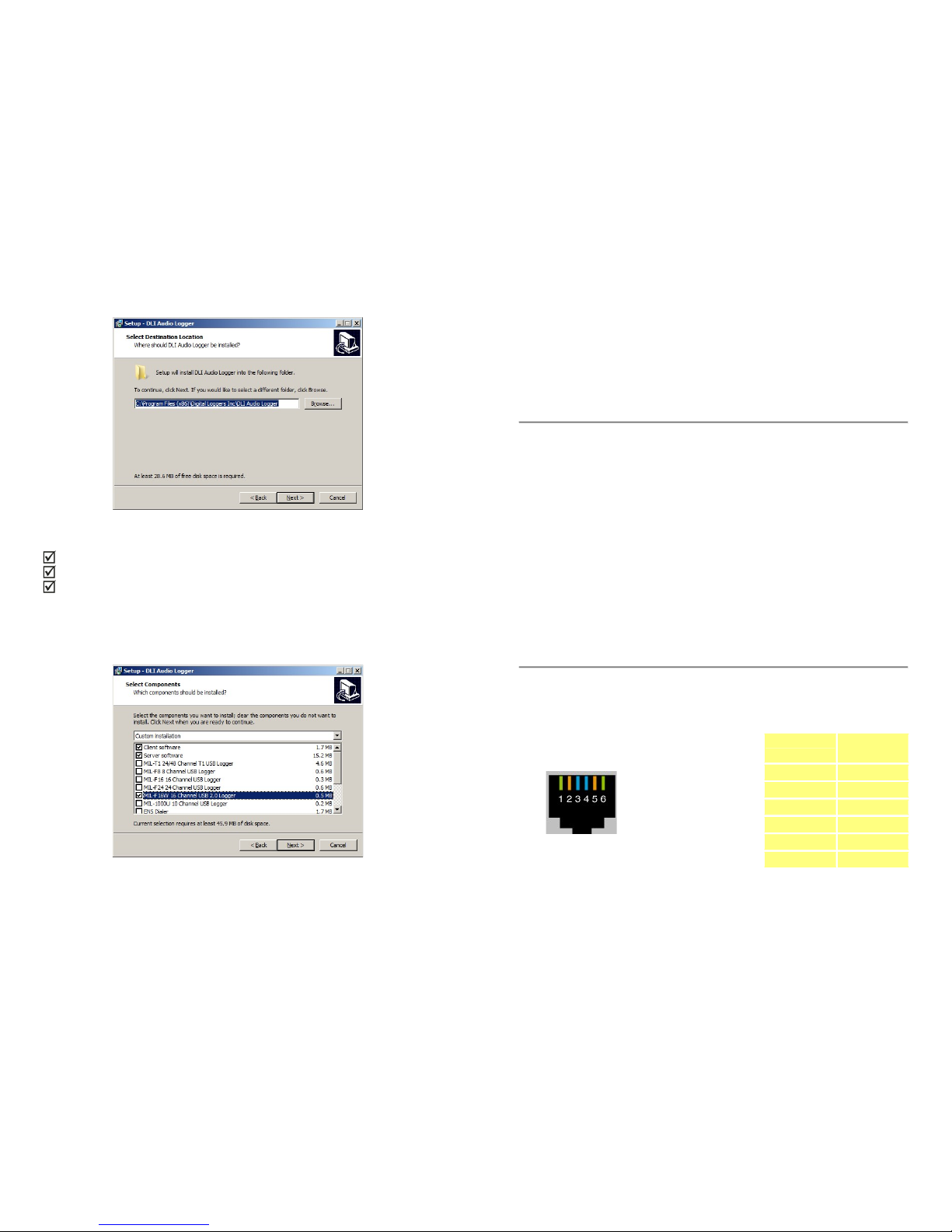
Select RUN, Continue, then select an installation directory and shortcut
name.
Select an installation destination:
Page 14
DLI 16 CHANNEL LOGGER
14
Next, ensure that:
Client Software
Server Software
MIL-16W 16 Channel USB 2.0 Logger
are checked. NB: The MIL-16 USB Logger uses different drivers which
are not compatible with this product. Make sure you have selected
F16W as shown:
Later, after the server software is installed, client software can also be
installed on an unlimited number of workstations connected to your
DLI 16 CHANNEL LOGGER
39
To connect an RJ-21X to an RJ-11 jack, you can use either a rack mount
patch panel with 24 RJ-11 jacks, or a "harmonica" or "octopus". An
Octopus cord has a single 50 pin AMP connector (RJ-21X type) on one
end, and 24 RJ-11 type plugs on the other end. Another useful
connector is an RJ-21 “Tap” or “Y” cable. These optional parts and
cables are available directly from DLI and through telecom dealers.
RJ-12 Handset Jack and AUX jack Connection
A handset jack is a small 4 pin connector which carries the speaker and
microphone signals between a telephone and handset. Many phones
including most Cisco VoIP phones have an AUX connector which
provides analog audio output to a headset or logger. This is a good place
to bridge an audio logger, since both incoming calls and intercom
conversations for a single extension may be recorded at this point. The
default VOX and ALC settings will work fine with the typical handset level
with the Gain Boost setting enabled. To record from a handset,
“backhaul” the audio to the logger via either a “Y” connector, and AUX
jack, or make the connection within the phone itself. This can be done
with an unused pair on an existing cable. Smaller handset jacks won’t
make a reliable connection in larger RJ-11 jacks. Y connectors for the
smaller handset RJ-12 plugs, and cables with RJ-11 to RJ-12 jacks are
available from DLI.
RJ-25 Jack Connection
An RJ-25 jack is a standard 6 pin, 3 pair telephone jack. Each colored
pair carries one analog signal.
Jack
Positions
Line USOC
RJ25
1 Line 3 Tip wht/grn
2 Line 2 Tip wht/org
3 Line 1 Ring blue/wht
4 Line 1 Tip wht/blue
5 Line 2 Ring org/wht
6 Line 3 Ring grn/wht
Page 15
DLI 16 CHANNEL LOGGER
38
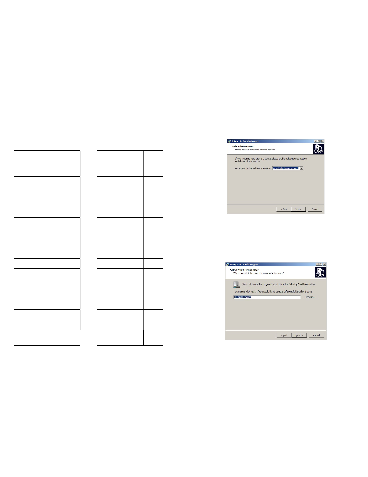
Logger Input Connector Wiring
Line Signal RJ-21
Pin
Line Signal RJ-21
Pin
1 Ring 1 9 Ring 9
Tip 26 Tip 34
2 Ring 2 10 Ring 10
Tip 27 Tip 35
3 Ring 3 11 Ring 11
Tip 28 Tip 36
4 Ring 4 12 Ring 12
Tip 29 Tip 37
5 Ring 5 13 Ring 13
Tip 30 Tip 18
6 Ring 6 14 Ring 14
Tip 31 Tip 39
7 Ring 7 15 Ring 15
Tip 32 Tip 40
8 Ring 8 16 Ring 16
Tip 33 Tip 41
GROUND 25,50
RJ-21 Taps and Adapters
DLI 16 CHANNEL LOGGER
15
logger. DLI has no “per user” or “per seat” licensing gimmicks. Feel free
to install as many copies as you need.
Save time and reduce complexity by only installing multiple device
support if you have more than one physical logger installed on this
computer. Select “No Multiple Devices…” if you are only installing one
physical 16-channel logger.
Next, select a start menu for program shortcuts:
Page 16
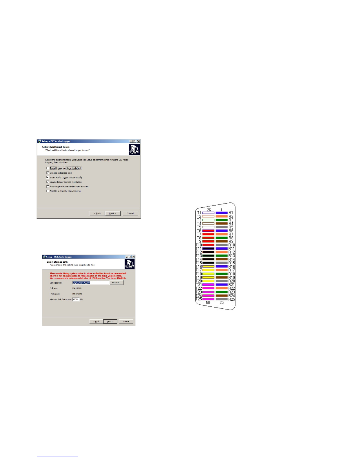
DLI 16 CHANNEL LOGGER
16
There are a few optional tasks. If this is a re-installation, you can select
“Reset logger settings to default”. You have the option of adding desktop
icon.
To record automatically after login, check ‘Start Logging Automatically”.
If a machine is left unattended, this ensures uninterrupted operation in
the event of a power failure and subsequent reboot. The logger service
watchdog will automatically restart the logger if it is closed for any
reason. You can also disable automatic disk cleaning (file deletion) here.
DLI 16 CHANNEL LOGGER
37
The connector itself is sometimes called an “AMP”, “CHAMP”, "blue
ribbon", or "gray phone" connector. RJ-21 connectors are polarized
(male and female) to prevent an installer from accidentally connecting an
internal extension to outside lines (or vice versa). Although the keying
is designed to prevent inverted installation, it is possible to force a plastic
connector on in reverse.
Pins 1 (ring) and 26 (tip) are considered position 1. Pins 2 (ring) and 27
(tip) are position 2 on thru twenty five pairs. Typically, only 24 pairs are
used (48 wires). Your 16 channel logger uses only the first 16 pairs (32
wires). The last pair on pins 25 and 50 (slate-violet and violet-slate
color) should be left as a spare pair. The spare pair keeps you from
having to run a whole new cable if a single pair fails elsewhere. DLI
Loggers use this pair as an earth ground connection. The logger can be
directly connected to most RJ-21x jacks via an Amphenol cable.
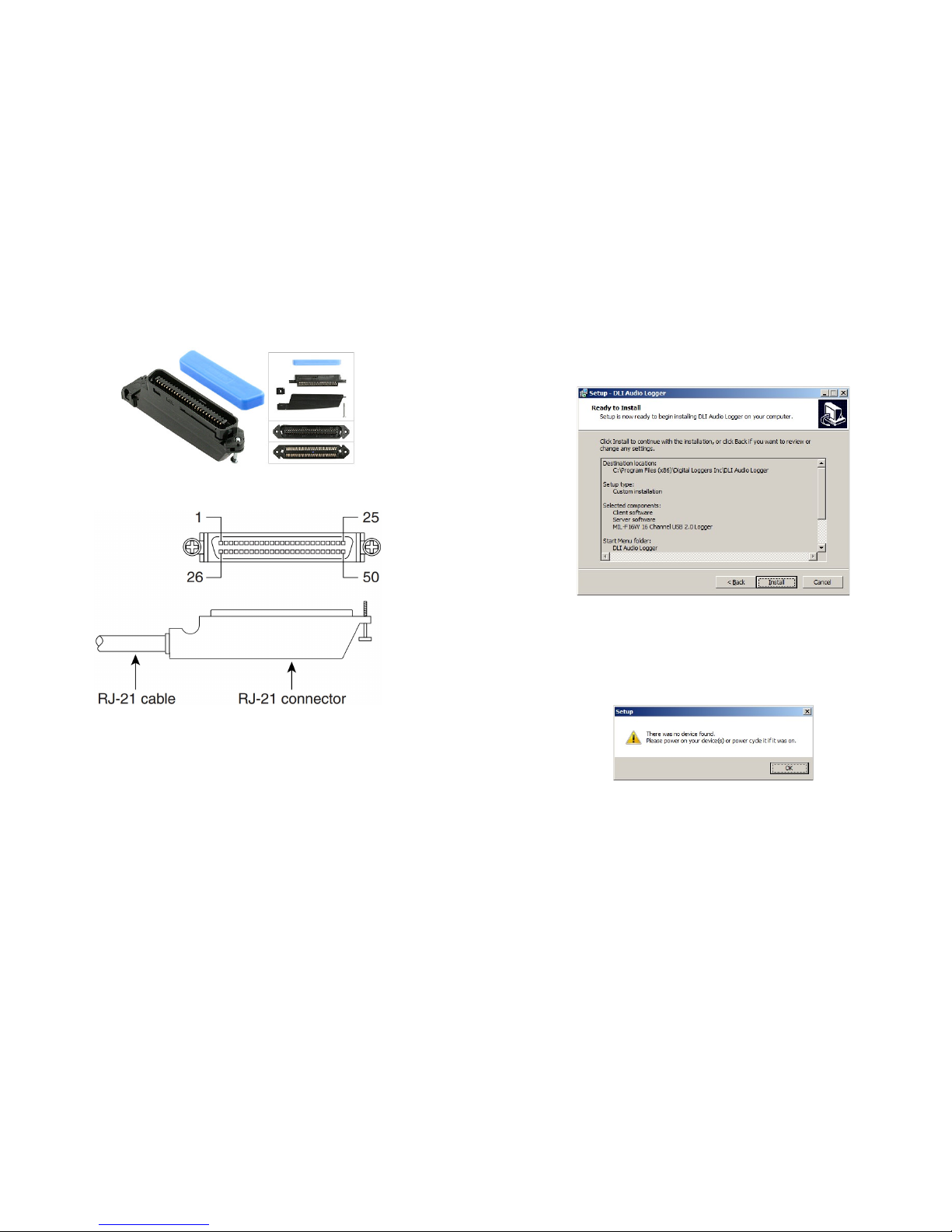
RJ-21 Color Code
RJ-21 cables follow the color code standard
used in all telecom wiring: Line 1 is the blue &
white pair, Line 2 is orange & white pair, etc. as
shown.
The logger pinout complies with this telecom
standard, but pins 17-24 and pins 42-49 (lines 17
to 24) are not connected.
The 25th pair provides an earth ground
connection.
When mounted correctly, a KT-66 block will have
line 1 on the uppermost pair, and line 25 on the
bottom of the block.
Page 17
DLI 16 CHANNEL LOGGER
36
Logger Input and RJ-21X Connection / Color Codes
Typical RJ-21 Audio Logger Mating Connector
An RJ-21 cable is a standardized phone cable uses 50 wires to transmit
up to 25 channels of digital or analog data. It is called an RJ-21x when it
is used as a "demarc" or attachment point for telcom equipment. The
"demarc" attachment point is commonly referred to as a "Network
Interface Device". An RJ-21X can be attached to a standard KT-66 or
110 type punchdown block, and is typically installed by the phone
company. In many installations, the customer is responsible for all wiring
after the RJ-21X, and the phone company is responsible for all wiring
before the RJ-21X. The circuits on an RJ-21X are provided on
numbered tip and ring positions on a miniature 50 pin connector of the
"AMP" type. These are very common connectors used on PBX, KSU,
PBC, and distribution frames.
DLI 16 CHANNEL LOGGER
17
Storage path is the final selection. We recommend you use a separate
hard disk or disk array for file storage. Keeping your audio files on a
separate drive will increase performance and reliability. If the disk
selected doesn’t have adequate space, a warning message appears.
At this point, you’re ready to start the installation… If you receive subsequent
security warnings from Windows, allow the system to install drivers. After the
installation is completed, it’s finally time connect the USB cable to the logger.
Power-up and attach the logger. Make sure the factory USB cable is used.
Connect directly to the host computer, not through a USB hub.
If the recording application couldn’t detect the logger, this warning appears.
Check power and USB cabling. Power-up and attach the logger. Make sure
the factory USB cable is attached.
Page 18
DLI 16 CHANNEL LOGGER
18
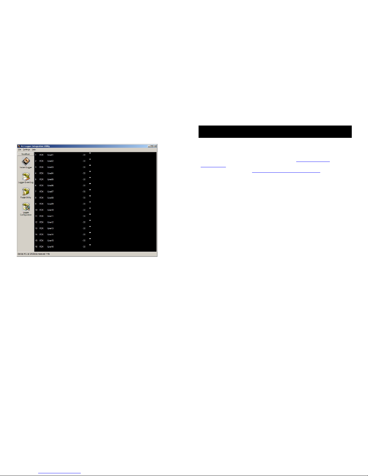
Once the application and drivers are properly loaded and the logger is
recognized, this screen appears:
Note that the level meters are low and uncolored. The application is not
recording at this point. When recording is not triggered, the VU meter
bars appear “grayed out”. While recording, the bars indicate the VU level
recorded in the file.
DLI 16 CHANNEL LOGGER
35
FAQs, Wiring Tips and Jack Pinouts
These pinouts and FAQs are included to assist in common installations.
A complete telecom wiring reference is beyond the scope of this guide,
so feel free to contact us at (408) 330-5599 or support@digital-
loggers.com for additional help. Please send your suggestions on
improving this manual to [email protected]
How do I connect the logger to a PBX?
There are three basic ways to link your logger to the outside world:
Record from incoming lines.
This method records from the outside party’s perspective. The recording
will follow the caller as he is transferred through the PBX. Incoming lines
are commonly recorded for quality assurance. For agent analysis or 911
call center recording, a console output or handset tap is usually a better
connection point. When recording from incoming lines, the level of the
calling and answering voices may differ. For a more balanced recording
level, use a handset connection or console output, or enable Auto Level.
Tap the handsets, AUX jack, dispatch console, or analog station
sets.
This method allows you to hear the recording from the agent’s
perspective. If you are recording in an E-911 dispatch environment, this
connection will listen-in from the dispatcher’s perspective. Recordings
made from these connections will typically include the phone
conversation, radio dispatch, etc. You will record everything the agent or
dispatcher hears. Most consoles have a dedicated recording output.
Handset taps may be connected to any phone, including VoIP
extensions. When recording from a handset, Caller-ID won’t be included
in the audio stream, but it may be logged using SMDR.
Connect to a PBX port.
This is a common method of connecting a logger in large installations
(100+ channels). One advantage of this connection scheme is that the
PBX can be used to switch the recorder to a large number of lines.
Another is that the logger can be switched to any recorder outside trunk
or inside extension. Think of this method as “conferencing in” the logger
with either an outside caller or an inside extension. This method requires
familiarity with PBX programming.
Page 19
DLI 16 CHANNEL LOGGER
34
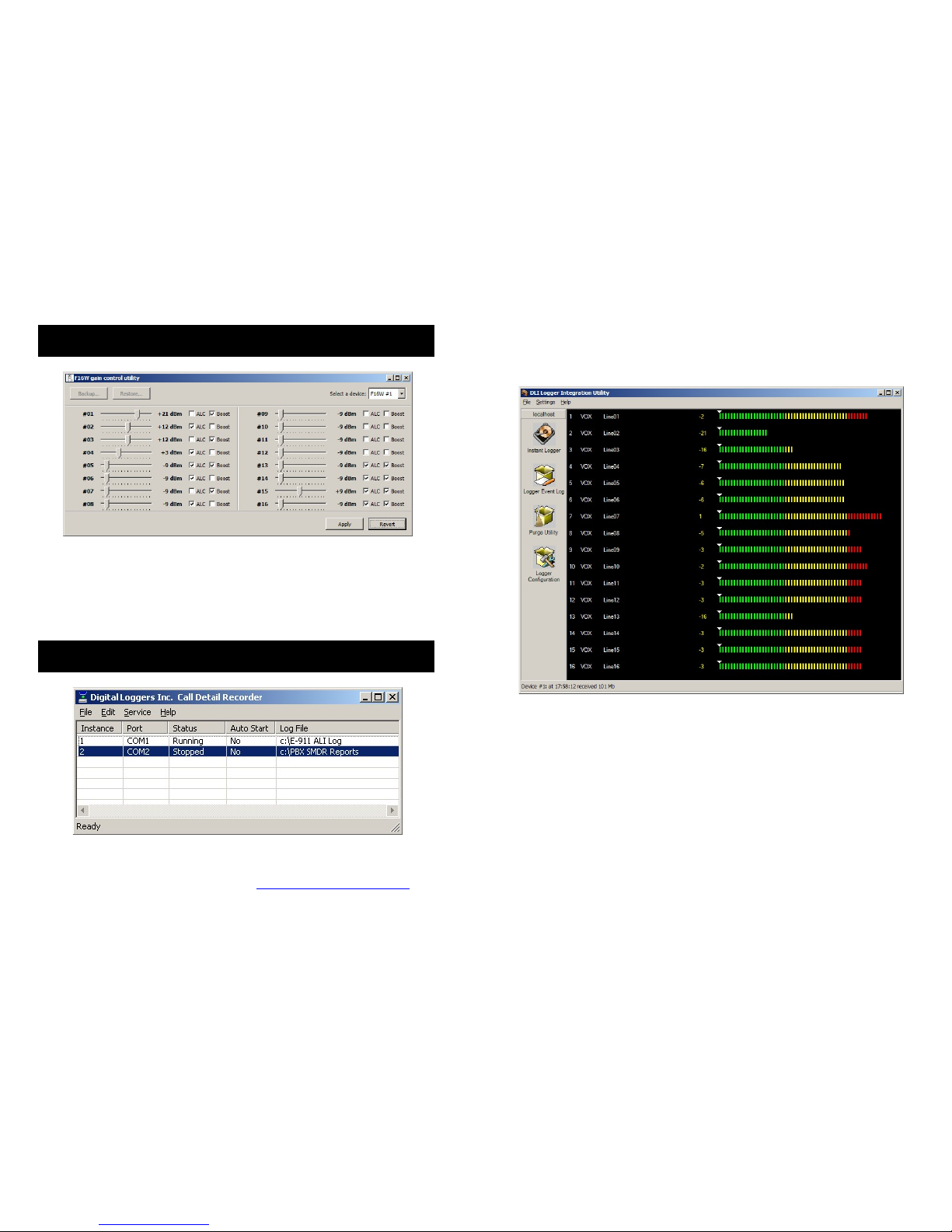
Remote Level Adjustment
For remote maintenance, a level adjustment utility is provided. Select
either ALC (Automatic Level Control) which is equivalent to pressing
Auto Level on the front panel, or use the slider for a fixed gain level.
Press Apply to commit changes. Level settings are stored in the logger
itself.
Recording SMDR, ANI, and ALI Streams
ANI, ALI, or SMDR data streams may be logged using our call detail
recorder utility. This utility logs up to 8 RS-232 serial ports
simultaneously. Download CDR from: digital-loggers.com/CDR.exe
DLI 16 CHANNEL LOGGER
19
When lines are active (recording), the audio level is displayed in color on
a bar graph like this:
This is the main user-interface screen which includes a graphical VU
meter and several other elements. There are several mouse shortcuts
on this screen. The most important are:
Clicking on Line Number
Clicking the line number spawns a window displaying the recording files
for that line. Files are organized in daily directories. Click on the file to
play it. This is a simple shortcut to play files.
Page 20
DLI 16 CHANNEL LOGGER
20
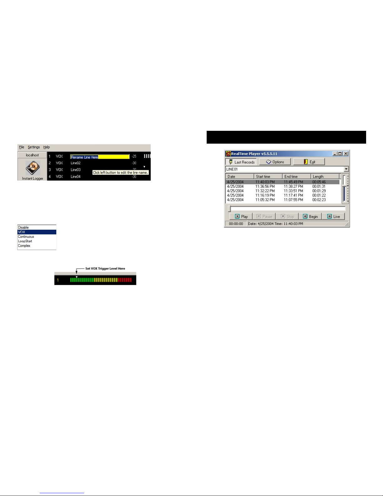
Left Clicking on Line Name
Clicking on the line name allows you to change it. The recording
directory name will also change. Press Enter to commit the change.
Right-Clicking on Line Mode
Clicking on line mode, ie. VOX allows you to select one of the five
recording modes described below:
Sliding (dragging) the VOX Trigger Level
The VOX trigger level is the minumim sound level that will start recording
in the Voice Operated Switch (VOX) recording mode. To adjust this level
in real-time, slide the arrowhead on the VU meter located to the right of
the line name. The VU meter is colored gray when recording is stopped.
When recording is started, the VU meter is colorized. To properly adjust
this level, hang up all phones and turn off all input sources. Check the
VU meter level. The level shown with phones “on hook” is called the
noise floor. Start with the VU trigger level about 10dBm above the noise
floor. Make test recordings. Adjust the level higher or lower as
necessary. The period of silence after which recording is terminated is
called the VOX timeout. This time value may be adjusted on the line
settings page.
DLI 16 CHANNEL LOGGER
33
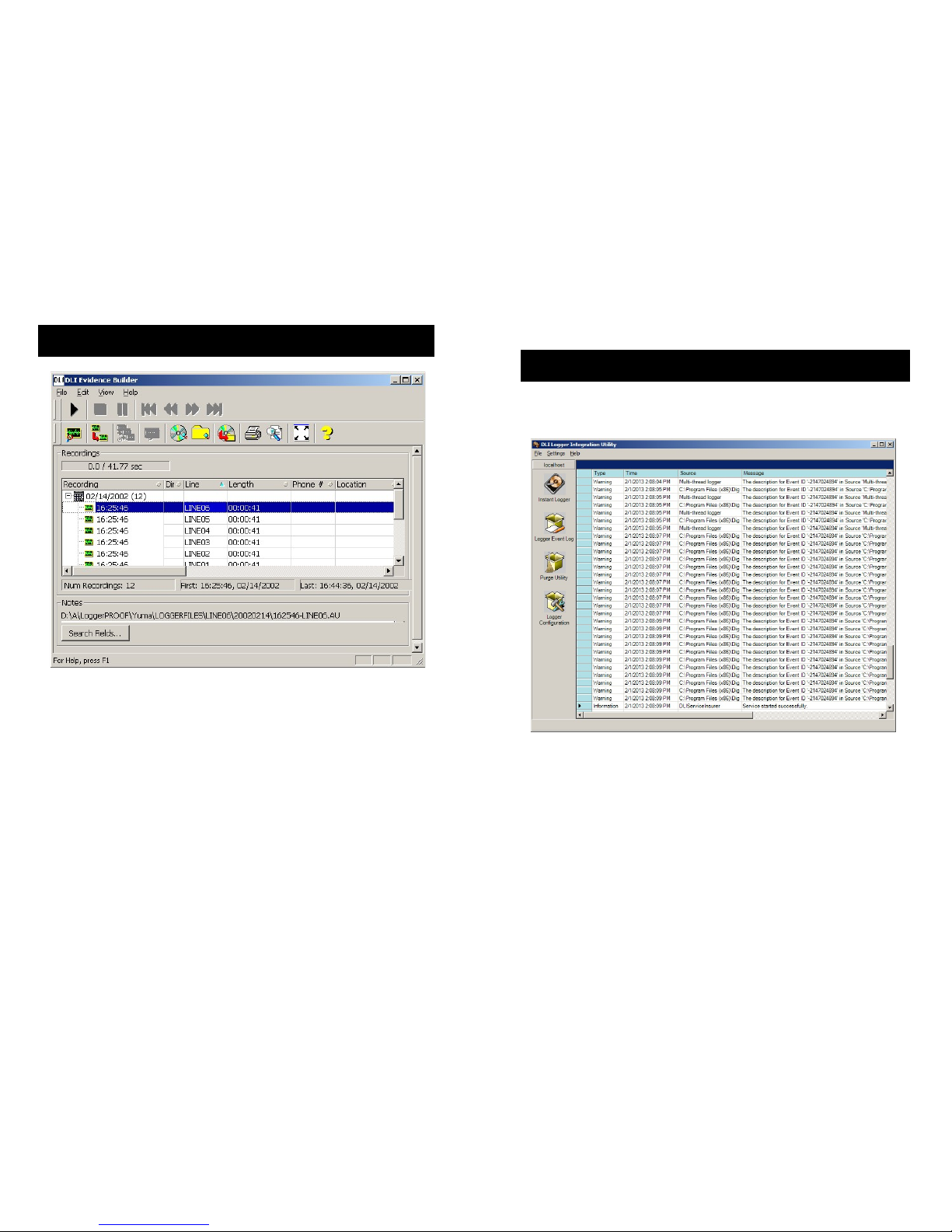
Network Real Time Player
To play a call recording, simply click on the recording file. This
plays a recording, but not in real time.
Remote users with access privileges may prefer to monitor calls in
real time via LAN or WAN connections using this application.
A Real Time Player application is provided on the distribution CD.
It’s downloadable from: digital-loggers.com/RTP.exe
To remotely monitor calls, load the Real Time Player application on a
workstation. Click Options. Use the browse button to select a
source directory with archived or incoming calls. Live calls are
highlighted. Select a call and press Play, or press Live to
continuously monitor calls as they come in. Windows security may
be used to selectively control access to specific lines.
Page 21
DLI 16 CHANNEL LOGGER
32
Evidence Builder Playback App
Evidence Builder Software is a powerful program used to locate and
analyze recordings. Load this on a workstation and point it at the
recording directories to analyze incoming calls, create call lists, sort
calls, and search by DTMF or Caller-ID. It also has unique abilities like
spreadsheet export, and the ability to add spoken audio time and date
stamps to recording files. You can easily concatenate multiple files and
launch audio editing programs from Evidence Builder.
To catalog files on a remote server, first create a path to the shared
recording directory. Be sure to use proper security. Map this to a drive
letter on your workstation.
Next, choose the Catalog Files From Hard Drive button and select the
top recording directory. The screen display can be customized by in
the Preferences menu. Click Help link for more detailed usage.
DLI 16 CHANNEL LOGGER
21
Logger Event Log
A detailed event log can be reviewed by clicking the Event Log icon:
Page 22
DLI 16 CHANNEL LOGGER
22
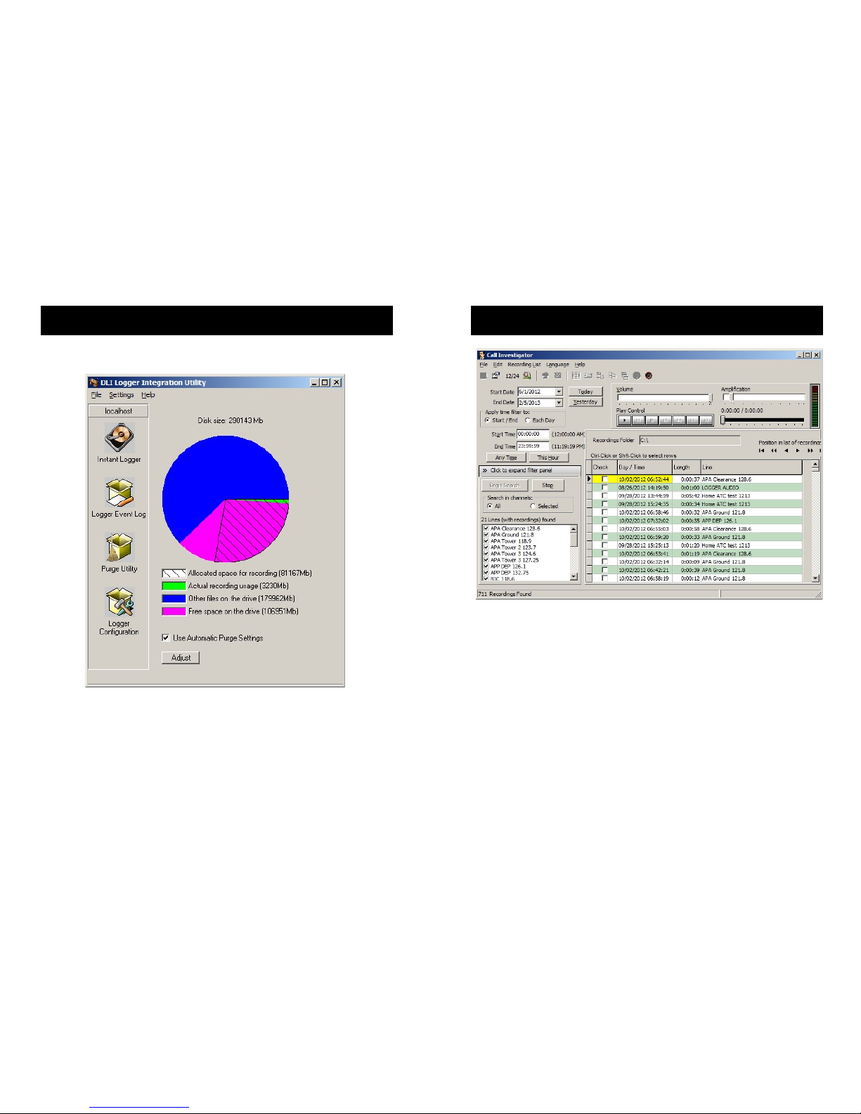
Purge Utility
Clicking the Purge Utility Icon brings you to this page.
A pie chart displays the used and allocated recording space. When the
disk space used for recordings exceeds the preset limits, older
recordings are automatically deleted to conserve space. With a large
disk, many customers never need to delete old calls. Best audio
streaming performance can be obtained using a separate disk for audio
files or a disk array for critical applications.
DLI 16 CHANNEL LOGGER
31
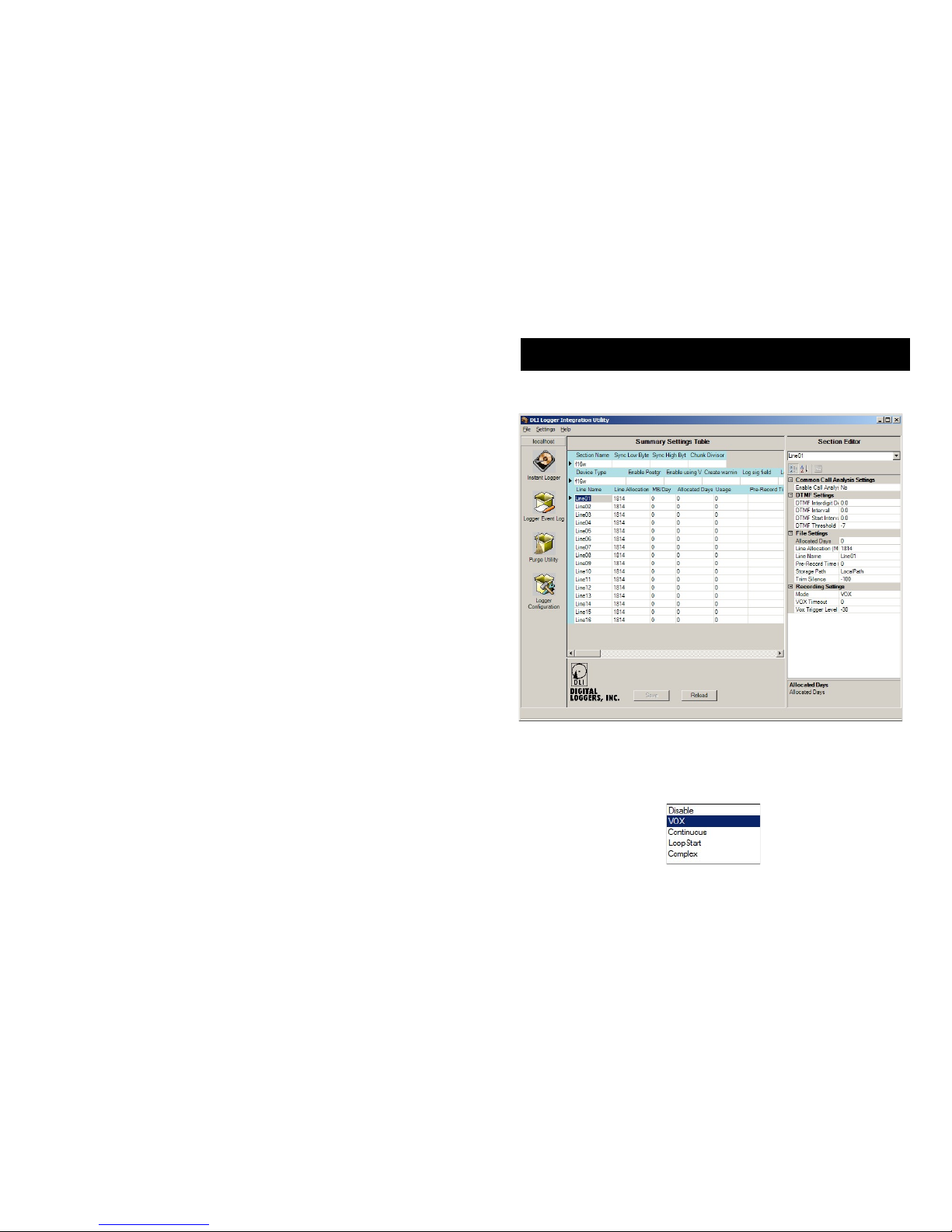
Call Investigator Playback App
Call Investigator is an efficient, easy-to-use utility for selecting, playing
and exporting audio files. Find it on the CD under “Install Playback
Software”
To catalog files on a remote server, first create a path to the shared
recording directory. Be sure to use proper security. Map this to a drive
letter on your workstation. Click Help link for more detailed usage.
Call Investigator can be found on the installation CD. Earlier versions
can be automatically updated over the web.
Page 23
DLI 16 CHANNEL LOGGER
30
The top of the screen shows the percentage used on the target disk.
Errors appear on the bottom of the screen.
The ‘Explore Calls’ Function
Click on the line name to explore the recording directory for that line.
Each line is stored in a separate folder, and each day is stored in a
subfolder. The file names correspond to the recording start time. From
here, you can edit, copy, or transfer files using Windows Explorer by
clicking the right mouse button. Although clicking on the file is often the
easiest way to play individual recordings, several applications are
available to manage, sort, and locate recordings.
DLI 16 CHANNEL LOGGER
23
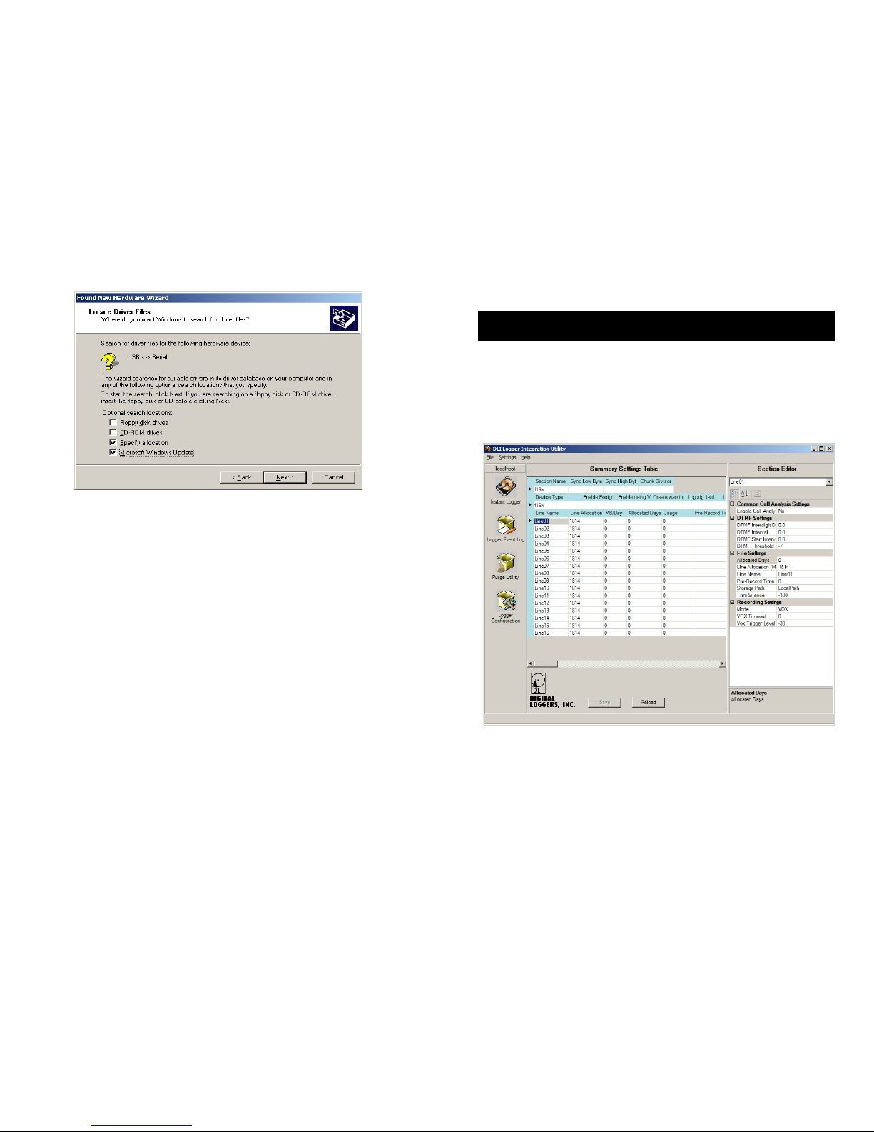
Logger Configuration Page
Clicking the Logger Configuration icon brings you to this page:
To adjust the settings for each line, first click on the line name. The
settings for that line appear in the right window pane. The default
settings are good for most installations, but the recording trigger mode
often needs to be adjusted. Five modes are available:
Disable
Page 24
DLI 16 CHANNEL LOGGER
24
Prevents recording for this line. Select this for unused lines.
VOX
Starts and stops recordings automatically based on the sound level on
that line. Use this setting for all dry lines, such as radios and handsets.
In VOX mode, you will need to adjust the VOX Trigger Level to start
recording at a trigger level specified in dBm.
Continuous
Use this always-recording setting to record a line 24x7.
LoopStart
Select loop start for wet lines. This mode monitors the DC voltage on the
line to determine if a phone is off-hook.
Complex
Complex mode is used for wet lines and will “pre-record” when sound is
detected prior to a phone going “off hook”. It’s useful for catching callerID on wet lines. Caller ID is normally transmitted between the first and
second ring.
Pre-Record Time
Selecting a pre-recording time will include audio before the VOX or Loop
Start trigger was detected. This is useful for recording Caller ID (CID).
Trim Silence
By definition, a VOX controlled recorder will not stop recording until a
period of silence occurs. To trim this silence data from the end of a
recording file, select a trim level in dBm using the Trim Silence setting.
DTMF Settings
DTMF settings do not normally need to be changed if input levels are set
correctly. If you must increase recording gain to the point at which
clipping distortion occurs, these settings will need to be reduced.
Most other settings are self-explanatory. Be sure to click the “SAVE”
button to commit changes. Feel free to contact us at (408) 330-5599
with questions and suggestions.
DLI 16 CHANNEL LOGGER
29
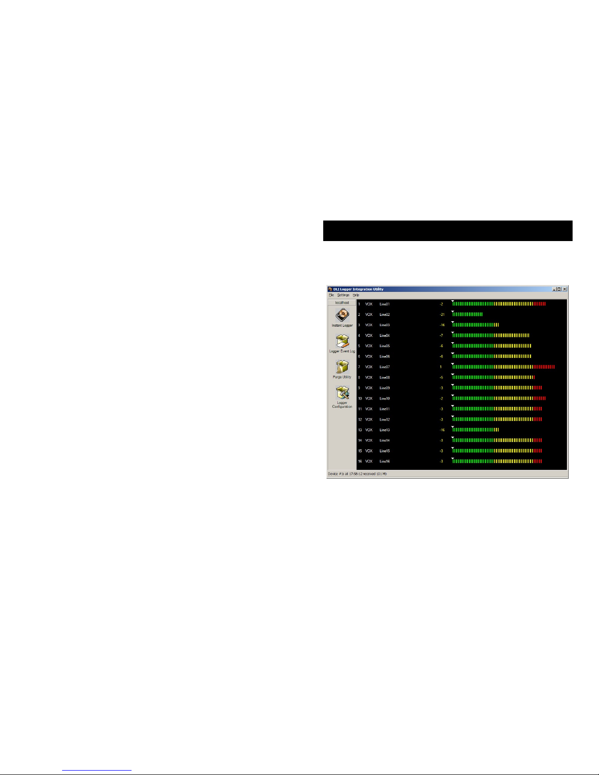
Using the Logging Application
Click on the DLI Audio Logger icon to start the application. The main
screen appears:
The recording mode for each line, ie VOX, LOOPSTART (abbreviated
LPS) or OFF is displayed to the left of the line name. The recording
level for each line appears decimal and color bar graph format when
that line is recording.
Adjust the gain controls so that the highest levels (ie. dialing) peak at
around 0dBm. Setting the level too high will cause distortion and
prevent touch tones and Caller-ID from being properly decoded.
Click on the line name to explore the recordings for that line.
Page 25
DLI 16 CHANNEL LOGGER
28
Line Name
Choose “PSAP Desk 1” or a similar useful extension name if you have
a channel assigned to a single speech path in your PBX. If you have a
particular phone number assigned to that timeslot, it may be useful to
include the number in the line name, such as “DLI Main Hunt Group
(408) 330-5599”. If you are recording from an outside trunk, a separate
program will allow you to search by Caller-ID or DTMF signaling after
recording. Since this Line Name will be used as a recording directory,
be careful not to include disallowed characters, such as “/” “,” or “\”.
Maximum Megabytes
The logger can automatically delete old calls to conserve the amount of
disk space used by each channel. This setting controls the maximum
amount of disk space used by each channel. When disk space is low
and this threshold setting is reached, oldest calls are automatically
deleted to free disk space. To turn this feature off, set this field to “0”.
If you specify a maximum, the logger will check disk space periodically.
If recording size exceeds your setting, the logger will automatically
delete files starting with the oldest day. The logger will continue
deleting calls until disk usage reaches the setting. It’s important to set
this so that the total space used does not exceed the available disk
space. You may want to run the logger for a few days, and then
evaluate the usage on a line-by-line basis.
Enable Call Analysis
If Caller-ID (CID) and touch tone dialing (DTMF) tones are present in
the recordings, the logger can analyze the audio to extract this
information. Having the number dialed makes it easier to organize and
find calls. CID is a paid subscription service in most areas. CID is not
available on a handset connection, or if a phone is answered before the
second ring. Enable analysis to decode these tones.
DLI 16 CHANNEL LOGGER
25
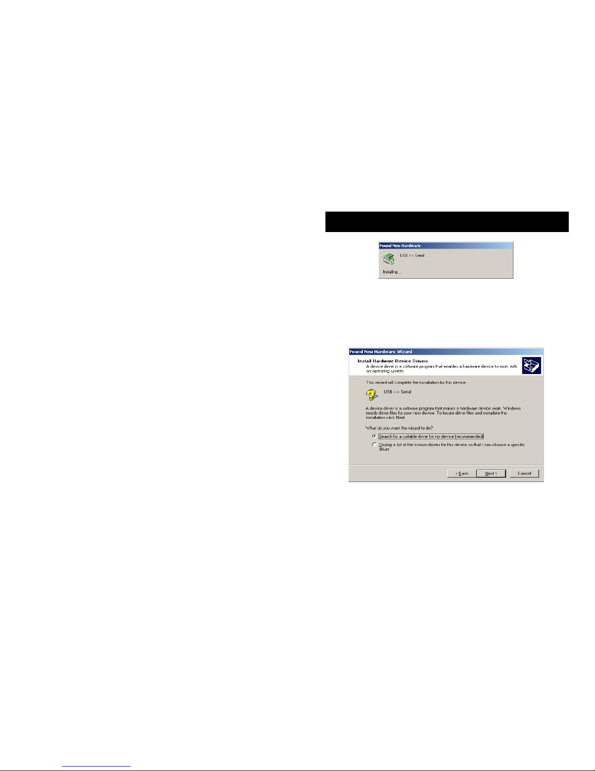
USB Serial Driver Installation
If you have successfully installed the recording application before
connecting the logger, skip this section. If you connected the USB cable
–before- installing the software, Windows will guide you through a USB
serial driver installation process. We suggest you cancel this process,
disconnect the logger and install the driver CD, but here is the procedure
for manual installation:
If you have already started the process, you’ll need an internet
connection to load the driver. Choose the Search option first.
Page 26
DLI 16 CHANNEL LOGGER
26
Next, choose “Windows Update” to download the latest driver.
Click “Next” to finish. This process may repeat up to two times for each
logger attached.
DLI 16 CHANNEL LOGGER
27
Important Configuration Settings
Each of the 16 input channels corresponds to one recording directory.
Within each channel directory, the logger creates a subdirectory for
each day of recordings.
To change settings for a particular channel, click the small + symbol to
the left of the line name. The settings for that channel are displayed.
The most important settings are:
Record Trigger Mode
Set this to VOX for normal operation. Choose LOOPSTART (LPS) for
line voltage sensing, or COMPLEX for VOX operated pre-recording on
Loop Start Lines.
 Loading...