

DLE 85 User Manual

DLE
-
85
Operator’s Manual
Specifications
Displacement:
Performance:
Idle Speed:
Ignition Style:
Recommended Propellers:
Sparkplug Type:
Diameter × Stroke:
Compression Ratio:
Carburetor:
Weight:
™
1
© 2014 Hobbico®, Inc. DLEG0085 Mnl
84.88cc 5.18 cu in
8.5HP/7,500 RPM
1,5 00 RP M
Electronic Ignition
25×10, 26×9, 27×8
NGK CM6
(Gap) 0.018in.– 0.020 in. [0.45mm – 0.51mm]
2.05in(52mm) × 1.57in(40mm)
9.5: 1
DLE with Manual Choke
Main Engine – 68oz [1930g]
Muffler – 8.8oz [250g]
Electronic Ignition – 4.58oz [110g]
Engine Mount Standoffs – 28oz [454g]
87− 93 Octane Gasoline with a 30:1
Fuel:
gas/2-stroke (2-cycle) oil mixture
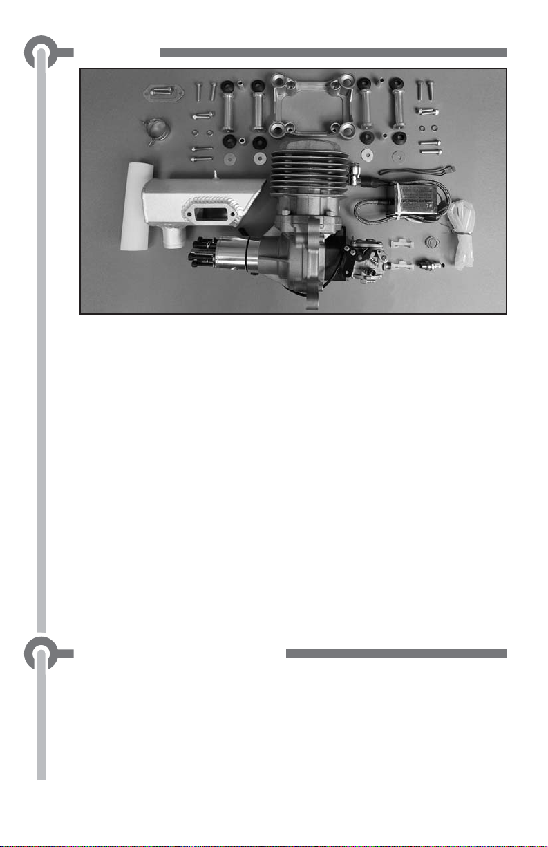
Parts List
(1) DLE-85 Gas Engine with DLE Carburetor
(1) CM6 Spark Plug with Ignition Wire Spring
(1) Muffl er w/Gasket
(1) 30mmx120mm Exhaust Tube with Clamp
(2) 5x20mm SHCS (muffl er mounting)
(1) Electronic Ignition Module w/ Additional Tachometer Lead
(4) 68mm Engine Mounting Standoffs
(1) Isolation Engine Mount
(8) Isolation Mount Grommets
(4) Isolation Mount Spacers (5mmX9mmx15mm)
(8) 5x25mm SHCS (engine mounting)
(4) 5x20mm SHCS (engine mounting)
(4) 5x10mm Washers
(4) 5x19mm Flat Washers
(6) 5x50mm SHCS with 5mm Lock Washers & Flat Washers (propeller mounting)
(1) Silicone Pick-up Wire Cover/Ignition Wire Cover
(1) Red Three Pin Connector Lead w/Pig Tail (for ignition switch)
(2) Three Pin Connector Securing Clips
(1) DLE Decal (not pictured)
Safety Tips and Warnings
● This engine is not a toy. Please place your safety and the safety of
others paramount while operating. DLE will not be held responsible
for any safety issues or accidents involving this engine.
● Operate the engine in a properly ventilated area.
●
Before starting the engine, please make sure all components
including the propeller and the engine mount are secure and tight.
It is strongly recommended that a screw sealant is used (Great
2
Planes® Threadlocker GPMR6060) during engine installation.

● During the break-in period, it is recommended that the engine be
installed on the aircraft or a test stand with an appropriate shock
absorber. Otherwise it is probable that vibration could rebound
back to the engine and serious damages may occur during the
break-in period.
gallons you run through the engine.
● For your safety and the safety of others, please do not stand in
front of or in line with the propeller when the engine is running.
Keep onlookers away from the running engine, especially small
children.
● Always use a balanced spinner and a balanced propeller. An
unbalanced spinner and propeller combination will cause high
levels of vibration and may cause the propeller shaft to break.
Always use a lightweight spinner on your engine. Lightweight
spinners are considered to be those with a cone wall of 1mm
or less. Heavy spinners could cause the propeller shaft to break.
Securely tighten the spinner and propeller on the engine to prevent
it from being thrown off the engine while running.
● Never use a propeller that has hit the ground. Even though it may
look good from the outside, it may be cracked on the inside which
may cause it to disintegrate while in use. Do not use a nicked,
cracked or split propeller.
● Keep foreign objects away from the propeller. Make sure that
nothing can be “sucked in” by the propeller.
● Never start the engine on loose gravel or sand.
● Do not attempt to stop the engine by throwing anything into the
path of the propeller.
● Make sure the fuel line is well-secured to the engine and to the fuel
tank so that it won’t come off in fl ight.
● Do not use silicone fuel line because it will be dissolved by the fuel.
Use gasoline approved vinyl or neoprene rubber fuel line. Always
secure the fuel line away from the cylinder head. The engine’s heat
can damage the fuel line.
● Never touch the engine immediately after a run. The engine will
be hot.
● Before transporting your model, remove all the fuel from the fuel
tank and fuel lines.
● Always use high-quality oil intended for 2-stroke (2-cycle) engines.
It's a good idea to use a petroleum-based 2-cycle motor oil like
Lawn Boy All Season - Ashless oil for the break-in period.
● Do not install your throttle servo inside the engine compartment.
Doing so could cause radio interference. Install all electronic radio
3
devices at least 305mm [12"] away from the engine.
Break-in should be considered about the fi rst 3-5

● The throttle and choke pushrods should be non-metallic.
●
In case the engine is not to be used for more than a month, drain
the fuel tank and remove any fuel from inside the carburetor. Do this
by running the engine at idle until it quits by running out of fuel.
Keeping gasoline inside the carburetor over an extended period of
time will damage the diaphragm valve and clog passages inside the
carburetor. Because the carburetor is more complicated than those
used in glow engines, keep the fuel clean by using a fuel fi lter. Use a
fi lter intended to be used with gasoline engines. Metal fi lters intended
for glow engines are too coarse and will not screen out fi ner particles.
● Always fi lter your fuel by using an appropriate fi lter before putting
it into the airplane’s fuel tank.
● Gasoline is extremely fl ammable. Keep it away from an open fl ame,
excessive heat or sources of sparks.
● Do not smoke near the engine or the fuel tank.
● This engine was designed for use in a model aircraft. Do not
attempt to use it for any other purpose.
● Always install an ignition system on/off switch on the aircraft used.
● Caution: Running the engine with a lean gas mixture will cause
the engine to overheat and burn the electrode of the spark plug.
Pay close attention to the High-Speed Needle adjustment. Running
the engine with the proper gas mixture will make the spark plugs
appear yellow at the ignition point.
● For optimum performance please use fresh or recently purchased
87– 93 octane gasoline with a 30:1 gas / oil 2-stroke (2-cycle) mixture.
GAS/OIL Mixing Chart
1 Gallon Gasoline (128 fl oz/3.78L) / 2-Cycle Oil
(4.26fl oz /125.68ml) = 30:1 ratio
● Excessive running of the engine at idle speed can result in a
seriously carbonized spark plug.
●
Keep the surface of the engine clean to ensure proper heat dissipation.
● To avoid permanent damage to the electronic ignition system,
NEVER rotate the propeller on your DLE engine with the
electronic ignition system switched on and the plug not installed
in the plug cap.
●
If you choose to use the optional TX activated gas engine kill switch
(DLEG9205) it is strongly recommended that you install the TX
activated kill switch between the with a manual on/off switch and
the ignition. The manual on/off switch provides an added safety
feature in the event the TX activated kill switch does not function
properly. This is especially important during the starting sequence
as it requires the manual on/off switch to be in the ON position
4
before ignition can occur.
Installation Instructions
Prepare the engine for installation
1. Check to see that all screws and bolts are tight. Check carefully
for any cracks, broken, or missing parts. Tighten or replace any
damaged or missing parts before proceeding.
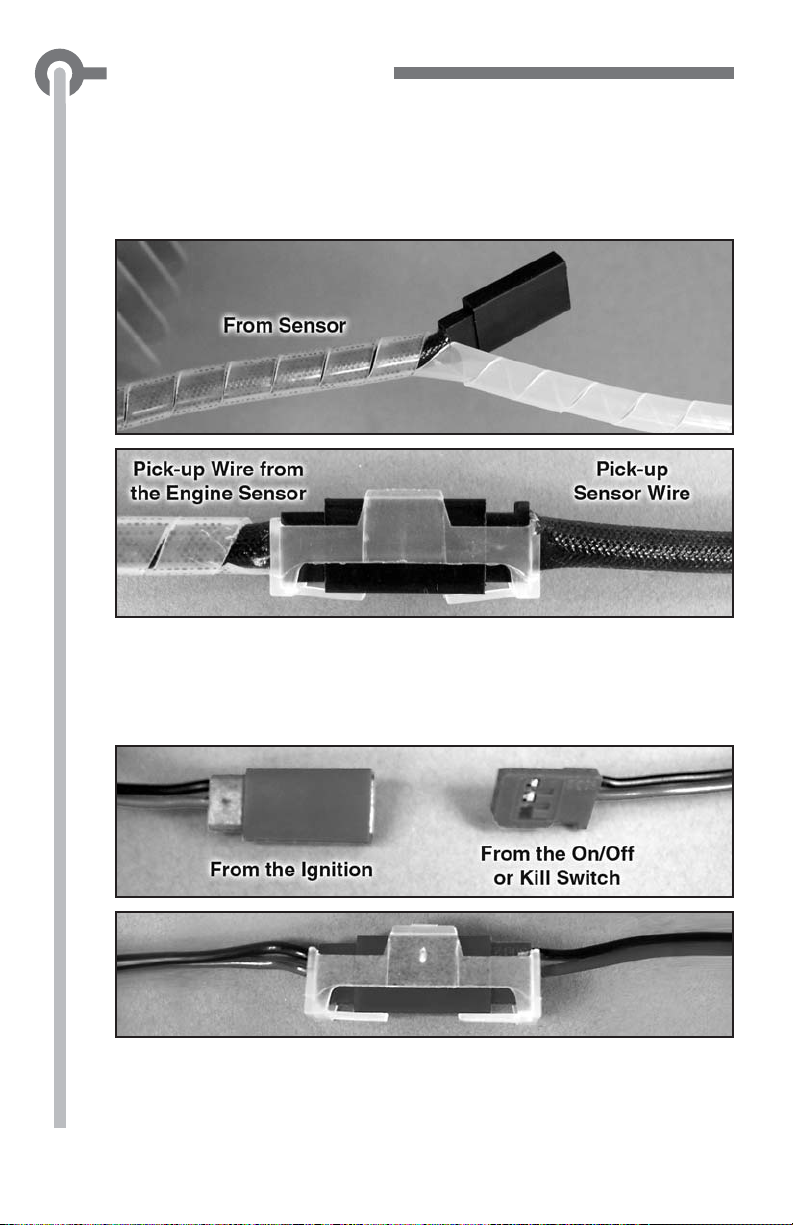
2. Install the silicone wire cover over the pick up lead coming from
the engine (cut the excess silicone wire cover) and connect the lead
to the pick–up lead from the Electronic Ignition Module. Secure
the connection with the included three pin connector securing clip.
3. Connect the manual on/off switch lead to the red connector from
the electronic ignition system using the lead from the kill switch or
with the included three pin connector with pig tail. Use one of the
included three pin securing clips to secure the connection.
5
4. Connect the ignition module battery to the kill switch. Any
4.8-8.4 V, 1000 mAh and above capacity battery will work well for
this. Use heat shrink tubing to secure this connection. Optional:
Install the TX activated gas engine kill switch (DLEG9205) between
the manual on/off switch and the ignition as shown above. This is
especially important during the starting sequence as it requires
the manual on/off switch to be in the ON position before ignition
can occur. The kill switch LED should be installed on the exterior of
the aircraft so that it’s visible from the front of the aircraft. This is to
ensure that the person starting the engine is aware that the ignition
is armed. If properly installed as shown above, an illuminated red
LED indicates that that the ignition is armed.
5. Install the ignition on/off switch on the aircraft so that it is easily
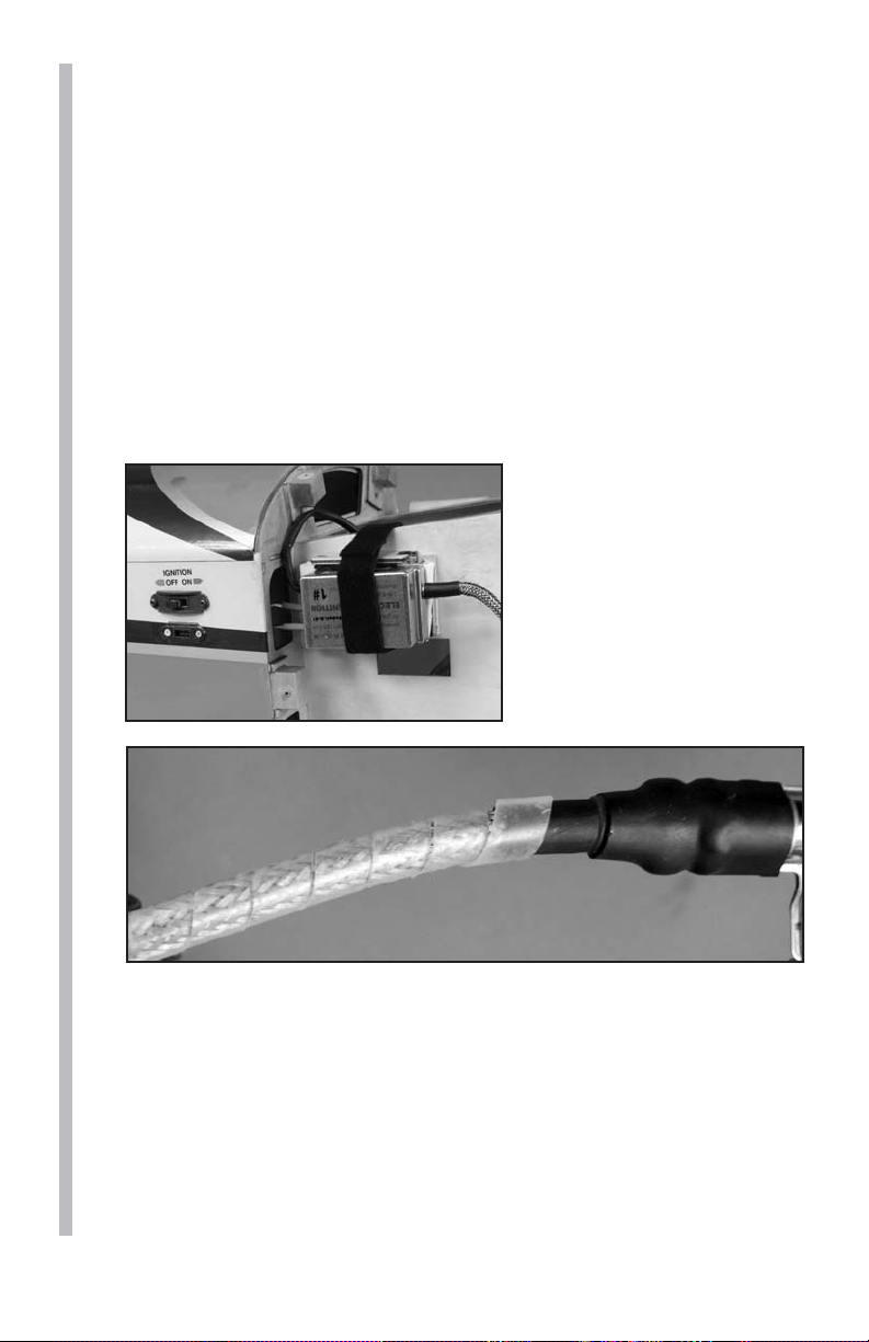
accessible through the cowling or the fuselage.
6. Install the ignition module
and battery securely in the
airplane forward area. It is
recommended that a thin
piece of foam rubber is
placed between the module
and the mounting surface
and that Velcro® strap is used
to hold the module in place.
7. Install the remaining silicone wire cover over the ignition wire.
8. Install the spark plug into the engine head (7– 8 lbs torque). Do
not overtighten.
6
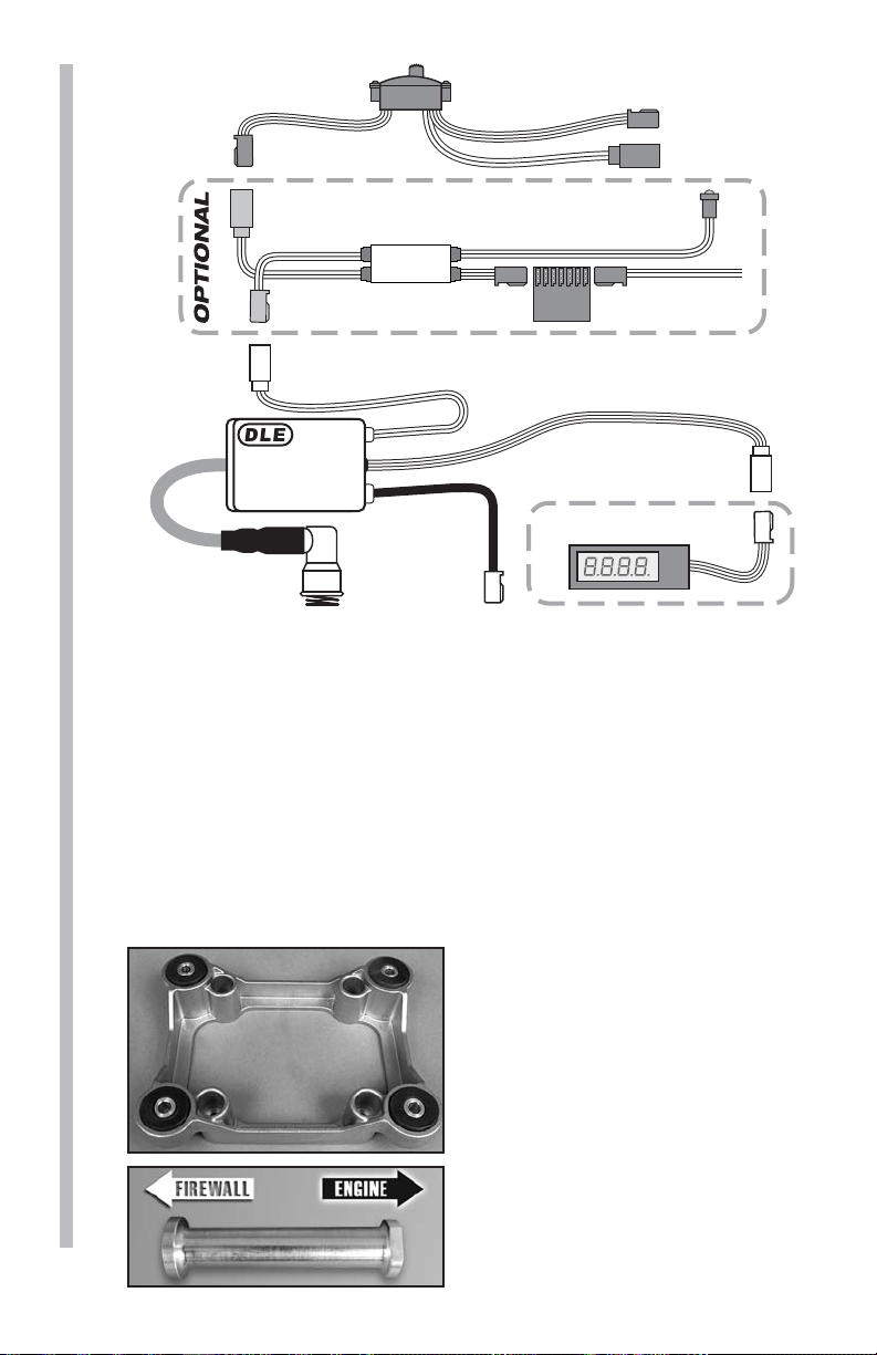
Switch (Not included)
Charge Lead
Battery Lead
Battery Lead
ELECTRONIC IGNITION
Ignition Wire
(To Spark Plug)
Ignition
Ignition
Ignition Control Switch Wire (To On/Off Switch)
SYSTEM
OPTO Gas Engine Kill Switch
(DLEG9205, not included)
KILL
SWITCH
Rx
Tachometer Lead/
RPM Signal Output
Tachometer
Pick-Up
Sensor Wire
(To Sensor
On Engine)
(Not included) DLEG5525
OPTIONAL
Rx Batt
Lead
Installing the DLE-85 on Your Airplane
Note: The DLE-85 must be installed on at least a 9.5mm [3/8"]
thick 5-ply plywood fi rewall. The fi rewall must be securely glued to
the airplane. Use triangle stock and pin the fi rewall with hardwood
dowels to reinforce the fi rewall glue joints. Never install the
DLE-85 onto a fi rewall thinner than specifi ed because it may fail
due to the power of the engine.
Note: The length of the engine from the back of the engine mount
to the propeller drive washer is 7.87" [200 mm].
1. Use the supplied template (on the back cover of this manual) to
drill the engine mounting bolt holes.
2.
Install (4) 5mm blind nuts on
the back side (non-engine side of
the fi rewall) in the holes drilled in
step 1.
3. Install the 8 grommets and
4 spacers to the anitvibration
mount as shown.
4.
Install the 4 standoffs to the
engine in the orientation shown
using the (4) 5x20mm SHCS and
5mm washers. Be sure to use
7
threadlocker.
LED
5.
Install the standoffs to the mount by inserting (4) 5x25mm SHCS
and (4) 5x19mm fl at washers through the backside isolation mount.
Mount the engine standoffs and isolation mount to the fi rewall by
installing the (4) 5x25mm SHCS through the isolation mount and
into the fi rewall into the 5mm blinds nuts (not included). Note:
The proper orientation of the mount can be seen on the front of
this manual. Be sure to use threadlocker.
6.
Mount the engine to the aircraft by installing the (4) 5x25mm
SHCS through the isolation mount and into the fi rewall. Secure
the SHCS to the 5mm blind nuts (installed on step 2). Be sure to
use threadlocker.
7. Install the fuel tank in the airframe. Use only 1/8" [3.175 mm]
gasoline-safe fuel lines and a gasoline safe fuel tank stopper. One
line should go to the carburetor and the other is to be used as a
vent (a vent line is simply an open ended fuel line from the fuel
tank which exits the engine compartment or the fuselage; most
vent lines exit at the bottom of the fi rewall).You can fi ll the tank
by using the carburetor line as fi ll line if you have access to it or
install a third line to be used as fi ll line. Installing a third line is
the cleanest and easiest way to add fuel. An alternative fueling set
up is a 2-line system with a T-fi tting approved for gasoline use. Be
sure to use a fi ller plug with either a 2 line or 3 line set-up.
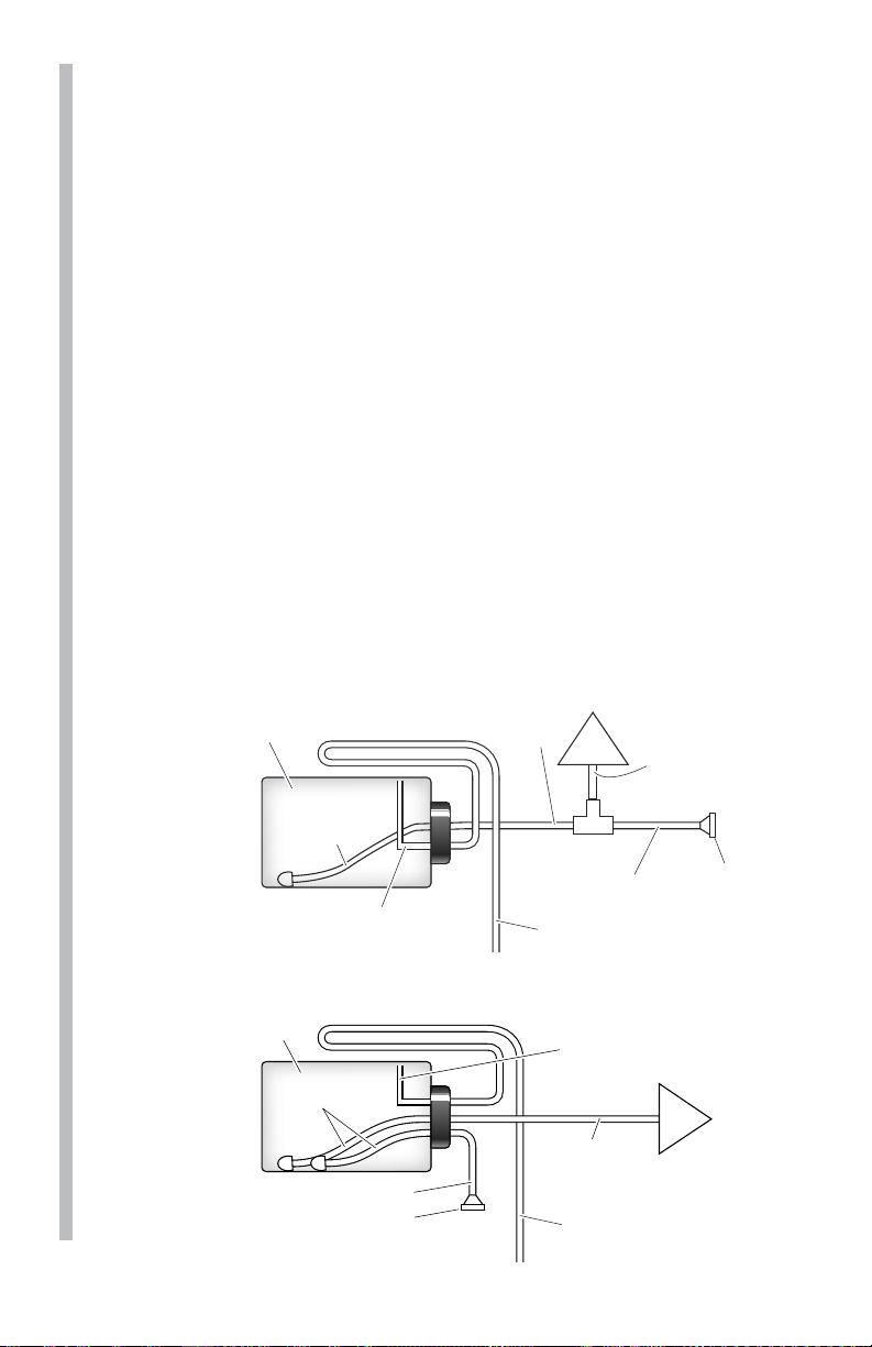
Fuel Tank
2-LINE
SET UP
Route to top-front of fuel tank interior,
to prevent siphoning (2-Line Set-up)
3-LINE
Clunk Line
Drain/Vent Pressure Relief Line
Fuel Tank
Clunk Lines
SET UP
Fuel fill line
Plug
Supply Line
to T-Fitting
Carb
T-Fitting
This line must be extended
to exit the bottom of the aircraft.
Drain/Vent Pressure Relief Line
Route to top-front of fuel tank
interior, to prevent siphoning.
Supply Line
to Carburetor
This line must be extended
to exit the bottom of the aircraft.
Make connection line
between T-Fitting and
Carburetor as short
Fuel fill line
as possible.
Filler Cap
or Plug
Carb
8
 Loading...