

Page 1
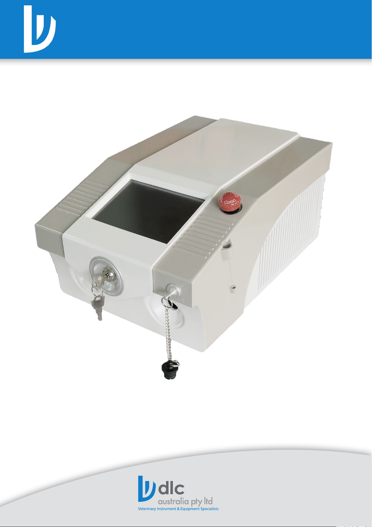
PD030 DIODE LASER MANUAL
30W Diode Laser Surgical System Manual
Please read the manual carefully before operating, and
keep this manual for future reference.
For further information please call
1300 785 401 - Northern Oce
1300 785 405 - Southern Oce
Email: [email protected]
Model: PD030
DLC Australia Pty Ltd 1 www.dlc.com.au
www.dlc.com.au
DLC Australia Pty Ltd 1www.dlc.com.au
Page 2

PD030 DIODE LASER MANUAL
Table of Contents
30W DIODE LASER SURGICAL SYSTEM.................................................................................... 1
Product Manual .............................................................................................................................. 1
Table of contents.............................................................................................................................. 2
Safety Guidelines............................................................................................................................ 3
Preface................................................................................................................................................ 4
1. Operation principle .................................................................................................................. 5
1.1 Principle of diode laser surgical system..................................................................... 5
1.2 System description............................................................................................................. 5
1.3 Main cabinet......................................................................................................................... 5
1.3.1 Diode laser and aiming beam............................................................................. 5
1.3.2 Power supply.............................................................................................................. 5
1.3.3 Main control panel................................................................................................... 5
1.3.4 Power meter............................................................................................................... 6
1.3.5 Foot switch................................................................................................................. 6
1.3.6 Fiber.............................................................................................................................. 6
2. Components.................................................................................................................................. 6
3. Pre-startup preparations.......................................................................................................... 7
3.1 Unpacking and inspection................................................................................................ 7
3.2 Checking power voltage................................................................................................... 7
3.3 Connecting power cable................................................................................................... 7
3.4 Footswitch Connection..................................................................................................... 7
4. Operation Instruction............................................................................................................... 8
4.1 Power on................................................................................................................................ 8
4.2 Self-detecting...................................................................................................................... 9
4.3 Parameter Setting............................................................................................................... 9
4.4 Change Status and Emit................................................................................................... 10
4.5 Automatic Calibration....................................................................................................... 11
5. Fiber Cutting................................................................................................................................ 12
6. Protection...................................................................................................................................... 12
6.1 Overheat Protection........................................................................................................... 12
7. Precautions................................................................................................................................... 13
8. Maintenance................................................................................................................................. 13
8.1 Cabinet cleaning................................................................................................................... 14
8.2 Power calibration................................................................................................................. 14
8.3 Fuse replacement................................................................................................................. 14
9 Accessories..................................................................................................................................... 15
10 Technical Specication............................................................................................................ 15
11. Warranty & Service................................................................................................................... 16
12 Structure....................................................................................................................................... 17
13 Label Explanations..................................................................................................................... 18
DLC Australia Pty Ltd 2 www.dlc.com.au
Page 3

PD030 DIODE LASER MANUAL
Safety Guidelines
The following information is provided for the correct utilization of diode laser surgical
system. The information includes not only the accident protection regulations the
products comply with, but also the eective precautions regarding proper use of the
products.
The safety regulations that PD030 series diode laser surgical system comply with can be
grouped under 3 categories:
1. Electric safety regulation
2. Laser radiation safety regulation
3. Electromagnetic radiation safety regulation
These safety regulations comply with the following standards established by IEC:
IEC 60601-1
Medical electric equipment part 1: General requirements for safety
IEC 60601-1-2
Medical electric equipment general requirement for safety collateral standard:
electromagnetic compatibility requirement and test
IEC 60601-1-4
Medical electric equipment general requirement for safety collateral standard:
programmable medical electric equipment
IEC 60602-2-22
Medical electric equipment part 2, specic safety requirement on diagnosing and
treatment laser equipment
IEC 60825-1
Radiation safety for laser product, equipment classication requirement and user’s
guidance.
Although PD030 series diode laser surgical systems are designed according to accident
prevention regulations, only a proper and careful use can guarantee safety. For eective
precautions, please refer to next part.
The EMC performance of this system has been evaluated and complied with En 60601-1-2.
Better use this system in an environment free of strong electromagnetic.
DLC Australia Pty Ltd 3 www.dlc.com.au
Page 4

PD030 DIODE LASER MANUAL
Preface
The PD030 diode laser surgical system is an intelligent laser treatment instrument. This
product is featured by compact structure, beautiful appearance, reliable performance,
convenient operation and perfect safety. The technical specications of the product have
achieved the advanced international standard.
The diode laser has a high electro-optic conversion rate, producing little excess heat, so
it does not require a large water cooling system like Nd:YAG or CO2 lasers, which makes it
small in size and light in weight. Meanwhile, the diode laser does not contain high-voltage
high-temperature components, providing longer service life, more stable power output,
lower power consumption and more exible application.
The PD030 surgical diode laser has two operation modes – continuous mode and repeat
pulse mode. Optical bers with diameter of 200,400,600,800,1000um can be used as its
delivery system. The diode laser has quick vaporization eect and good hemostatic eect.
The laser beam has no electric stimulation to nerve and tissue, there will be little injury,
little pain and few complications on the patient, and the hospitalization is short. The laser
can match all kinds of endoscopies by using optical ber of dierent diameters. The laser
also has exible application in open surgery.
The instrument can be applied to general surgery, gynecology, otolaryngology,
dermatology and cosmetology etc for dierent treatment such as cutting, vaporizing,
cauterizing and solidifying. It can be used in ward and private clinics for its portability and
compactness.
E.N.T Staphyloplasty, Cavernous hemangiomas, rhinitis(chronic,hypertroph
ic,allergic, amygdalectomy(partial), subglottic stenosis
Orthopaedics PLDD, meniscectomy, synovectomy
Urinary surgery Cauliower excrescence bladder tumor resection, scrotum cysts,
ankylurethria, circumcision, sphincterotomy
Gynecology Cervical erosion, leukoplakia vulvae, condyloma acuminatum,
Fallopian Tube Recanalization, oophorocystectomy, salpingoplasty
General surgery Adenomammectomy, hepatectomy, splenectomy,
hemorrhoidectomy, appendectomy, lumpectomy, herniorrhaphy
Warning
This instrument generates high voltages and laser radiation within
the cabinet. Operators must pay much attention to safety during
operation. Operation safety instructions are specied in this manual.
Any improper use, adjustment or maintenance may cause laser
radiation hazards or high-voltage electric shock.
DLC Australia Pty Ltd 4 www.dlc.com.au
Page 5

PD030 DIODE LASER MANUAL
1. Operation Principle
1.1 Principle of diode laser surgical system
980nm diode laser is absorbed by hemoglobin and water, which cause cutting,
vaporization coagulation and hemostatic eect on organization. It is not a hot-burning
but a optical burning, this priorities point makes the surrounding tissues have minimal
damage and can maintain a longer period of hemostatic eect, making patients safer
during surgical procedures.
1.2 System description
The diode laser surgical system is the latest microprocessor- controlled instrument based
on a diode laser module, providing up to 30W output power on body tissue. It is easy and
safe to operate.
1.3 Main cabinet
1. Diode laser and aiming beam
2. Power supply
3. Main control panel (LCD touch screen)
4. Power meter
5. Foot switch
6. Fiber
1.3.1 Diode laser and aiming beam
Diode laser emission from the diode module, when power on, the forward voltage excited
electronic transition, laser emits from the module, and guided by ber.
The aiming beam is visible laser, which can display the location of laser output.
1.3.2 Power supply
Power supply is made up of switching power supply, which can stimulate the diode
module.
1.3.3 Main control panel
The microprocessor-based main panel is used to control all functions. Time and power are
displayed digitally, which is clear and accurate.
DLC Australia Pty Ltd 5 www.dlc.com.au
Page 6
PD030 DIODE LASER MANUAL
1. Operation Principle continued.
1.3.4 Power meter
Power meter supplies power calibration and real-time power monitor, which ensures
excellent accuracy and safety.
1.3.5 Foot switch
A footswitch is used to control laser output. When the footswitch is pressed, the power is
on and laser emits from the diode module.
1.3.6 Fiber
The ber is connected to the system by sm905, the system can identify ber with
diameter of 200um, 400um, 600um, 800um. The ber can be used in a ber pen or with
an endoscope.
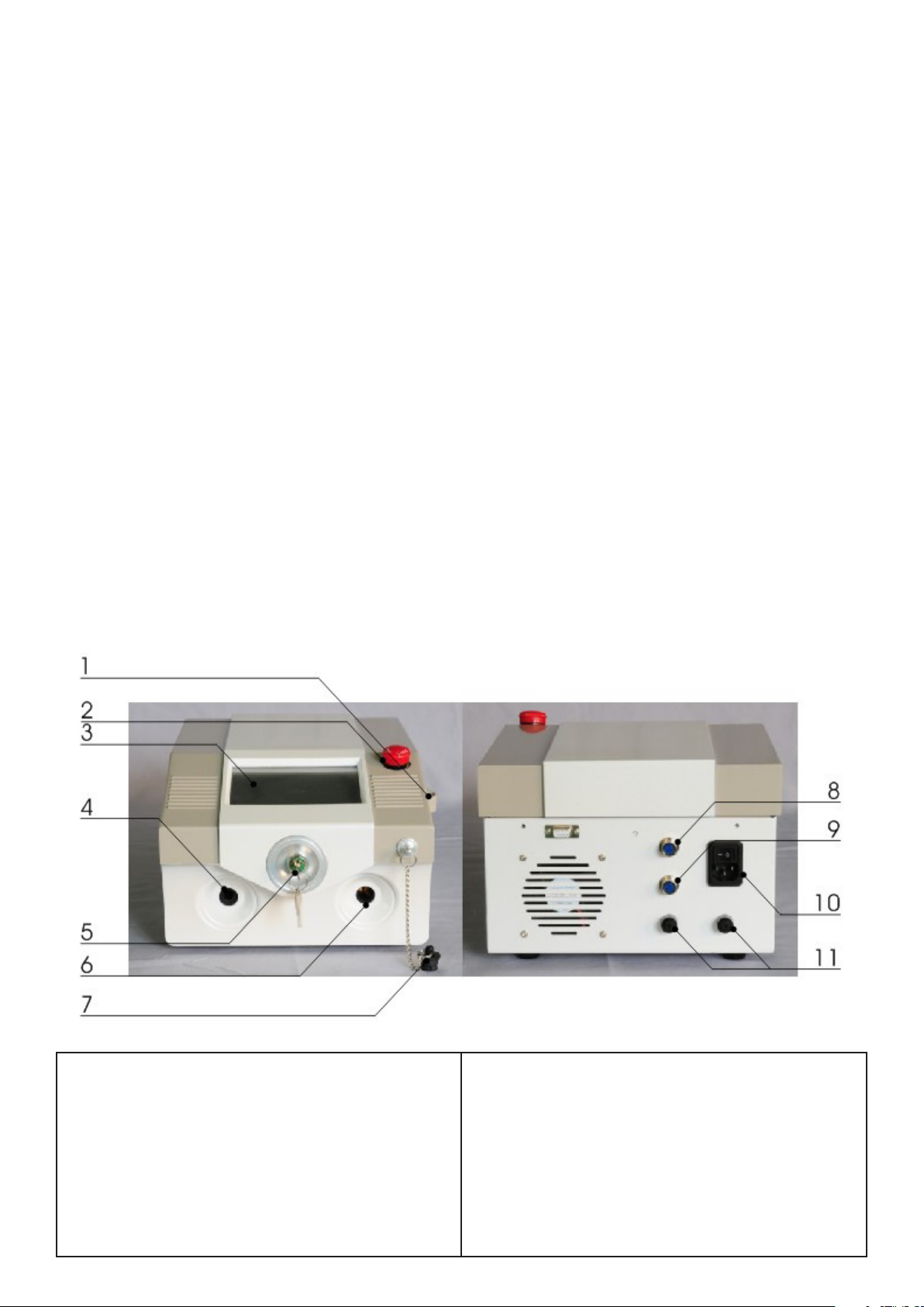
2 Components
1. Fiber pen shelf
8. Foot switch socket
2. Emergency stop switch
3. LCD touch screen
4. Power measure hole
5. Key switch
6. Fiber hole
7. Fiber hole cap
DLC Australia Pty Ltd 6 www.dlc.com.au
9. Controller socket
10. Power socket
11. Fuse holder (5A)
Page 7

PD030 DIODE LASER MANUAL
3. Pre-Startup Preparations
3.1 Unpacking and inspection
After unpacking, please check to ensure that the instrument is not seriously damaged,
circuit lines are well connected and accessories are available (see accessories list)
3.2 Checking power voltage
Ensure that the power voltage complies with the requirement of the instrument. Socket is
in working order.
3.3 Connecting power cable
Plug the two terminals of the power cable into the power input socket and the power
socket. (Make sure the ground socket is in working order.)
3.4 Footswitch Connection
Plug the footswitch cable into the socket on the rear part of the instrument. Push in
alignment of the notch until a tone is heard which means a successful lockup.
DLC Australia Pty Ltd 7 www.dlc.com.au
Page 8

PD030 DIODE LASER MANUAL
4. Operation Instructions
4.1 Power ON
a. Connect footswitch, controller and power cord to the machine.
b. Turn on the power switch at the backside, then wait for 30 seconds.
c. Insert the key into the key switch, turn clockwise to power on. The logo (as shown
in gure 1) will be displayed for 3 seconds, then switches to user interface.
Caution: After turn on the power switch, you should wait for 30 seconds before turn
on the key switch.
Figure 1
User Interface
DLC Australia Pty Ltd 8 www.dlc.com.au
Page 9

PD030 DIODE LASER MANUAL
4. Operation Instructions continued.
4.2 Self-Detecting
a. When the machine is switched on, only wavelength and notice area are activated,
the other functions are locked(shown in gray).
b. Please watch and follow the information shown in the notice area.
1) Connect the ber into the ber hole, the notice area will show “SM905 connected” if
the ber is connected correctly.
2) Please wait for the system to recognize the ber diameter. The optical ber area will
be activated if the ber is recognized.
3) Insert the ber pen into the power detection hole, then the system starts power-on
self-calibration. When self-calibration is nished, all functions will be activated.
c. Take out the ber pen according to the notice.
4.3 Parameter Setting
a. Power setting
Press “Power”, the “Key Parameter” area will be highlighted, press “ ” “ ” to adjust power,
then press “Enter” to conrm the setting.
Key Parameter Area
b. Emitting mode and detail parameters setting
There are two alternative emitting modes: continuous pulse and repeat pulse.
The default mode is continuous. The waveform schematic diagram is shown in “Time
parameter” area. If you want to choose repeat pulse, press “Repeat Pulse” in “Mode” area,
the waveform, idle time, duty time will be shown in “Time parameter” area. Press the
parameter you want to adjust and adjust by press number buttons or “+” “-”. Press “Enter”
to conrm.
Mode Area
DLC Australia Pty Ltd 9 www.dlc.com.au
Page 10
PD030 DIODE LASER MANUAL
4. Operation Instructions continued.
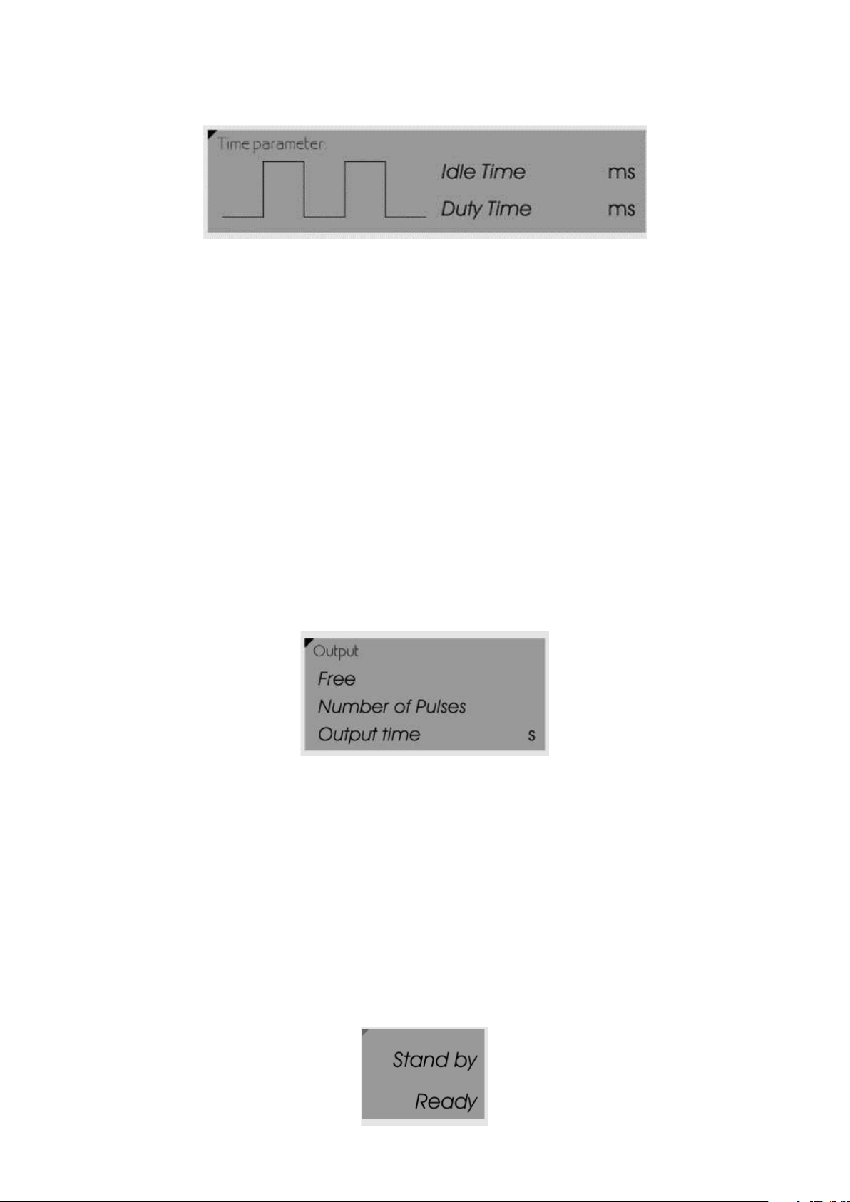
Time Parameter Area
c. Output time setting
There three ways of output:
1. Free output: The laser emits when footswitch is pressed, it is also called real-time
output.
2. Pre-set pulse amount: Input the amount of pulses need to output. When the
footswitch is pressed, the laser emits pulse of the amount you set.
3. Pre-set time: Estimate and then input the treatment time. When the footswitch is
pressed, the laser emits for the time you set.
Caution: Pre-set pulse and Pre-set time are designed for experienced users.
We strongly recommend that new users use free output.
Press the output mode you want and set the value(same as detail parameter setting), then
press “Enter” to conrm.
Output Area
4.4 Change Status and Emit
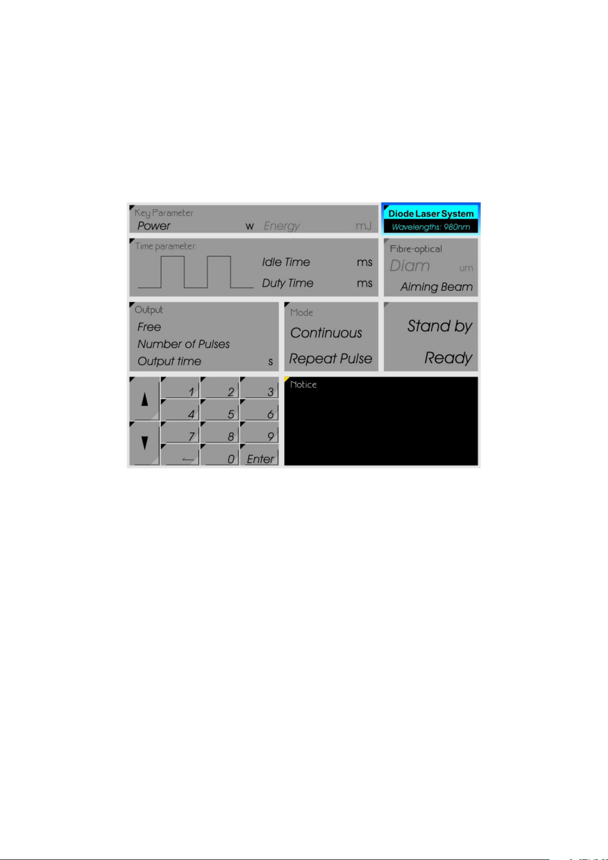
After all parameters are set and conrmed, press “Ready” to switch to ready status, the
parameters will be locked.
Then press the footswitch, laser will emit as you set.
If you want to change parameters, press “Stand by” to switch to stand-by status.
DLC Australia Pty Ltd 10 www.dlc.com.au
Page 11
PD030 DIODE LASER MANUAL
4. Operation Instructions continued.
4.5 Automatic Calibration
When the power is set up, user can calibrate the output power:
1. Set up the power, then insert the ber pen into the power meter hole, the system
would change to auto calibration interface.
2.
3. Press OK to start the calibration.
4. Please operate according to the notice until the calibration is nished, then take out
the ber pen.
Caution: Do not take out the ber pen when calibration is in process.
When calibrating, the areas are locked except the notice area.
DLC Australia Pty Ltd 11 www.dlc.com.au
Page 12
PD030 DIODE LASER MANUAL
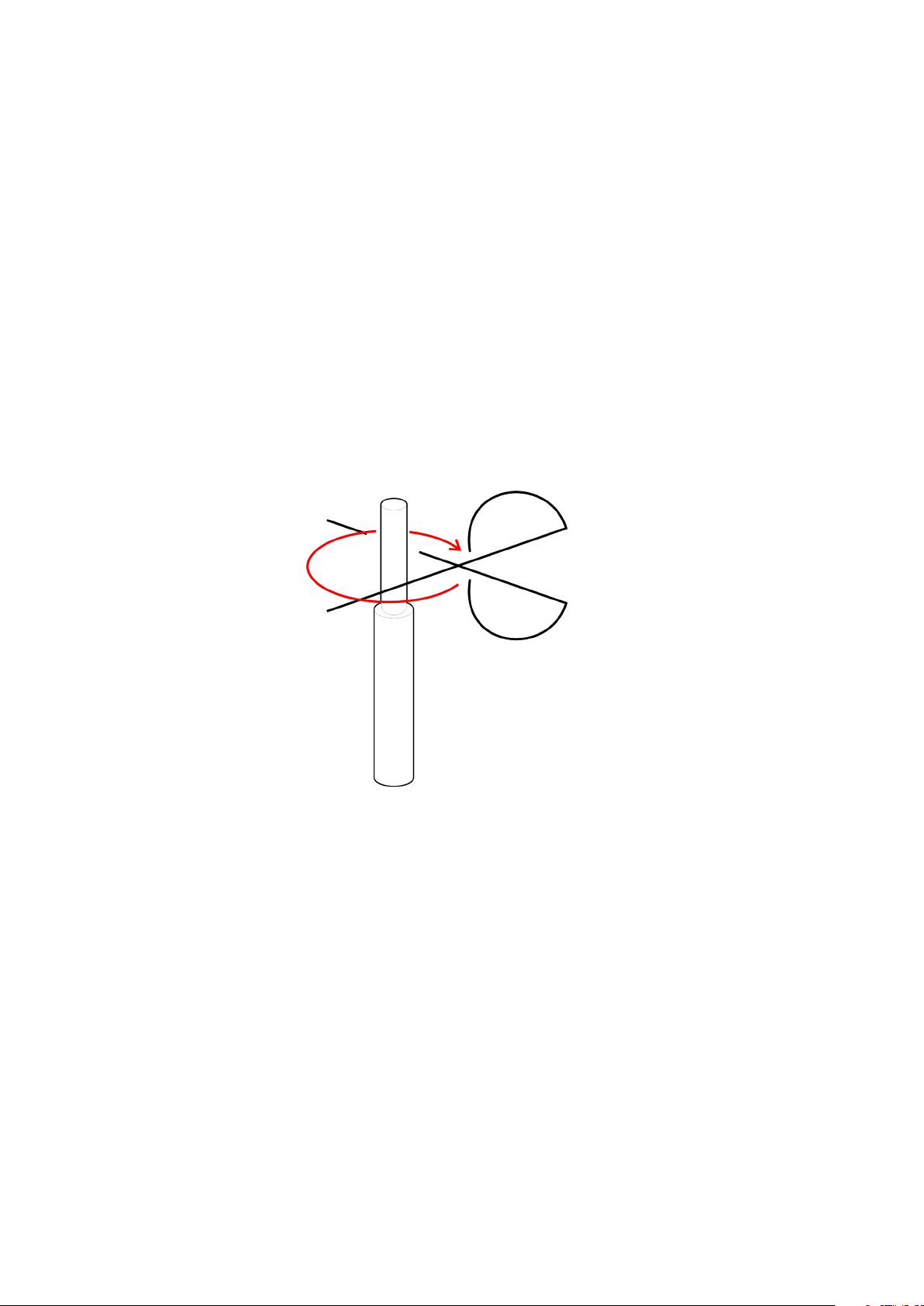
5. Fiber Cutting
Dirty, over-bend, or cut improperly can cause ber get burned, then the ber need to be
re-cut.
Steps of cutting ber:
1. Insert SMA905 into the hole, take the ber out of the ber pen.
2. Rotate the knob of stripper , make the arrow point to the ber diameter, slide the
slider to the desired length (normally 3cm).
3. Insert The ber into the hole, hold strippers tightly on both sides, pull it, remove
two layers of skin, if the skin is not totally stripped , strip again.
4. Open the Fiber scissors and put ber in, gently cut into the blade around the optical
ber, then cut the ber.
5. If the aiming beam displays a complete circle on the paper, then cut success,
otherwise repeat step 4.
6. Insert the ber into ber pen.
6 Protection
6.1 Overheat Protection
To prevent the system become overheated, when the temperature is above 50°C, the
system will stop emitting automatically. Please wait until the machine is cooled down.
DLC Australia Pty Ltd 12 www.dlc.com.au
Page 13

PD030 DIODE LASER MANUAL
7. Precautions
1. Never let the laser beam be directed to human eyes or healthy skin.
2. To prevent human eyes or skin from being hurt by the reection of laser light, never
allow the laser beam, be directed to any smooth reective surface, such as stainless
steel device surface, mirror surface, etc.
3. If 75%, alcohol is used to clean or sterilize relevant part of the instrument, don’t use
the instrument till the alcohol vaporizes. Never operate the instrument in the
presence of ammable anesthetics.
4. The laser beam generated by this instrument is hazardous to eyes in the area within
35m from the instrument (when someone is staring directly at the laser) operators
must use safety eye wear when operating.
5. This instrument generates high voltages inside. No attempt should be made by
non-professional to open the cabinet of the instrument to avoid electric shock risk.
6. If the instrument gives out abnormal smell or sound, stop operation at once. Cut o
the power rst before any inspection.
7. Keep the instrument in an environment with the temperature between 1C~50C and
the relative humidity between 10%~80%.
8. To avoid improper use of the instrument, remove the key from the key switch
and keep it properly when the instrument is not in use. The instrument
generates high voltages within the power supply. Please refer to professional
personnel for maintenance to avoid electric shock.
9. Operation room should be equipped with a dust or fume exhauster, because the
dust arising during operations may be mixed with biological tissue particles.
DLC Australia Pty Ltd 13 www.dlc.com.au
Page 14

PD030 DIODE LASER MANUAL
8. Maintenance
The instrument generates high voltages within power supply. Refer to professional
personnel for maintenance to avoid electric shock.
8.1 Cabinet cleaning
If there is dirt on the cabinet, wipe gently with moistened cotton cloth and some
detergent or toothpaste. Don’t use over-wet cloth in case the water leaks into the inner
part of the instrument, causing short circuit and damage.
8.2 Power calibration
The practical laser output power and the preset panel power must be calibrated each
year with standard laser power meter within validity period by trained of professional
personnel.
8.3 Fuse replacement
Open the fuse holder with a screwdriver and remove the original fuse. Before
replacement, check and ensure the new fuse is identical in type and specication to the
original one (5A) to avoid damage arising from unt fuses.
DLC Australia Pty Ltd 14 www.dlc.com.au
Page 15

PD030 DIODE LASER MANUAL
9. Accessories
Fiber(400um) 1
Fiber pen 1
Power cord 1
Footswitch 1
Controller 1
Interlock key 2
Fiber stripper 1
Fiber scissors 1
10. Technical Specications
Working Modes Continuous, Repeat pulse
Output Power 0~30W adjustable
Laser Type Diode laser
Wavelength 980nm
Duty Time 0.01~1s
Idle Time 0.01~1s
Aiming Beam 635nm diode laser
Delivery System 200um, 400um, 600um, 800um diameter ber
Control System Foot switch, LCD touch screen
Temperature 5~40
Relative Humidity <80%
Power Input AC220V±10%, 50Hz
Weight 10kg
Dimensions 43 × 30 × 20cm
DLC Australia Pty Ltd 15 www.dlc.com.au
Page 16
PD030 DIODE LASER MANUAL
11. Warranty and Service
The instrument is a well designed, user friendly laser surgical system with high quality.
It performs perfectly under normal use and maintenance. Within a year from the date of
purchasing, any damage caused by manufacturing or components defects can enjoy free
repairing service.
Such service is valid only if the instrument is properly used. Any damage cause by
improper use of the instrument, such as using untted power supply and wrong
accessories, operating in a manner other than specied in this operators manual,
damages caused by transportation, accidents unauthorized installation or maintenance,
etc, such free service will be invalid immediately. The free service does not include
accessories transportation free and door-to-door service charge of professional personnel.
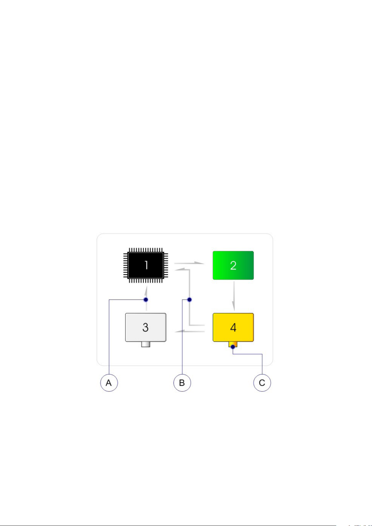
12. Structure
1. CPU
2. Power supply
3. Power meter
4. Diode laser module
A. Real-time power monitor
B. Automatic power calibration
C. Automatic ber identication
DLC Australia Pty Ltd 16 www.dlc.com.au
Page 17
PD030 DIODE LASER MANUAL
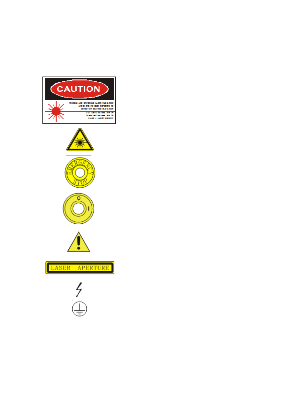
13. Label Explanations
No. Symbol Denition
1 Warning and explanation label
2 Warning label - Hazard symbol
3 Emergency stop switch
4 Position “1” is power “ON” (power:
connection to the mains) Position “0”
is power “OFF” (power disconnection
from the mains)
5 Attention, consult ACCOMPANYING
DOCUMENTS
6 Aperture label
7 HIGH VOLTAGE Dangerous label
8 Protect earth
DLC Australia Pty Ltd 17 www.dlc.com.au
Page 18

Southern Oce: Ph: 03 9360 9700 · Fax: 03 9360 9444 · Toll Free: 1300 785 405 · Email: [email protected]
PO Box 4438, 17-19 Horne Street, Hoppers Crossing, VIC, 3029
Northern Oce: Ph: 07 5428 3666 · Fax: 07 5428 3777 · Toll Free: 1300 785 401 · Email: [email protected]
PO Box 833, Unit 6/1 Lear-Jet Drive, Caboolture, QLD, 4510
www.dlc.com.au · www.dlcimaging.com.au
 Loading...