

Page 1
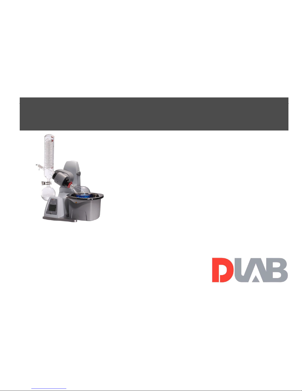
Rotary Evaporator
User Manual
RE100-Pro
LCD Digital Rotary Evaporator
Please read the User Manual carefully before use, and follow all
operating and safety instructions!
Technical specifications and outline are subject to change without prior
notice.
Page 2

Page 3

3
LED Digital 7” Square Hotplate Stirrer
Contents
Preface ................................................................................. 1
Service ................................................................................. 1
Warranty .............................................................................. 1
1. Safety Instructions ....................................................... 2
2. Proper Use ................................................................... 5
3. Inspection .................................................................... 6
3.1 Receiving Inspection ............................................. 6
3.2 Listing of Items ..................................................... 6
4. Control and Display .................................................... 6
4.1 Control elements ................................................... 6
4.2 Display .................................................................. 8
5. Installation and Operation ........................................... 9
5.1 Installation ............................................................. 9
5.2 Operation ............................................................. 12
6. Faults ......................................................................... 13
7. Maintenance and Cleaning ........................................ 14
8. Associated Standards and Regulations ...................... 15
9. Specifications ............................................................ 16
Page 4

Page 5

1
Preface
Welcome to the “Rotary Evaporator User Manual”. Users
should read this Manual carefully, follow the instructions
and procedures, and be aware of all the cautions when using
this instrument.
Service
When help needed, you can always contact the service
department of manufacturer for technical support in the
following ways:
Dragon Laboratory Instruments Limited
No.31, Yu An Road, Zone B of TianZhu Airport Industrial
Park, Shunyi District, Beijing, 101318 P. R. China
Tel: 86-10-85653451/52/53
Fax:86-10-85653383
E-mail: [email protected]
Service Hotline: 400-1100-556
Http://www.dragon-lab.com
Please provide the customer care representative with the
following information:
• Serial number(on the rear panel)
• Certification
• Description of problem (i.e., hardware or software)
• Methods and procedures adopted to resolve the problems
• Your contact information
Warranty
This instrument is warranted to be free from defects in
materials and workmanship under normal use and service,
for a period of 24 months from the date of invoice. The
warranty is extended only to the original purchaser. It shall
not apply to any product or parts which have been damaged
on account of improper installation, improper connections,
misuse, accident or abnormal conditions of operation.
For claims under the warranty please contact your local
supplier. You may also send the instrument directly to
manufacturer, enclosing the invoice copy and by giving
reasons for the claim.
Page 6

2
1. Safety Instructions
• Read the operating instructions in full before starting
up and follow the safety instructions.
• Keep the operating instructions in a place where they
can be accessed by everyone.
• Ensure that only trained staff work with the appliance.
• Follow the safety instructions, guidelines, occupational
health and safety and accident prevention regulations.
When working under a vacuum in particular!
• Wear your personal protective equipment in
accordance with the hazard category of the medium to
be processed. Otherwise there is a risk of:
- splashing liquids,
- body parts, hair, clothing and jewellery getting
caught,
- injury as a result of glass breakage.
• CAUTION! Inhalation of or contact with media such
as poisonous liquids, gases, spray mist, vapours, dusts
or biological and microbiological materials can be
hazardous to user.
• Set up the device in a spacious area on an even, stable,
clean, non-slip, dry and fireproof surface.
• Ensure that there is sufficient space above the device
as the glass assembly may exceed the height of the
device.
• Prior to each use, always check the device, accessories
and especially the glass parts for damage. Do not use
damaged components.
• Ensure that the glass assembly is tension-free! Danger
of cracking as a result of:
- stress due to incorrect assembly,
- external mechanical hazards,
- local temperature peaks.
• Ensure that the stand does not start to move due to
vibrations respectively unbelance.
• Beware of hazards due to:
- flammable materials,
- combustible media with a low boiling temperature,
- glass breakage.
• CAUTION! Only process and heat up media that has a
flash point higher than the adjusted safe temperature
limit of the heating bath that has been set.
• The safe temperature limit of the heating bath must
always be set to at least 25 °C lower than the fire point
of the media used.
Page 7

3
• Do not operate the appliance in explosive atmospheres,
with hazardous substances or under water.
• Only process media that will not react dangerously to
the extra energy produced through processing. This
also applies to any extra energy produced in other
ways, e.g. through light irradiation.
• Tasks with the device must only be performed when
operation is monitored.
• Operation with excess pressure is not permitted (for
cooling water pressure see "Technical Data").
• Do not cover the ventilation slots of the device in
order to ensure adequate cooling of the drive.
• There may be electrostatic discharges between the
medium and the drive which could pose a direct
danger.
• The appliance is not suitable for manual operation.
• Safe operation is only guaranteed with the accessories
described in the ”Accessories” chapter.
• Refer to the operating instructions for the accessories,
e.g. vacuum pump.
• Only use the device under an all side-closed exhaust,
or a compa rable protective device.
• Adapt the quantity and the type of distilland to the size
of the distillation equipment. The cooler must work
properly. Monitor the coolant flow rate at the cooler
outlet.
• The glass equipment must always be ventilated when
working under normal pressure (e.g. open outlet at
cooler) in order to prevent a pressure build-up.
• Please note that dangerous concentrations of gases,
vapours or particulate matter can escape through the
outlet at the cooler. Take appropriate action to avoid
this risk, for example, downstream cold traps, gas
wash bottles or an effective extraction system.
• Evacuated glass vessels must not be heated on one side;
the evaporating flask must rotate during the heating
phase.
• The glassware is designed for operation under a
vacuum of up to 10 mbar. The equipment must be
evacuated prior to heating (see chapter
“Commissioning”). The equipment must only be aired
again after cooling. When carrying out vacuum
distillation, uncondensed vapours must be condensed
out or safely dissipated. If there is a risk that the
distillation residue could disintegrate in the presence
of oxygen, only inert gas must be admitted for stress
Page 8

4
relief.
• CAUTION! Avoid peroxide formation. Organic
peroxides can accumulate in distillation and exhaust
residues and explode while decomposing!
• Keep liquids that tend to form organic peroxides away
from light, in particular from UV rays and check them
prior to distillation and exhaust for the presence of
peroxides. Any existing peroxides must be eliminated.
Many organic compounds are prone to the formation
of peroxides e.g. dekalin, diethyl ether, dioxane,
tetrahydrofuran, as well as unsaturated hydrocarbons,
such as tetralin, diene, cumene and aldehydes, ketones
and solutions of these substances.
• DANGER OF BURNING! The heating bath,
tempering medium, evaporator piston and glass
assembly can become hot during operation and remain
so for a long time afterwards! Let the components cool
off before continuing work with the device.
• ATTENTION! Avoid delayed boiling! Never heat the
evaporating flask in the heating bath without switching
on the rotary drive!Sudden foaming or exhaust gases
indicate that flask content is beginning to decompose.
Switch off heating immediately. Use the lifting
mechanism to lift the evaporator piston out of the
heating bath. Evacuate the danger zone and warn those
in the surrounding area!
• When the device is switched off or the power supply
disconnected, the internal safety lift removes the
evaporator piston from the heating bath.
• CAUTION! Never operate the device when the
evaporator piston is rotating and the lift is raised.
Always lower the evaporator piston into the heating
bath first before starting the rotation drive. Otherwise
hot tempering medium may be sprayed out!
• Set the speed of the drive so no tempering medium is
sprayed out as a result of the evaporator piston rotating
in the heating bath. If necessary reduce the speed.
• Do not touch rotating parts during operation.
• Imbalance may result in uncontrolled resonance
behaviour of the device or assembly. Glass apparatus
may be damaged or destroyed. In the event of
unbalance or unusual noises, switch off the appliance
immediately or reduce the speed.
• The appliance does not start up again automatically
following a cut in the power supply.
• The device is only disconnected from the power
Page 9

5
supply network if the device power switch is off or the
plug is pulled out.
• The socket for the mains cord must be easily
accessible.
• The voltage stated on the type plate must correspond
to the mains voltage.
• Socket must be earthed (protective ground contact).
• Removable parts must be refitted to the appliance to
prevent the infiltration of foreign objects, liquids etc.
• Protect the appliance and accessories from bumps and
impacts.
• The appliance may only be opened by experts.
2. Proper Use
The instrument is designed for distilling in schools,
laboratories or factories. Together with the accessories
recommended by manufacturer, the device is suitable for:
- quick and gentle distillation of liquids
- evaporation of solutions and suspensions
- crystallisation, synthesis or cleaning of fine chemicals
- drying of powder and granulate material
- recycling of solvents
This device is not suitable for using in residential areas or
other constraints mentioned in Chapter 1.
Page 10
6
3. Inspection
3.1 Receiving Inspection
Unpack the equipment carefully and check for any damages
which may have arisen during transport. Please contact
manufacturer/supplier for technical support.
Note:
1. If there is any apparent damage to the system,
please do not plug it into the power line.
2. Loosen transportation lock before Power ON.
3.2 Listing of Items
The package includes the following items:
Items
Qty
Main unit
1
Heating bath
1
Power cable
1
Glassware vertical
1
User Manual
1
Table 1
4. Control and Display
4.1 Control elements
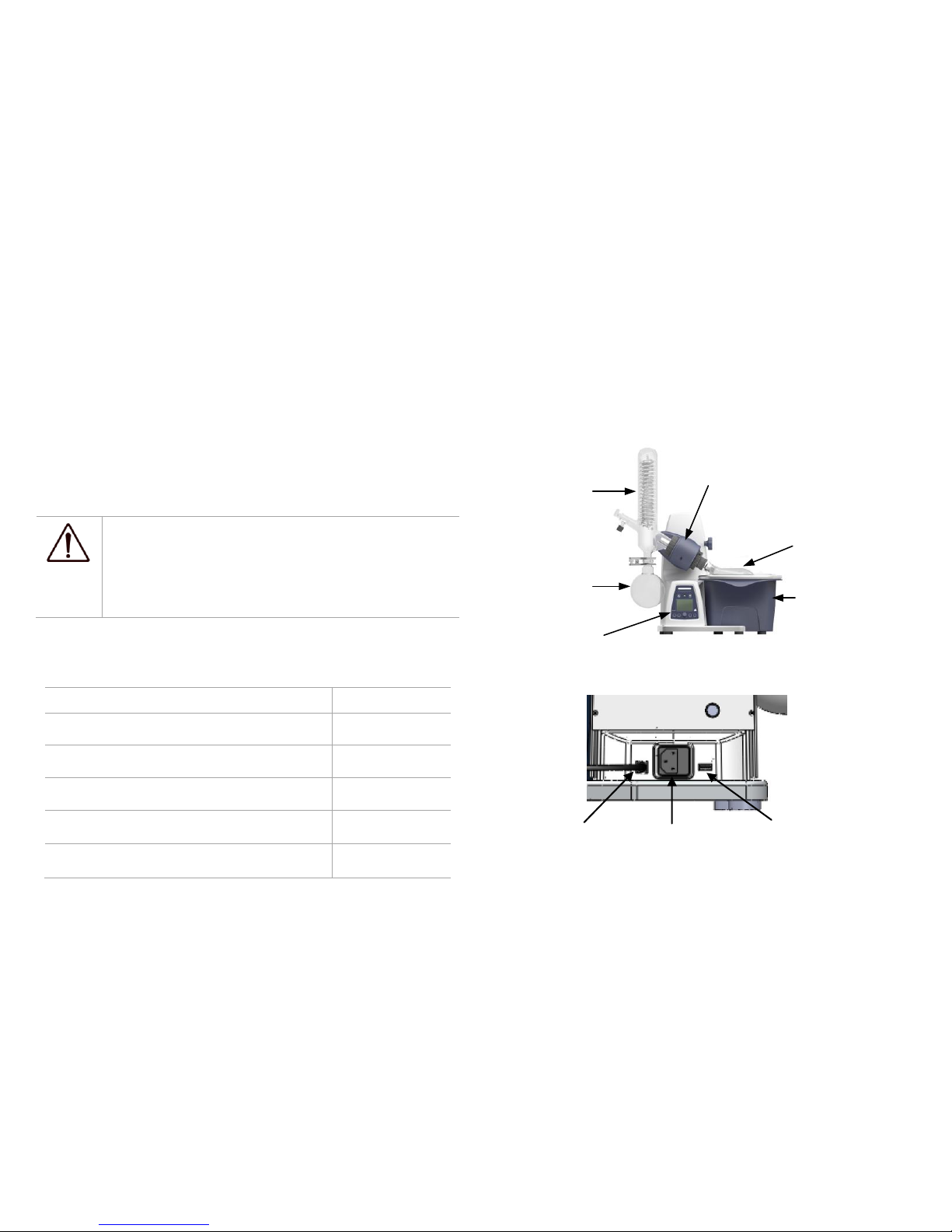
Heating bath
Evaporating flask
Motor
Condenser
Receiving flask
Operation panel
Figure 1
Figure 2
USB
Power supply
Heating bath
connector
Page 11
7
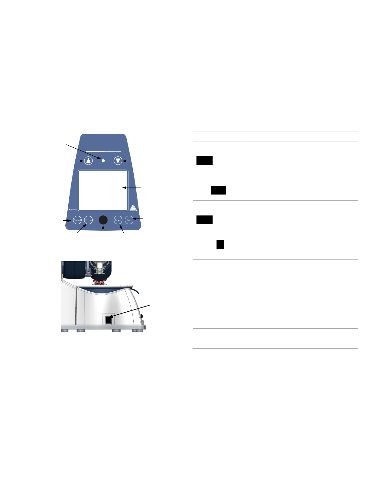
Lift-down key
Int key
Lift-up key
Timer keyControl knob
Temperature key
Speed key
LED power
LCD display
Figure 3
Figure 4
Items
Descriptions
Speed key
Speed
Push the key and then rotate control knob
to set the rated speed in the range from 20
to 280.
Temperature
key Temp
Push the key and then rotate control knob
to set the rated temperature in the range
from room temperature to 180°C .
Timer key
Timer
Push the key and then rotate control knob
to set the rated time in the range from 1
to 999min.
Int key Int
Push the key and then rotate control knob
to set the interval for right-left running in
the range from 1 to 999s.
Control knob
Clockwise rotate to increase program
values. Rotate anti-clockwise to decrease
program values.
Press the knob, switch ON/OFF the unit.
Lift-up key
Press the key, the lift goes up. Release the
key the lift stops and remains in that
position.
Lift-down key
Press the key, the lift goes down. Release
the key the lift stops and remains in that
Power switch
Page 12
8
position.
LCD display
LCD displays the real working state.
LED power
Power ON, LED power flash. When the
unit running, LED power is lit.
Power switch
Power ON or OFF.
Table 2
4.2 Display
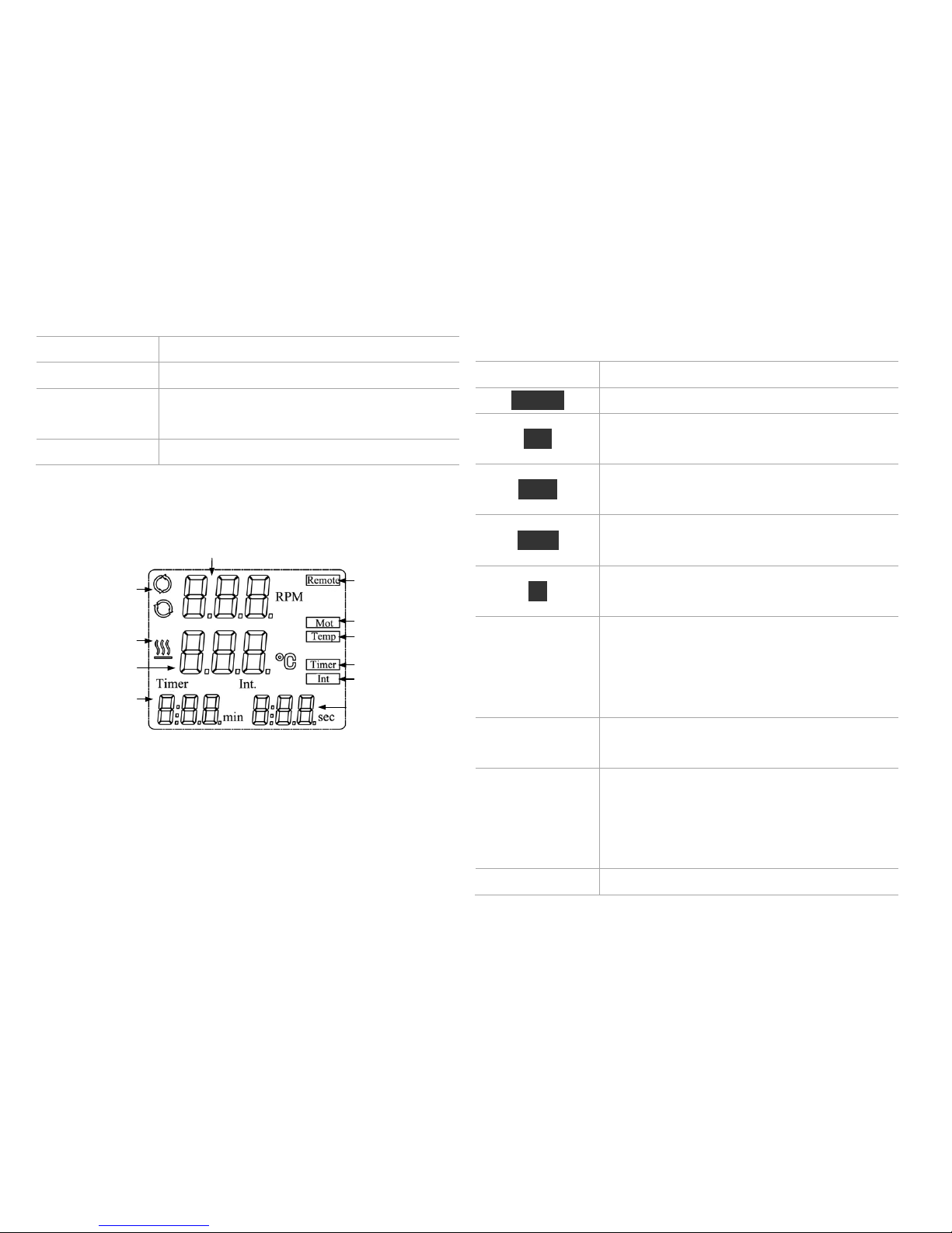
Speed display area
Timer display
area
Interval display
area
Remote control
Rotate
Temperature
Timer
Interval
Temperature
symbol
Speed symbol
Temperature
display area
Figure 5
Display
Descriptions
Remote
Display in case of remote control.
Mot
Display when the rotating function is
switched ON.
Temp
Display when the heating function is
switched ON.
Timer
Display when timer function is switched
ON.
Int
Display when “Int” function is switched
ON.
Speed display
area
When setting speed, displaying the
setting value and flashed. The setting
value does not flash until real speed
reaches the set point.
Speed symbol
Display when the rotating function is
switched ON.
Temperature
display area
When setting temperature, displaying the
setting value. When the heating function
is switched ON, displaying the real
value.
Temperature
Display when the heating function is
Page 13
9
symbol
switched ON.
Timer display
area
When setting timer, displaying the rated
time. When the timer function is
switched ON, displaying remaining time.
Interval display
area
Displaying the “Int” target value.
Table 3
5. Installation and Operation
5.1 Installation
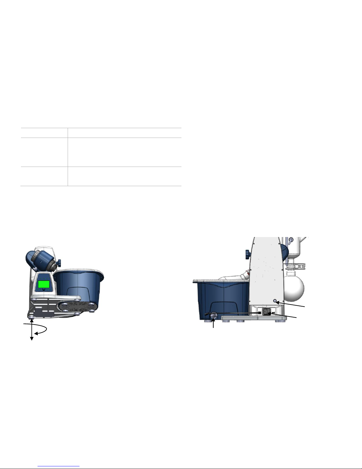
• Adjustable base (Figure 6).
Figure 6
CAUTION! Loosen transportation lock (Figure 7).
• Hold the lift with your hand on the height position and
remove the thumb screw on the back of the appliance
(a).
• Once the transportation lock has been removed, the lift
moves slowly to its upper end position. The distance is
150mm.
• Connect the device to the power supply using power
cable (b).
• Connect the heating bath to the device (c).
Figure 7
a b c
Page 14
10
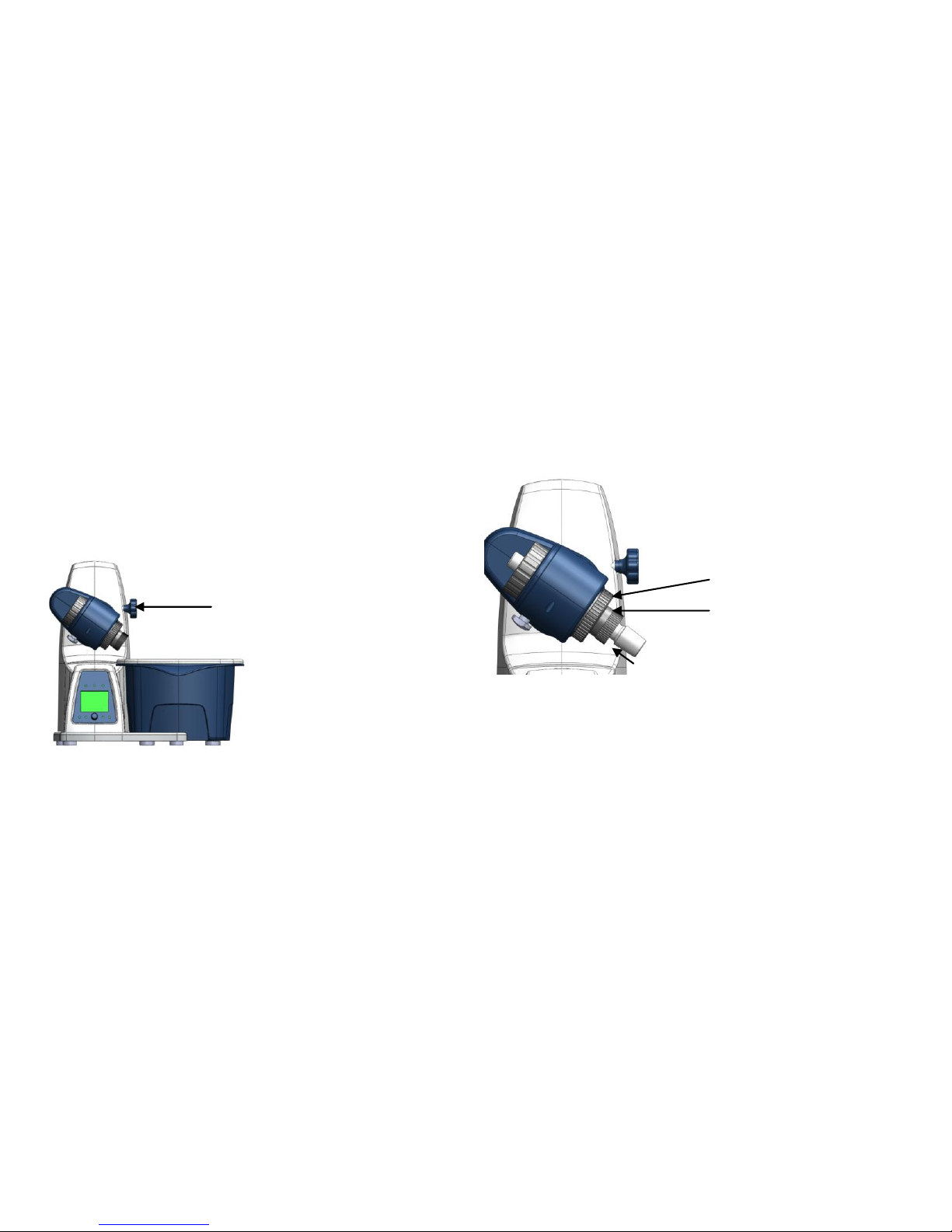
• Remove the clamping device for the angle setting of
the rotation drive on the right side of the lift by
rotating the knurled screw (d) counter clockwise.
• Set the drive at an angle of approx.30° (Figure 8)
• Then secure the rotation drive from being accidentally
turned by tightening the knurled screw in a clockwise
direction.
Figure 8
• Open the locking device on the drive head by turning
it 60° counter clockwise (e), (Figure 9).
• Feed the steam pipe in until it stops.
• Then lock the locking device by turning it clockwise
by 60°.
• The plastic screw nut (f) helps loosen tight-fitting
piston ground-in connections (Figure 9).
- Hold the tight-fitting evaporator piston and
counter clockwise (e), and then turn the plastic
screw nut (f) until the evaporator piston neck.
Figure 9
Note: Prior to commissioning, hand-tighten the plastic
screw nut (f) left-aligned.
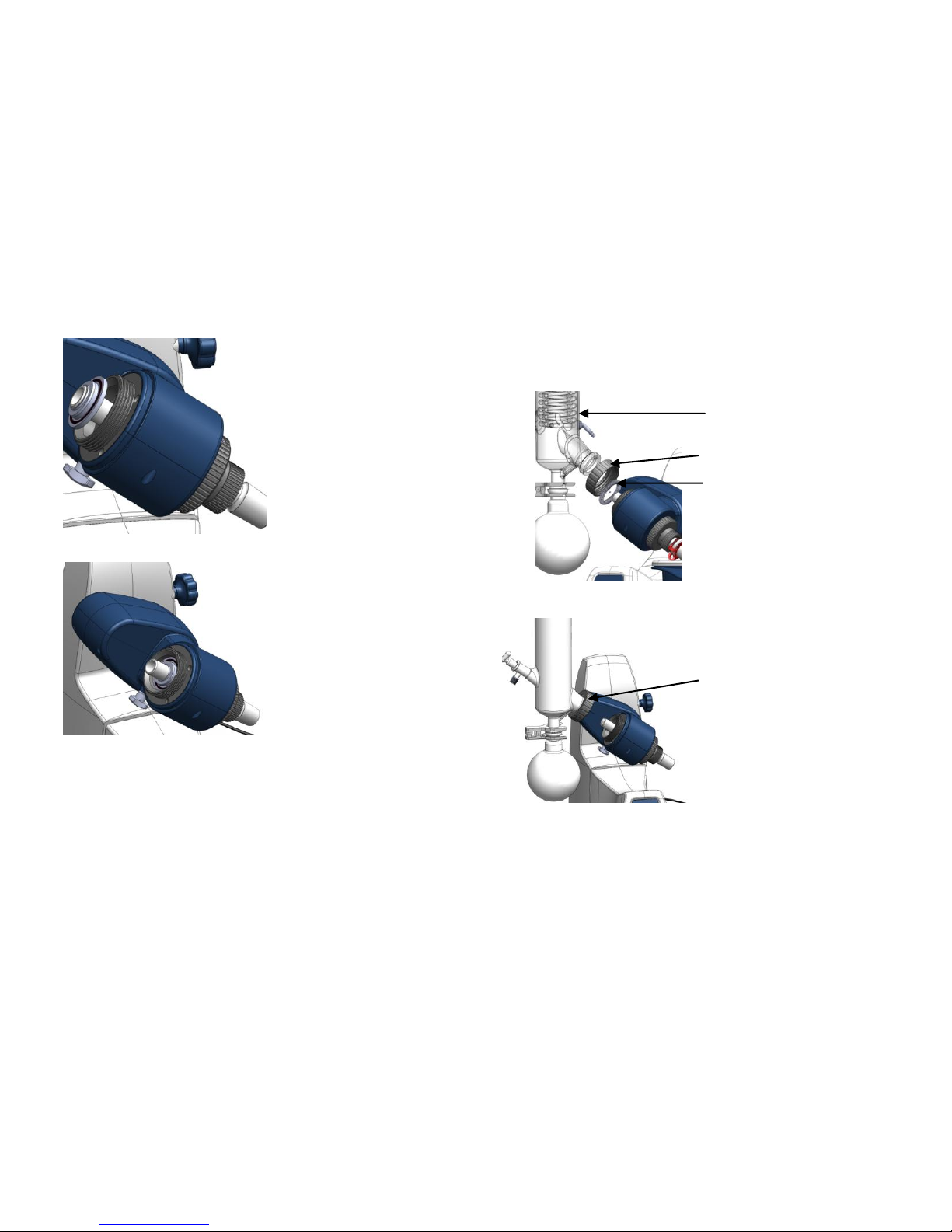
• Installing condenser seal (Figure 10 and Figure 11).
d
f
e
Page 15
11
Figure 10
Figure 11
• Installing condenser (g) (Figure 12 and Figure 13).
- Load the cap nut (h) and locking spring (i) to
condenser in turn.
- Tighten the cap nut hand-screwed (h). Start the
device at 200 rpm for 2 min. Then tighten the cap
nut firmly.
Figure 12
Figure 13
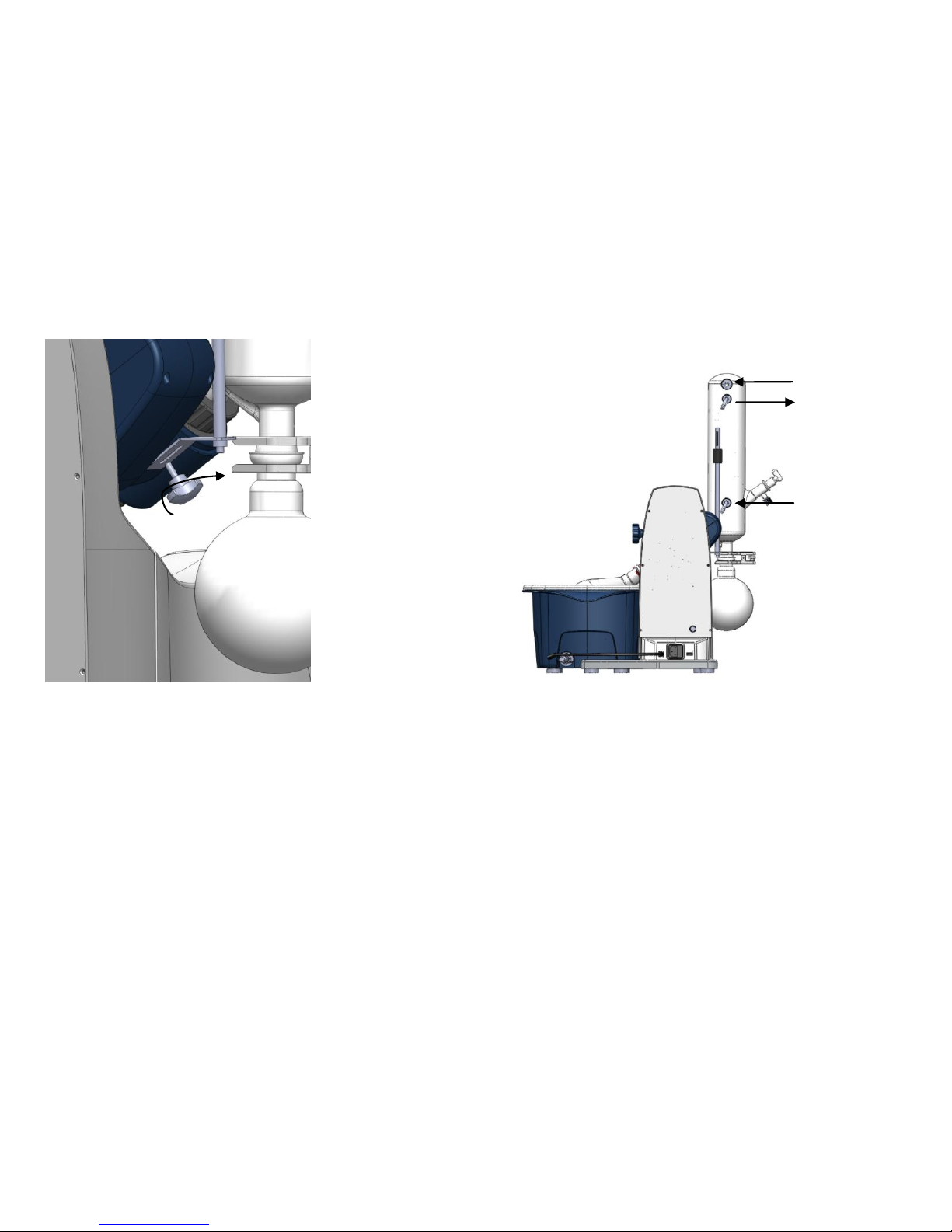
• Installing the vertical glassware condenser locking
device (Figure 14). Use the transportation screw on the
back of the appliance (a)
g
h h i
Page 16
12
Figure 14
• Connecting tubes (Figure 15).
Figure 15
5.2 Operation
• Make sure the required operating voltage and power
supply voltage match.
• Ensure the socket must be properly grounded.
• Plug in the power cable,ensure the power is on and
begin initializing.
• Press Lift-up/Lift-down key, the lift goes up/down.
Cooling water
Cooling water
Vacuum tube
Page 17

13
Release Lift-up/Lift-down key, the lift stops.
• Push the speed key and then rotate control knob to set
the rated speed.
• Push the temperature key and then rotate control knob
to set the rated temperature.
• Push the timer key and then rotate control knob to set
the rated time.
Deactivate the timer by setting the target value to “0”.
• Press the Int key and then rotate control knob to set the
rated interval value.
Deactivate the interval by setting the target value to
“0”.
• Press the control knob, switch ON.
If these operations above are normal, the device is ready to
operate. If not, the device may be damaged during
transportation, please contact manufacturer/supplier for
technical support.
Warning !
Forbid to transfer the flask when the instrument
working.
6. Faults
• Instruments can’t be power ON
- Check whether the power line is unplugged
- Check whether the fuse is broken or loose
• Fault in power on self test
- Switch OFF the unit, then switch ON and reset
the instruments to factory default setting.
• ERR 003, lift operation timeout
- Load overweight
• ERR 005, lift can’t work
- Check whether the transportation lock is loosen
- Load overweight
If these faults are not resolved, please contact
manufacturer/supplier.
Page 18

14
7. Maintenance and Cleaning
• Proper maintenance can keep instruments working
properly and lengthen its lifetime.
• Do not spray cleanser into the instrument when
cleaning.
• Unplug the power line when cleaning.
• Only use recommended cleansers:
Dyes
Isopropyl alcohol
Construction materials
Water containing tenside
/ Isopropyl alcohol
Cosmetics
Water containing tenside
/ Isopropyl alcohol
Foodstuffs
Water containing tenside
Fuels
Water containing tenside
• Before using other method for cleaning or
decontamination, the user must ascertain with the
manufacturer that this method will not harm the
instrument. Wear the proper protective gloves during
cleaning of the instrument.
Note:
• Electronic device can not clean with
cleanser.
• If you require maintenance service, must be
cleaned the instrument in advance to avoid
pollution of hazardous substances, and to
send back into original packing.
• If the instrument will not use for a long time,
please switch off and place in a dry, clean,
room temperature and stable location.
Page 19

15
8. Associated Standards and
Regulations
Construction in accordance with the following safety
standards:
EN 61010-1
UL 3101-1
CAN/CSA C22.2(1010-1)
EN 61010-2-10
Construction in accordance with the following EMC
standards:
EN 61326-1
Associated EU guidelines:
EMC-guidelines: 89/336/EWG
Instrument guidelines: 73/023/EWG
Changes or modifications not expressly approved by the
party responsible for compliance could void the user's
authority to operate the equipment.
NOTE: This equipment has been tested and found to
comply with the limits for a Class A digital device,
pursuant to Part 15 of the FCC Rules. These limits are
designed to provide reasonable protection against harmful
interference when the equipment is operated in a
commercial environment. This equipment generates, uses,
and can radiate radio frequency energy and, if not installed
and used in accordance with the instruction manual, may
cause harmful interference to radio communications.
Operation of this equipment in a residential area is likely to
cause harmful interference in which case the user will be
required to correct the interference at his own expense.
Page 20

16
9. Specifications
Items
Specifications
Voltage [VAC]
100-240
Frequency [Hz]
50/60
Power [W]
1400
Motor
External rotor brushless
motor
Speed Range [rpm]
20-280
Speed Display
LCD
Reversible Direction of
Rotation
Yes
Temperature Range [°C]
RT -180
Heat Control Accuracy [°C]
±1
Temperature Display
LCD
Heat Output [W]
1300
Lift
Motor
Stroke [mm]
150
Timer [min]
1-999
Overall Dimensions
[D×W×H ,mm]
465×457×583
Weight [kg]
15
Permissible Ambient
Temperature [°C]
5 - 40
Permissible Relative Humidity
80%
Protection Class acc. To DIN
EN60529
IP20
USB
Yes
Table 4
Page 21

Page 22

2311 E. Locust Court, Ontario, CA 91761 United States.
Office: +1-747-230-5179
Fax: +1-909-230-5275
Sales contact: [email protected]
Service contact: [email protected]
www.dlabsci.com
DLAB Scientific Instrument Inc.
 Loading...