

DLA 64cc Twin-Boxer, 64-I2 In-Line, 58cc, 32cc, 116cc Twin-Boxer Operating Instructions Manual
...
GS R/C
DLA ENGINE OPERATING-INSTRUCTION
MANUAL
DLA 2-CYCLE GAS ENGINES FOR MODEL AIRCRAFT
This Manual presents the necessary information for the operation of all DLA 2-cycle gasoline,
Model Airplane Engines. DLA 32, 58, 64, 64-I2, 116cc, 116cc-I2 and 128cc QUAD
DLA 32cc DLA 58cc DLA 64cc Twin-Boxer
……………….
DLA 64-I2 In-Line DLA 116cc Twin-Boxer DLA 116cc-I2 In-line
DLA 128cc QUAD-Boxer DLA 18cc Twin Boxer DLA 232cc QUAD Boxer
Manufactured by: FeiaoModel, www.dlaengine.com; USA Distributor: GOLDEN SKIES R/C
Aircraft, Inc. www.goldenskiesrc.com 949-378-5998
06/29/2016 Copyrighted Material
Owner’s Manual All Rights Reserved 03180-10000
Page - 1 DLA 32, 58, 64, 64-I2, 116, 116-I2 & 128cc, 180c, 232cc Rev. A.05.11

GS R/C
DLA ENGINE OPERATING-INSTRUCTION
MANUAL
TABLE OF CONTENTS
Welcome ……………………………….…………………………………….…………….. 3
Legal Disclaimer / Assumption of Liability …………………………………... 4-6
Accessories and Support Items ……………………………………………………. 7-12
About DLA Engines ……………………………………………………………………. 13
Technical Specifications: 32cc, 58cc, 64cc, 116cc, 116-I2, 128cc ………. 13-14
What is in the box ………………………………………………………………………. 14
o Damaged or Missing Parts ………………………….…………………………….. 14-15
Intended Engine Use ………………………………………………………………….. 16
Safety Instructions ……………………………………………………………………… 16-18
Installation in Model Aircraft ………………………………………………………. 18-24
o Mounting Engine to Aircraft Firewall …………………………………………. 18
o Spark Plug ……………………………………………………………………………….. 20
o Muffler ………………………………………………………………………………….…. 20
o Installing Fuel (Gas) Tank, Plumbing …………………………………………. 20
o Ignition Installation and Wiring ………………………………………….….….. 20-25
o Engine CDI/Sensor Timing …………………………………………….… 25
o Cowl Ducting and Air Flow ………………………………………………….…….. 25
o Temperature Limits …………………………………………………………. 26
Fuel – GAS ……………………………………………………………………………….... 26
o Type of Gas and Oils ……………………………………………………………….… 26
o Tank Installation …………………………………………………………………….… 26
o Filters …………………………………………………………………………………….… 26
o Fuel Point™ ……………………………………………………………………………... 28
116-I2 , 128cc Sensor Connection / Identification ……………………… 24
Propeller Selection …………………………………………………………………….… 24-28
o Drilling the Propeller Bolt Holes ………………………………………... 29
Spinners and Drilling the Back Plate …………………………………………….. 30
Engine Starting ….................................................................................... 30
o Break-in …………………………………………………………………………………… 30
o Normal Flight Operation ……………………………………………………………. 31
Engine Maintenance ……………………………………………………………………. 32-36
o Parts Diagram …………………………………………………………………………… 32-37
o Parts List ………………………………………………………………………………….. 33-34
Carburetor Tuning and Care ………………………………………………………… 39-39
Trouble Shooting ………………………………………………………………………… 40-41
Warranty ……………………………………………………………………………………. 43-44
o Warranty Extension …………………………………………………………………… 43
Dimensioned Engine Drawings and Parts Diagram ...……………………….. 32-36
Dimensioned Mounting Guide (Table 1) ………………………..………………. 45
Published Specifications (Table 2) .................…………………………………… 46-50
Torques: Engine Bolts ………………………………………………………………….. 50
Oil:Gas Mixture Table ………………………………………………………………….. 51
06/29/2016 Copyrighted Material
Owner’s Manual All Rights Reserved 03180-10000
Page - 2 DLA 32, 58, 64, 64-I2, 116, 116-I2 & 128cc, 180c, 232cc Rev. A.05.11

GS R/C
DLA ENGINE OPERATING-INSTRUCTION
MANUAL
WELCOME:
Thank you for purchasing the DLA Engine through the GOLDEN SKIES R/C Aircraft, Inc. (GS
R/C) Distributorship and Distribution Channel. Welcome to the world of DLA performance and
GOLDEN SKIES R/C AIRCRAFT, INC. USA service and support. We trust you will find DLA
Engines and GOLDEN SKIES R/C AIRCRAFT, INC. form the perfect combination for excellent
flight performance and service. It is mandatory that you, the consumer read this engine operation
manual entirely and thoroughly, strictly follow all processes and procedures, most specifically the
Safety Instructions and Disclaimer and Legal Liability Sections. If the consumer has any
questions regarding this manual, DLA Engines and the operation thereof, please contact GOLDEN
SKIES R/C AIRCRAFT, INC. at 949-378-5998 for assistance. When the consumer breaks
the seal on the DLA Operations Instructions Manual Envelope, the consumer
acknowledges and agrees with, and to, the Terms and Conditions (T&Cs) listed in
the Safety and Legal Disclaimer Sections of this manual. If the consumer does not
acknowledge and agree to the Terms and Conditions (LEGAL DISCLAIMER / ASSUMPTION
OF LIABILITY: Assumption of Risk Legal agreement only), return the engine to the place
of purchase for a refund. Limitations on the return and refund may apply; see the Warranty
Section of the manual for limitations. Retailer Terms may differ with each individual Retailer.
The consumer must register the DLA Engine warranty within seven (7) days of the original
purchase date, with Golden Skies R/C Aircraft, Inc. for the warranty to apply.
If the envelope seal is already broken, such as might be experienced at a retail store, the original
purchaser must assume the responsibility of acknowledging and agreeing to the Terms and
Conditions of as noted above.
06/29/2016 Copyrighted Material
Owner’s Manual All Rights Reserved 03180-10000
Page - 3 DLA 32, 58, 64, 64-I2, 116, 116-I2 & 128cc, 180c, 232cc Rev. A.05.11

GS R/C
DLA ENGINE OPERATING-INSTRUCTION
MANUAL
LEGAL DISCLAIMER / ASSUMPTION OF LIABILITY:
Assumption of Risk Legal agreement only
Warning
The Radio Controlled (R/C), Aircraft propelled by DLA Engines are NOT Toys and are
potentially dangerous to property and individuals within numerous miles of your flying area. It is
capable of causing substantial property damage, serious bodily harm, and possibly death if it
strikes personal property or an individual.
Consumer’s Responsibility
1) Assembly and Use
IT IS YOUR RESPONSIBILITY AND YOURS ALONE to assemble the Aircraft and DLA Engine
correctly and to properly install all additional components, both included in the DLA Engine kit
and/or acquired by the purchaser of this DLA Engine; to preflight test the model; to follow all
Safety Instructions listed herein, and to fly ONLY in an American Model Aeronautics Association
(AMA) approved flying site with the supervision and/or assistance of a fully qualified flying site
instructor. The pilot of any aircraft must comply with all of the AMA’s Safety Codes. The
employment of common sense for safety of yourself and others is otherwise mandatory. The
aircraft has a radio range of 500 (or less) feet and the pilot is directed not to exceed this distance
when flying the aircraft and DLA Engine. In the event the range is exceeded, the pilot will lose
control of the aircraft which could cause injury and damages to objects which the aircraft may
come into contact with upon an uncontrolled landing. Do not attempt to fly any model aircraft if
you have not been qualified as a solo pilot by the instructor at the AMA approved flying site. It is
recommended that on any first flight of a new R/C aircraft and DLA Engine that you attain the
assistance or instruction of a highly experienced R/C pilot to verify the aircraft and DLA Engine
installation-construction from a safety and flight perspective. If you are just starting to fly R/C
Model Aircraft of any type, consult your local Hobby Shop or write to the Academy of model
Aeronautics to find an experienced instructor in your area.
2) Assumption of the Risk
Participation in the operation of remote controlled aircraft is voluntary. I, the purchaser,
understand that the operation of remote controlled aircraft is a dangerous sport which can result
in bodily injury, death, and/or damage to property for many reasons, including but not limited to
airplane accidents involving third parties known and unknown to the user; equipment failure,
malfunction, or misuse; weather conditions such as storms and lightning; the training, acts,
omissions, recommendations or advice given by your local Hobby Shop or the Academy of model
Aeronautics concerning the operation of remote controlled aircraft and related activities such as
transportation to and from the site; and first-aid, emergency treatment or other services rendered
to me as a user or others. I understand and acknowledge that the above list of reasons is not
complete or exhaustive. I accept and hereby assume all risks of injury, death, illness or disease, or
06/29/2016 Copyrighted Material
Owner’s Manual All Rights Reserved 03180-10000
Page - 4 DLA 32, 58, 64, 64-I2, 116, 116-I2 & 128cc, 180c, 232cc Rev. A.05.11

GS R/C
DLA ENGINE OPERATING-INSTRUCTION
MANUAL
other damage to myself, to others, or to my property which arise from participation in the
referenced activities.
3) Release
I hereby voluntarily release, and forever discharge GOLDEN SKIES R/C AIRCRAFT, INC., a
California Corporation, on its behalf and on the behalf of its successors and assigns, and each of
them (“Golden Skies”) and its subcontractors, and all other persons or entities associated with it,
including other participants, (hereafter collectively the released parties) from all liability, claims,
demands, actions or causes of action for bodily injury, death, illness, disease or damage to myself,
to any participating minor child of mine, or to my property which are related to, arise out of, or
are in any way connected with participation in the above referenced activities, including but not
limited to those arising from any negligent or reckless acts or omissions or breach of contract of
the released parties, or hidden defects in the equipment used. This release is intended to be as
broad and inclusive as is permitted by California law, and shall be construed and interpreted
under California law. If any portion, clause or sub clause is held invalid, I agree that the balance
shall continue in full force and effect.
4) Maintain Proper Insurance Coverage
It is also mandatory that all R/C airplane pilots obtain adequate insurance through their own
homeowner policy or a separate policy to cover liability in the event of property damage or injury
to individuals or personal property. Additionally, all R/C airplane pilots must join the AMA to
become secondarily insured.
Academy of Model Aeronautics http://www.modelaircraft.org ….
Academy of Model Aeronautics
5151 East Memorial Drive
Muncie, Indiana 47302-9252
800-435-9262
5) Indemnification.
The user of DLA Engine products agrees to indemnify FeiaoModel and Golden Skies R/C Aircraft;
and to defend Golden Skies R/C Aircraft, Inc., a California Corporation, as well as all employees,
shareholders, directors, officers and agents thereof (“Golden Skies”) , against any claims, lawsuits
or actions arising as a result of the use of the radio controlled aircraft and DLA Engines, and shall
pay for all legal expenses incurred by Golden Skies in connection with the defense of such matters,
whether or not such claims are resolved without trial or other final decision and whether or not
such expenses are incurred in the defense of litigation or simply incurred prior to litigation in
connection with an informal claim. The obligation of the user to indemnify Golden Skies is express
and unequivocal. The user is expressly obligated to indemnify Golden Skies for Golden Skies’ own
negligence if any, which may give rise to any claim arising in connection with the use or misuse of
the aircraft and DLA Engines or components thereof
6) No reliance
06/29/2016 Copyrighted Material
Owner’s Manual All Rights Reserved 03180-10000
Page - 5 DLA 32, 58, 64, 64-I2, 116, 116-I2 & 128cc, 180c, 232cc Rev. A.05.11

GS R/C
DLA ENGINE OPERATING-INSTRUCTION
MANUAL
I acknowledge that I am not relying on any oral, written, or visual representations or statements
made by the released parties, including those made in released parties catalogs or other
promotional material.
7) Venue
The Venue of any dispute that may arise out of this agreement or otherwise between the parties to
which Golden Skies or its agents is a party shall be Superior Court for the State of California
located in the County of Orange.
Return Policy
If you are not prepared to: 1) obtain adequate insurance to operate the aircraft and DLA
Engine(s); 2) accept all responsibility for personal property damage and /or bodily injury,
including possible death; and 3) to indemnify the engine designer, manufacturer, distributor and
retailer for any liability resulting from your actions, return the complete DLA Engine kit to the
point of purchase for a refund. In order to return the DLA Engine Kit, the following steps must
be undertaken: DLA Engine kit must be presented in its original carton, undamaged and unassembled not have been operated. The DLA Engine must be in the original OEM condition and
suitable for resale. Purchaser must show valid purchase receipt. The DLA Engine kit must be
returned to point of purchase with sixty (6) days of original purchase. A restocking fee may be
charged by the retailer. All shipping and handling cost shall be borne by the consumer/purchaser.
Failure to return the DLA engine within the six (6) day period, indicated the
purchaser/user is determined to agree to all the terms and conditions stipulated in
the above LEGAL DISCLAIMER / ASSUMPTION OF LIABILITY section.
Governing Law
Any legal action stemming from the purchase or use of the DLA Engine Products will be governed
by the laws of the State of California and decided by a court of law in the State of California.
06/29/2016 Copyrighted Material
Owner’s Manual All Rights Reserved 03180-10000
Page - 6 DLA 32, 58, 64, 64-I2, 116, 116-I2 & 128cc, 180c, 232cc Rev. A.05.11
GS R/C
DLA ENGINE OPERATING-INSTRUCTION
MANUAL
ACCESSORIES and SUPPORT ITEMS
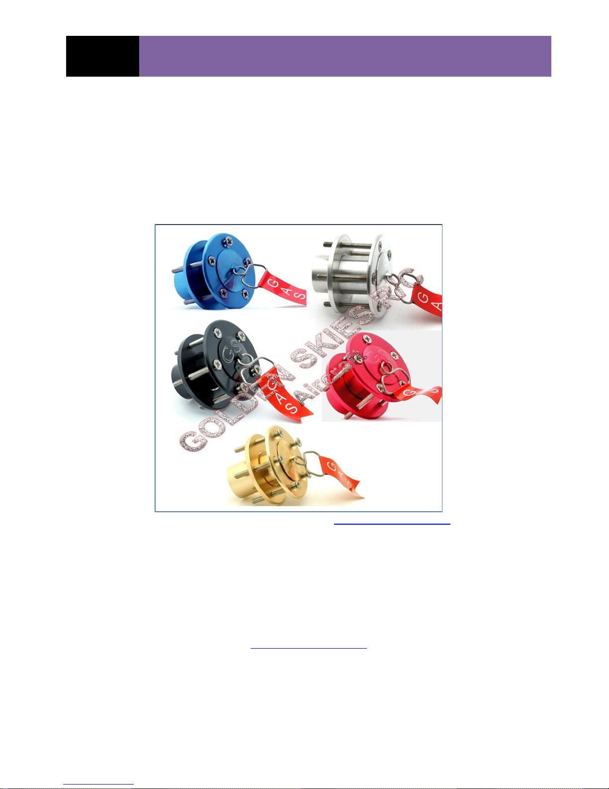
FUEL POINT™:
The proprietary, GOLDEN SKIES R/C AIRCRAFT, INC. Fuel Point™ system pictured below is
the most convenient and popular method of adding gas to your aircraft’s fuel tank. The Fuel
Point™ is installed as shown in the diagram under this manual’s “Tank Installation and
Plumbing” Section, or may be downloaded from the www.goldenskiesrc.com . The Fuel Point™
provides fueling through a dedicated fuel line, thus filling the fuel tank directly and without
forcing gas into the carburetor and possibly flooding the engine. It also eliminates extra
plumbing elements such as a “Tee-connector” in the tank-to-carburetor fuel line. This reduces
the possibility of air leaks or perhaps a total disconnection of the main engine fuel supply. The
GS R/C Fuel Point™ functionality is sometimes referred to as “Fuel Dots.”
$19.99, plus S&H from GOLDEN SKIES R/C Aircraft, Inc.
(Prices subject to change without notice in this Operation Manual)
www.goldenskiesrc.com
06/29/2016 Copyrighted Material
Owner’s Manual All Rights Reserved 03180-10000
Page - 7 DLA 32, 58, 64, 64-I2, 116, 116-I2 & 128cc, 180c, 232cc Rev. A.05.11
GS R/C
DLA ENGINE OPERATING-INSTRUCTION
MANUAL
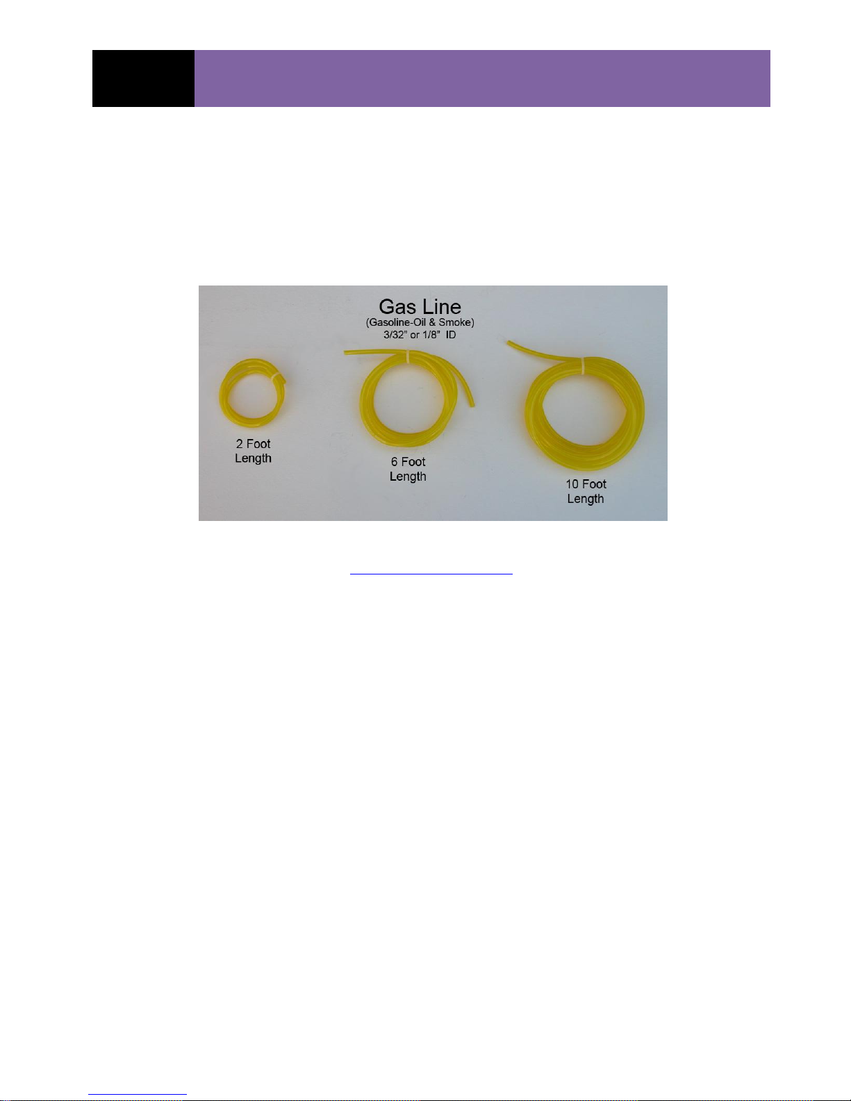
GAS LINE:
The fuel line must be compatible with the Gasoline-Oil mixture used for DLA Engines. GOLDEN
SKIES R/C AIRCRAFT, INC. provides one of the best composite Tygon®-PVC fuel line materials.
The GOLDEN SKIES R/C AIRCRAFT, INC. fuel line tends to remain more flexible over a longer
time period.
Available from Golden Skies R/C Aircraft, Inc.
www.goldenskiesrc.com
OIL:
There are several good manufacturers of 2-cycle oil available. GOLDEN SKIES R/C AIRCRAFT,
INC. does not, at the time of this Manual Revision (A.05) sell or distribute 2-cycle oil.
MOUNTING (Engine) TEMPLATE:
An optional, laser cut, engine mounting template is available from Golden Skies R/C Aircraft, Inc.
The template is universal and applicable for all DLA engines addressed by this current manual
revision. The GS R/C – DLA Engine mounting template is the most accurate way to locate the
mounting hole-centers on the aircraft's firewall or engine box.
06/29/2016 Copyrighted Material
Owner’s Manual All Rights Reserved 03180-10000
Page - 8 DLA 32, 58, 64, 64-I2, 116, 116-I2 & 128cc, 180c, 232cc Rev. A.05.11

GS R/C
DLA ENGINE OPERATING-INSTRUCTION
MANUAL
Most aircraft manufactures will provide both Vertical and Horizontal alignment lines (V
H
on the firewall. The template has corresponding V
c/l)
and H
c/l
lines which are aligned to those
c/l
c/l
and
scribed on the firewall to accurately locate mounting hole. A paper mounting guide is provided at
the end of this operation manual, but is not as accurate.
Laser Cut Template is available through Golden Skies R/C Aircraft, Inc.
www.goldenskiesrc.com
PN: 03180-50005-A ($9.99)
DRILL BIT GUIDE – (for Propeller Bolts)
Specifically engineered Drill Bit Guides (DBG) for each DLA Engine are the preferred and most
accurate method for locating and drilling the holes in the propeller hub for the Propeller Bolts.
06/29/2016 Copyrighted Material
Owner’s Manual All Rights Reserved 03180-10000
Page - 9 DLA 32, 58, 64, 64-I2, 116, 116-I2 & 128cc, 180c, 232cc Rev. A.05.11

GS R/C
DLA ENGINE OPERATING-INSTRUCTION
MANUAL
Shown above is the DBG for the DLA 32cc gas engine. The centering tab on the back of the DBG is
inserted in the prop’s crankshaft hole and the engraved arrows, aligns with the prop’s axis. The
first hole is drilled, using the specified drill bit (see Prop-drill bits below) and then the
alignment/anchoring pin is inserted through the DBG and propeller to secure the DBG while the
remaining holes are drilled.
The GS R/C – DLA Drill Bit Guide is available through www.goldenskiesrc.com
Drill Bits:
GOLDEN SKIES R/C AIRCRAFT, INC. stocks metric drill bits in the precise sizes
to match the specific propeller bolts for each of the DLA Engines:
DLA 32cc 4.2 mm GS R/C #: 03180-50001 ($20.99)
DLA 58cc 5.2 mm GS R/C #: 03180-50002 ($20.99)
DLA 64cc 5.2 mm GS R/C #: 03180-50002 ($20.99)
DLA116cc 5.2 mm GS R/C #: 03180-50002 ($20.99)
All DLA Engines have a ten (10) mm crankshaft diameter. The propeller’s
crankshaft hole should be sized to ten (10) mm. The appropriate drill bit is:
10 mm x - 135o GS R/C # 01380-50003
Propeller Bolts:
GOLDEN SKIES R/C AIRCRAFT, INC. stocks the proper Propeller Bolts for each of the DLA
Engines. It is important to use only the specified propeller bolts for proper diameter, threadpitch, strength and operation.
The specified prop-Bolts are:
DLA 32cc PN: 01380-00102
DLA 58cc PN: 01380-00202
DLA 64cc PN: 01380-00302
DLA 116 / 116-I2cc PN: 01380-00402
DLA 128cc PN: 01380-00502
PROPELLERS:
The propeller brand selection is somewhat a personal preference and is generally guided by
personal experience and the type of flying desired. Several good propeller manufacturers are
available. Some of the known propeller manufacturers are:
1) Menz 2 ) Mejzlik 3) Beila4) APC 5) Xoar 6) NX
06/29/2016 Copyrighted Material
Owner’s Manual All Rights Reserved 03180-10000
Page - 10 DLA 32, 58, 64, 64-I2, 116, 116-I2 & 128cc, 180c, 232cc Rev. A.05.11

GS R/C
DLA ENGINE OPERATING-INSTRUCTION
MANUAL
SPINNERS:
A sturdy, light weight spinner is best, but they tend to be rather expensive. GOLDEN SKIES R/C
AIRCRAFT, INC. offers lower cost spinners. Please refer to the GOLDEN SKIES R/C AIRCRAFT,
INC. website for spinner selections from two (2) inch to four (4) inch diameter.
www.goldenskiesrc.com/Product_page_Spinners.html
The prop-nut shown on the lower left is not required for DLA Engines; however, you will still
secure the spinner using the “Spinner-bolt” shown on the lower right. The tip of the engine’s
crankshaft is drilled and tapped for a 5.0 mm x 0.8 mm bolt. The length of the spinner-bolt will
depend upon the spinner size.
Spinner Bolts: GS R/C has a stock of spinner-bolts in various lengths. Visit the Golden
Skies R/C Aircraft website to purchase. www.goldenskiesrc.com
06/29/2016 Copyrighted Material
Owner’s Manual All Rights Reserved 03180-10000
Page - 11 DLA 32, 58, 64, 64-I2, 116, 116-I2 & 128cc, 180c, 232cc Rev. A.05.11
GS R/C
DLA ENGINE OPERATING-INSTRUCTION
MANUAL
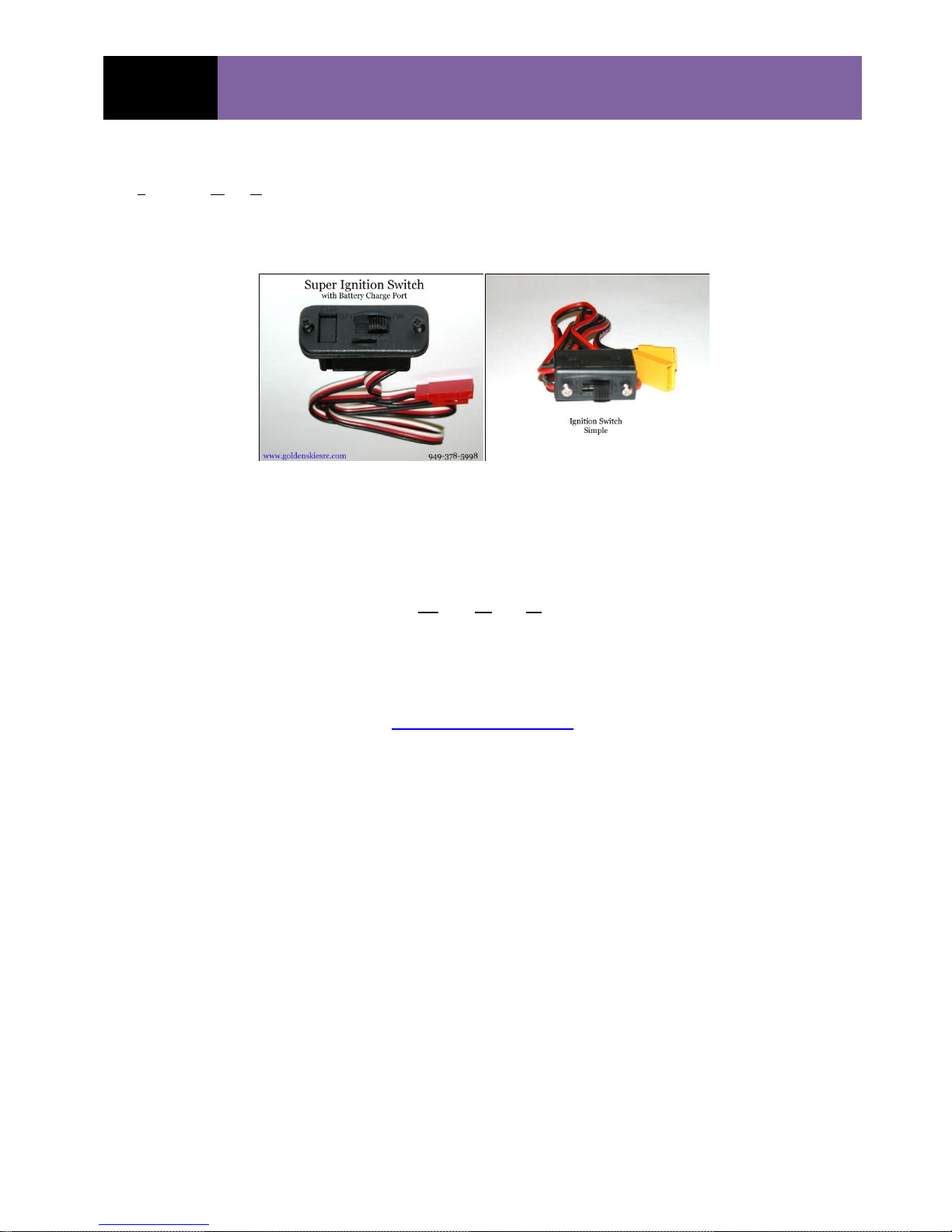
IGNITION SWITCH:
An Ignition “Kill” Switch (IKS) is required for all DLA Engine / Ignition Installations. Refer to
the installation procedures and diagrams in the “Ignition Installation and Wiring” Section.
GOLDEN SKIES R/C AIRCRAFT, INC. offers the switches that are most commonly used for the
IKS:
IGNITION BATTERY:
All DLA Engine Ignitions operate within a 6.6 V DC to 8.4 V DC range. A 2-Series, LiPo is
commonly used. However, good quality Nickel-Metal-Hydride (NiMH) battery, in a six- (6)
series configuration, is also adequate. An 1100 mAh battery is sufficient. However, a 2100 mAh
battery is recommended for the 64cc and 116cc engines. Check the Golden Skies R/C Aircraft
website for battery selections. The CDI will not operate under 6.0 VDC and damage to the CDI
may occur if the CDI supply voltage is less than 6.0 VDC.
www.goldenskiesrc.com
BOLT SET (Engine):
Complete DLA Engine bolt sets are available for each DLA engine. The Engine bolt set includes
Mounting bolts, prop-bolts, muffler bolts, and appropriate flat-washers and lock-washers.
DLA 32cc PN: 01380-00103
DLA 58cc PN: 01380-00203
DLA 64cc PN: 01380-00303
DLA 116cc PN: 01380-00403
DLA 116 I2cc PN: 03180-01412
DLA 128cc PN: 03180-01624
----------------------------------END OF ACCESSORIES------------------------------------
06/29/2016 Copyrighted Material
Owner’s Manual All Rights Reserved 03180-10000
Page - 12 DLA 32, 58, 64, 64-I2, 116, 116-I2 & 128cc, 180c, 232cc Rev. A.05.11
GS R/C
DLA ENGINE OPERATING-INSTRUCTION
MANUAL
ABOUT DLA ENGINES:
The DLA Engine has been specifically designed, developed and manufactured from proprietary
components for larger (32cc and up) size Model Aircraft. The DLA series of engines are very
powerful, exceptionally light weight for its class, easy to operate and adjust. DLA engines should
provide years of satisfactory performance, if maintained properly. DLA Engines are manufactured
by FeiaoModel in China. See warranty.
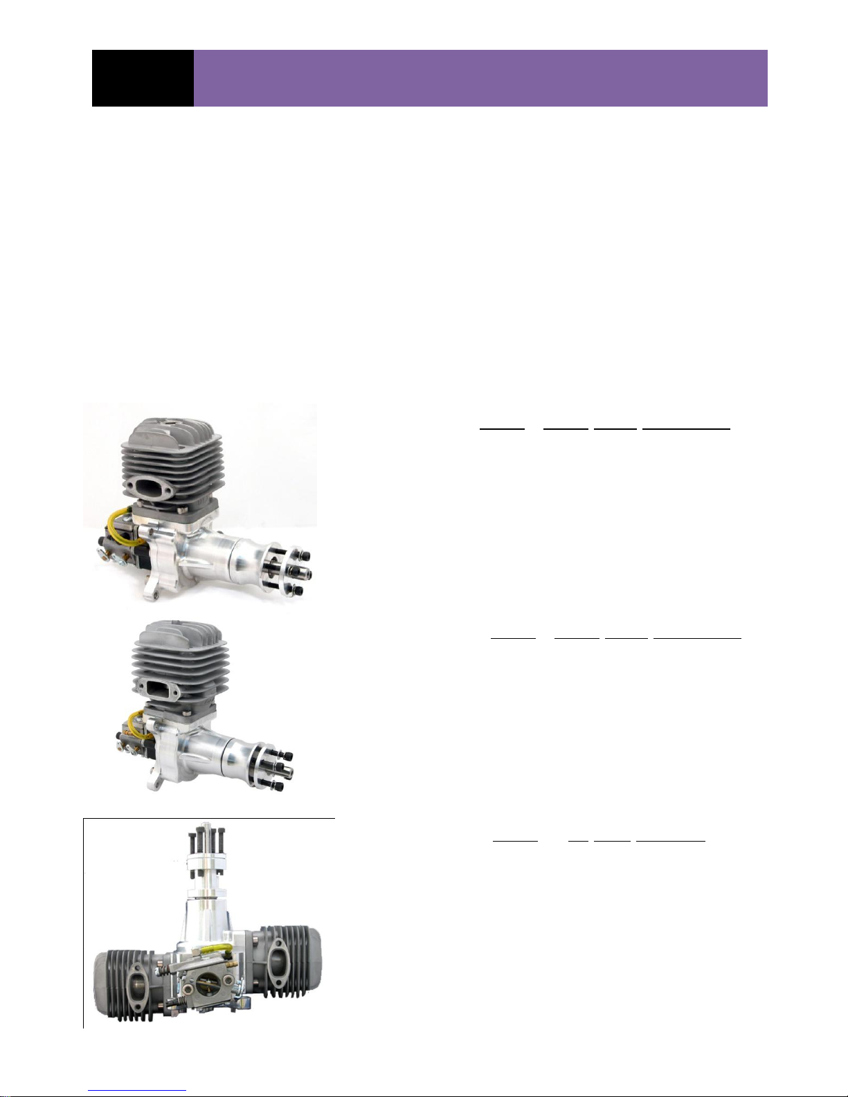
Technical Specifications: (See Table 2 for more comprehensive list of Specifications)
DLA - 32cc GAS ENGINE
Displacement: 32cc (1.95 in
Horsepower: 3.8 Hp @ 8,200 rpm
Idle: 1,700 rpm
Static Thrust: 19.4 pounds (Pulling Force)*
Props: 18x8, 18x10, 19x8, 20x8
Compression: 7.6 : 1
Spark Plug: CM6-Special, Iridium
Cyl. Dia / Stroke: 37 / 30 mm (1.46” / 1.18”)
Gas:Oil Ratio: 45:1 Typical (Flying)
Weight: 44.6 oz (2.79 lb) (All Components)
3
)
DLA - 58cc GAS ENGINE
Displacement: 58cc (3.42 in
Horsepower: 6.0 Hp @ 8,500 rpm
Idle: 1,400 rpm
Static Thrust: 33.1 pounds (Pulling Force)*
Props: 22 x 10, 23 x 8/10, 24 x 8
Compression: 7.8 : 1
Spark Plug: CM6-Special, Iridium
Cyl. Dia / Stroke: 46 / 35 mm (1.77” / 1.38”)
Gas:Oil Ratio: 45:1 Typical (Flying_
Weight: 63.1 oz (3.94 lbs) (All Components)
3
)
DLA 64cc Gas Engine
Displacement: 64cc (~3.97 in
Horsepower: 7.2 @ 8,500 rpm
Idle: 1,400 rpm’
Static Thrust: 34.4 pounds -Pulling Force
Props: 22x10, 23x8 /10, 24x8
Compression: 7.8 : 1
Spark Plug: CM6-Special, Iridium
Cyl. Dia / Stroke: 37 / 30 mm (1.46”/ 1.18”)
Gas:Oil Ratio: 45:1 Typical (Flying)
06/29/2016 Copyrighted Material
Owner’s Manual All Rights Reserved 03180-10000
Page - 13 DLA 32, 58, 64, 64-I2, 116, 116-I2 & 128cc, 180c, 232cc Rev. A.05.11
3
)

GS R/C
DLA ENGINE OPERATING-INSTRUCTION
MANUAL
Weight: 72.4 oz (4.5 lbs) (All Components)
DLA 116cc Twin Boxer
Displacement: 116cc (6.83 in
Horsepower: 11.8 @ 7500 rpm
Idle: 1300 rpm
Static Thrust: 59.9 pounds - pulling Force
Props: 26 x 10/12, 27 x 10, 28 x 10
Compression: 7.8 : 1
Spark Plug: CM6-Special, Iridium
Cyl. Dia / Stroke: 46 / 35 mm (1.78”/ 1.38”)
Gas:Oil Ratio: 45:1 Typical (Flying)
Weight: 107.6oz (6.72 lbs) (All Components)
DLA 116cc In-Line Twin
3
)
Displacement: 116cc (6.83 in
Horsepower: 11.8 @ 7,500 rpm
Idle: 1,300 rpm
Static Thrust: 59.9 pounds (Pulling Force)
Props: 26 x 10/12, 27 x 10, 28 x 10
Compression: 7.8 : 1
Spark Plugs: CM6 – Special, Iridium
Cyl. Dia / Stroke: 46 / 35 mm (1.78: / 1.38”)
Gas: Oil Ratio: 45 : 1 Typical (Flying)
Weight: 122.1 oz (7.63 lbs) oz (All Components)
DLA 128cc QUAD BOXER
Displacement: 128cc (7.94 in
Horsepower: 13 hp
Idle: 1,250 rpm
Static Thrust: 61 pounds @ 100m (~328 ft)
Props: 27 x 10/12, 28 x 10, 29 x 12
Compression: 7.8 :1
Sparkplugs: CM6 – Special, Iridium
Cyl. Dia / Stroke: 37 / 30 mm (1.46”/ 1.18”)
Gas : Oil 45 : 1 Typical (Flying)
Weight: 148.5 oz (9.29 lbs) (All Components)
3
)
3
)
*Typical Value, User Thrust will vary dependent upon, Propeller, rpm and numerous other factors.
06/29/2016 Copyrighted Material
Owner’s Manual All Rights Reserved 03180-10000
Page - 14 DLA 32, 58, 64, 64-I2, 116, 116-I2 & 128cc, 180c, 232cc Rev. A.05.11

GS R/C
DLA ENGINE OPERATING-INSTRUCTION
MANUAL
ITEMS INCLUDED IN THE RETAIL ENGINE BOX WHEN SHIPPED:
The following items are in the retail box. Any missing or damaged parts must be reported to
GOLDEN SKIES R/C AIRCRAFT, INC. within seven (7) days of the original purchase date to make
a claim for replacement(s):
1. Engine, 1-each
a. Sparkplug, 1-ea DLA 32, 58, and 2-ea DLA 64cc & 116cc, 4-ea 128 QUAD
b. Prop-Washer, 1-each
c. Prop Bolts, 4-each, DLA 32, 58, 64cc and 6-each DLA 116cc, 128 QUAD
d. Ignition Pick-up Sensor and Wire Lead, (2-ea on 64, 116cc, 128QUAD eng.)
e. Carburetor(s)
2. Muffler(s)
a. Gasket, 1-each DLA 32, 58, and 2-each DLA 64cc, 116cc, 4-ea 128cc QUAD
b. Mounting bolts, 2 each DLA 32, 58, and 4 each DLA 64cc, 116cc
3. Ignition, 1-each on 32, 58, 64, 116 Twin, 2-ea on 116-IL & 128 QUAD
a. Silicon Pick-up Wire Wrap Protector and connector Safety Clamps
4. Mounts, Engine (Stand-offs), 4-each
a. Mounting bolts, 8-each for DLA32, 58, 64cc and 4-each for DLA 116, 128cc
5. Operating Manual (visit www.goldenskiesrc.com for the most current Revision)
INTENDED ENGINE USE:
DLA, 2-cycle, Gasoline Engines are designed exclusively for installation in and as the propulsion
system for Radio Controlled Model Aircraft. Any other use is prohibited. Installation is described
in this Operations Manual (PN: 03180-1000, Rev. see footnote). It is the responsibility of the
consumer to install the engine properly using the installation guidelines of this manual as a
minimum standard.
SAFETY INSTRUCTIONS:
DLA Gasoline Engines are not toys and can cause serious injury or death when not
used properly and with extreme caution at all times. Adherence to the Safety
Instructions, here-in, as a minimum requirement, is absolutely mandatory. Read
thoroughly, and become intimately familiar with all safety instructions. Initial each line item
to indicate you have read and understand the instruction. If you do not understand any
or all of the Safety Instruction line items, re-read until you do or consult with the American Model
Aeronautics Association. Further, read the entire DLA Engine Operating Manual and be sure you
are totally familiar and understand each and every item. Learn completely the engine’s
application, limitations and possible hazards. Review the Safety Instructions
monthly.
06/29/2016 Copyrighted Material
Owner’s Manual All Rights Reserved 03180-10000
Page - 15 DLA 32, 58, 64, 64-I2, 116, 116-I2 & 128cc, 180c, 232cc Rev. A.05.11

GS R/C
DLA ENGINE OPERATING-INSTRUCTION
MANUAL
1. OPERATE IN WELL VENTILATED AREAS: Make sure the area of operation is
well ventilated. Never operate the engine in an enclosed area.
2. INSPECT ALL BOLT FOR SECURITY: Inspect the engine bolts and all engine
components prior to starting and operating the engine:
a. Check the Security of the prop-bolts.
b. Check the Security of the engine mount bolts.
c. Check the Security of all gas line connections.
d. Check to see that the ignition and ignition battery are firmly secured to the
airframe.
e. Confirm the integrity of and proper connection of all ignition wiring.
f. Check to see that the Muffler is securely attached to the engine.
3. USE ENGINE KILL SWITCH: Always install a manual ignition on-off or
engine “kill” switch on the outside of the aircraft frame and well back of
the engine propeller.
a. A remotely operated “kill” switch, one that is controlled by the RC Transmitter in
addition to the manual Kill Switch may also be advisable.
4. NEVER OPERATE ENGINE ALONE: Always, have a second person restrain the
aircraft when starting the engine.
5. STAY CLEAR OF ROTATING PROPELLER: Do not lean over, stand in front of
or directly to the side of an operating engine. Do not get within two feet of a rotating
propeller and do not reach toward or point toward the rotating propeller.
6. POINT AIRCRAFT AWAY FROM OTHERS: Be sure the aircraft is pointed away
from all others when starting.
7. KEEP SPECTATORS AWAY: Keep all spectators at least thirty (30) feet away
from the engine and aircraft when preparing to start and operating the engine.
8. WEAR PROPER APPAREL: Do not wear loose clothing, gloves, neckties, jewelry,
neck straps, loose shoe strings or any other item that could become entangled in the
engine’s propeller. The above list may not be all inclusive.
9. DO NOT ADJUST ENGINE WHILE RUNNING: Never try to fix, alter or adjust
anything on the aircraft or engine while the propeller is rotating. Always stop the
engine from running (operating) when making adjustment to the engine.
10. WEAR EYE PROTECTION: Always wear eye protection when operating the
engine. A full face shield is preferred.
11. USE CORRECT PROPELLER SIZE: Always use the correct size propeller (see
Propeller Selection).
a. Be sure the propeller is completely balanced.
b. Check the Prop Bolts for security and always use thread locking material on each
Propeller Bolt.
12. USE FACTORY FURNISHED ENGINE BOLTS: Use the proper length propeller
bolts:
a. DLA 32cc 4.0 mm x 0.7 mm – 35 mm Steel Bolts
b. DLA 58cc 5.0 mm x 0.8 mm -- 40 mm Steel Bolts
c. DLA 64cc 5.0 mm x 0.8 mm -- 40 mm Steel Bolts
d. DLA 116cc 5.0 mm x 0.8 mm – 50 mm Steel Bolts
13. ENGINE FUEL IS HIGHLY FLAMMABLE AND DANGEROUS: The
Gasoline and Oil, fuel mixture, is highly flammable and dangerous. Keep
the engine fuel container (Gasoline and Oil) in a safe place and at least fifteen (15)
away from the aircraft. Keep the Fuel away from sparks, open flame or anything else
that could accidentally ignite the fuel. Keep fuel away from children. DO NOT
SMOKE within twenty (20) feet of the engine fuel. Have a fire extinguisher on hand.
06/29/2016 Copyrighted Material
Owner’s Manual All Rights Reserved 03180-10000
Page - 16 DLA 32, 58, 64, 64-I2, 116, 116-I2 & 128cc, 180c, 232cc Rev. A.05.11

GS R/C
DLA ENGINE OPERATING-INSTRUCTION
MANUAL
14. OPERATING ENVIRONMENT: Do not operate the engine in the vicinity of loose
materials of any kind, including dirt, sand, gravel, grass (that can reach the propeller),
strings, power cords, and anything else that can be blown by the propeller’s “propwash” or get caught in, sucked into, or reach the operating propeller. The list above is
not all inclusive.
15. BALANCE SPINNER: Always be sure that the spinner is balanced and installed
according to the spinner manufacturer’s instructions. Do not allow the edges of the
spinner’s propeller cut-outs to touch the propeller.
16. DAMAGED PROPELLER OR SPINNER: Never use a damaged propeller or
spinner: Ex: one that has come into contact with the ground or other objects, or has
been involved in a crash. Do not use a propeller that is split, cracked, pitted or has
any other flaws or damage. Follow all Propeller Manufacturer’s instructions.
17. NEVER THROW ANY ITEM INTO SPINNING PROPELLER: Never attempt
to stop the propeller by injecting or throwing anything into a rotating propeller.
18. USE SPECIFIED ENGINE FUEL LINE: Use only approved fuel line that is
suitable for gasoline and oil.
19. ENGINE GETS HOT: The engine is extremely hot after operation. Do not touch the
engine after running. Allow ample time for the engine to cool off prior to touching it.
20. DO NOT REFUEL WHEN ENGINE IS HOT: Never refuel the aircraft while the
engine is still hot. Allow the engine to cool to a comfortable “hand-touchable”
temperature before refueling.
21. REMOVE FUEL BEFORE TRANSPORTING: Remove all fuel from the aircraft
fuel tank and engine prior to transporting the aircraft.
22. USE SPECIFIED ENGINE OIL: Use high-quality, 2-cycle oil when mixing with
the gasoline.
23. USE NON-METALLIC THROTTLE PUSH-RODS: The throttle’s push-rod and
clevises should be non-metallic.
24. FILTER FUEL-GAS: Always filter the engine’s fuel when filling the aircraft’s fuel
tank.
25. COMPONENT LOCATIONS: Mount the ignition battery, kill-switch and throttle
servo at least six to twelve (6 - 12) inches to the rear of the aircraft firewall.
26. KILL SWITCH OPERATION: Stay clear of the propeller when switching the Kill-
switch on or off. Accidental ignition may occur and start the engine.
27. COWL AIR FLOW: Provide for proper venting of the cowl to keep the engine cool
while operating.
28. CLEANLINESS: Keep all engine surfaces clean and free from gasoline, oil or other
debris.
29. SPARKPLUG REMOVED: Do not rotate the propeller with the ignition switched
on, while the sparkplug has been removed. Irreversible damage to the ignition system
will occur.
30. LEAN GAS-MIXTURE DAMAGE: Do not run the engine with a “LEAN” gas
mixture. The engine will overheat and permanent damage will occur.
31. FIRE EXTINGUISHER: Always have a portable fire extinguisher on hand and
readily available. Consult with your local fire authority for the best type with respect
to your flying environment.
06/29/2016 Copyrighted Material
Owner’s Manual All Rights Reserved 03180-10000
Page - 17 DLA 32, 58, 64, 64-I2, 116, 116-I2 & 128cc, 180c, 232cc Rev. A.05.11

GS R/C
DLA ENGINE OPERATING-INSTRUCTION
MANUAL
ENGINE INSTALLATION IN MODEL AIRCRAFT
Mount Engine to Model Aircraft Firewall:
Prior to mounting or re-mounting any DLA engine onto the aircraft, review all safety instructions,
check to be sure all engine bolts, plugs, etc. are securely in place. Check the engine thoroughly for
any damage, cracks, or unusual wear.
1. Install the Silicon Wire-wrap Protector over the ignition pick-up wire. Remove any
excess silicon protector.
2. Mount the engine to the aircraft firewall.
a. The firewall must be at least 3/8” (~9.5 mm) thick and perfectly flat.
b. There are three methods for locating the mounting-hole centers on the firewall:
i. PREFERRED: Use the GS R/C – DLA Engine Mount Template.
ii. ACCEPTABLE: Use the paper template at the end of this manual
1. Check the dimensions on the paper template by measuring between
the appropriate hole-center locations and confirm they are as
specified either on the paper template or per the dimensions on
Table 1. (Paper can shrink and expand and printing may, and often
does vary dimensionally.)
iii. LEAST PREFERRED: Manually measure the hole locations from the V
and H
and mark on the firewall as per the engine mount dimensions given
c/l
in Table 1.
3. Using the template, align the respective V
template or the paper template with the corresponding V
and H
c/l
on the GS R/C – DLA Engine
c/l
and H
c/l
on the aircraft
c/l
firewall.
a. NOTE: Follow the alignment procedures described in the model aircraft assembly
manual. The aircrafts manual instructions should allow for any right or down
thrust that may be built into the aircraft’s firewall.
b. NOTE: The objective is to have the engine’s crankshaft be perfectly
aligned with the aircraft thrust-line at the point where the crankshaft
exits the aircraft’s cowl.
4. When the template is aligned properly to the firewall, mark the four (4) mount holes,
center locations with a center punch or an awl. Center punch the awl marks if needed.
5. Drill the engine firewall, mounting holes, using a drill-bit as follows:
a. DLA 32, 58, 64, 116 cc PN: 03180-50000, 5.2 mm OD, 135
o
6. Install the DLA stand-offs (included), or use stand-offs of a length to specifically match
the requirements of your model aircraft dimensions. (THE WARRANTY DOES NOT
COVER NON-DLA STAND-OFFS OR DAMAGE CAUSE TO THE DLA ENGINE AS A
RESULT OF USING NON-DLA STAND-OFFS.)
c/l
06/29/2016 Copyrighted Material
Owner’s Manual All Rights Reserved 03180-10000
Page - 18 DLA 32, 58, 64, 64-I2, 116, 116-I2 & 128cc, 180c, 232cc Rev. A.05.11

GS R/C
DLA ENGINE OPERATING-INSTRUCTION
MANUAL
a. The cut “squared-off” end of the DLA stand-off attaches to the engine.
b. If additional stand-off length is needed, extra spacers should be placed between the
firewall and the DLA-Stand-off. Extra spacer length such not exceed 10% of the
standoff length. The opposite ends of any spacer must be perfectly parallel, flat and
the diameter should not be less than the DLA Stand-off, flared base.
c. Mount the stand-offs to the firewall and leave the bolts slightly loose for the
moment. Use washers between the bolt-head or nuts and the firewall backside, the
larger in diameter the better…..within reason.
d. Mount the engine to stand-offs using the 4 ea bolts:
i. 5.0 mm x 0.8 mm – 2o mm (DLA 32, 58, 64cc)
ii. 5.0 mm x 0.8 mm – 50mm (DLA 116, 128cc)
7. Check the alignment of the engine, with the cowl mounted, to determine that the
crankshaft is exiting the cowl properly. (See Model Aircraft Assembly Manual for
Details.)
8. Adjust as necessary and secure all bolts.
a. Use lock washers and thread locking compound on all threads.
9. The supplied stand-offs set the minimum distance between engine’s carburetor and the
firewall. If you use non-DLA Stand-offs, do not decrease this distance. If you cannot
maintain this minimum distance, you may want to consider cutting a hole in the
firewall, directly in line with the carburetor with a diameter approximately equal the
diameter of the carburetor’s intake. DO NOT COMPROMISE THE INTEGRITY OR
STRENGTH OF THE FIREWALL. If you have questions about altering the
firewall, check with the model aircraft’s manufacturer or distributor.
10. For the DLA 116cc, where the carburetor generally points downward, there should be
at least 1 to 1-1/2” (~38 mm) between the bottom of the carburetor and the cowl.
11. GENERALLY, THE CARBURETOR INTAKE SHOULD BE SITUATED IN “STILL
AIR”. Swirling or turbulent air in or around the carburetor intake can significantly
disrupt the carburetor operation and the cause poor and/or erratic engine
performance. How the air behaves on the ground and in flight is always different and
you may need to control the airflow in and around the carburetor intake.
12. Take note of the carburetor’s High and Low needle valve locations. To avoid having to
remove the cowl for adjustments, you may want to consider making a hole(s) in the
cowl to access these mixture adjustments. With the cowl on or off, engine performance
often differs. Final adjustments with the cowl in place is often more desirable.
13. COWL Vents and Air Flow: Be sure that the cowl openings are sufficient to provide
adequate airflow across the DLA cylinder head fins. Generally, the “rule-of-thumb” is
to have the air exit holes to be three (3) times the size of the air intake. If the air intake
is too big, sufficient air flow may not be directed over the engine’s cooling fins. In such
cases, some air flow directivity may be required, through the use of “air damns” or
vanes.
06/29/2016 Copyrighted Material
Owner’s Manual All Rights Reserved 03180-10000
Page - 19 DLA 32, 58, 64, 64-I2, 116, 116-I2 & 128cc, 180c, 232cc Rev. A.05.11

GS R/C
DLA ENGINE OPERATING-INSTRUCTION
MANUAL
SPARK PLUG:
Install the Special CM6-Special, Iridium Sparkplug supplied in the engine’s cylinder head. Take
care not to cross-thread the plug. The proper torque for the plug is: 7.5 -> 8.0 ft-lbs (~96 in-lbs,
or ~10.2 Nm) for all DLA Engines. The typical spark-plug gap is: 0.018 –> 0.02 inches. The gap
is set by the manufacturer, attempting to adjust the gag can damage the hard iridium metal.
MUFFLER INSTALLATION:
Attach the DLA muffler to the engine using the two (2) supplied, 5.0 mm x 0.8 mm – 16mm
Socket Head bolts and gasket supplied. No gasket sealant is required. The DLA 64 & 116cc engine
has two (2) mufflers and therefore, four (4) each attachment bolts and two (2) gaskets The 128cc
Quad has eight (8) bolts. Torque each bolt to 60 -> 65 in-lbs (6.7 -> 7.3 N*m). Over torque can
strip the threads. Check bolt tightness after every three or four flights. (see: torques on page 50)
Follow the model aircraft’s assembly manual for providing exit holes for the muffler stacks.
IGNITION INSTALLATION AND WIRING:
All DLA Engine ignition wiring configurations are basically identical. The exception is that the
DLA 64 and 116cc engines have two (2) Ignition or Sparkplug wires running from the Ignition
Module to the two (2) individual Sparkplugs.
Install the ignition in the forward part of the fuselage and isolate it from the airframe with foam
rubber at least 1/2” thick. Secure in place with Velcro® or other like material. Be sure the
location allows all the wiring to reach the intended end points. The ignition wiring diagram is
shown below.
NOTE: When referring to the “SEX” of the connector, it is the connector PINS and Sockets that
determine the sex and not the shape of the connector housing. So, always look at the pins or
sockets. Manual notation is: Male (M) and Female (F). Generally, the sex of the Ignition’s and
the Engine’s connectors are such that they only go together in the correct way.
The step-by-step procedure for the wiring installation is as follows:
1. Step 1: Install the Ignition Kill Switch (IKS) through the side of the fuselage, at a location
easily accessible and safely away from the engine’s propeller.
a. A battery charger connection is built into the ”Super Ignition Switch”.
b. Do not charge a LiPo battery while the battery is in the aircraft. Always remove the LiPo
battery and charge in a fire proof, safe location.
2. Step 2: Connect the IKS “Power Switch Wire” to the “Ignition’s Power Wire”. The Ignition Power
Wire is a two (2) wire lead (Red “+” and Black “-“). An adapter is provided with the engine if
needed. Add a safety clip over the connectors. (Note the optional remote Kill Switch.)
06/29/2016 Copyrighted Material
Owner’s Manual All Rights Reserved 03180-10000
Page - 20 DLA 32, 58, 64, 64-I2, 116, 116-I2 & 128cc, 180c, 232cc Rev. A.05.11

GS R/C
DLA ENGINE OPERATING-INSTRUCTION
MANUAL
3. Step 3: Wrap the small Spiral-Wire-Protection covering around the engine’s pick-up
sensor wire, from the sensor to the connector. Cut off any excess. Then wrap the Ignition’s
Pickup sensor wire and cut off any excess.
4. Step 4: Connect the Ignition’s Timing Pickup wire (F) to the Engine’s Pickup Sensor Wire (M).
5. Step 5: Wrap the large Silicon-Wire-Protection covering over the Ignition’s Sparkplug wire.
a. Take care not to damage the braided wire sleeve on the sparkplug wire. This is both an EMI
shield and the electrical “return path”.
6. Step 6: Connect the optional tachometer in a location that can be seen from outside of the aircraft,
and connect the wires together.
7. Step 7: Push the sparkplug cap over the sparkplug until it “snaps” into place. Check to see
that the cap cannot be removed with a light pulling force. Be sure it is firmly seated.
8. Step 8: Double check that are connections secure and that the electrical polarity
orientation is correct. That is, Red wire to Red wire, black to black and white to white.
9. Step 9: Secure all connections with the connector clips provided.
a. Heat shrink tubing (not supplied) may also be placed over the connections and used
to prevent the connector from coming apart.
10. Step 10: Be sure the IKS is in the OFF-POSITION. Connect the Battery Lead (2-wires) to
the IKS. Be sure RED wire goes to RED wire and Black to Black. The CDI Battery Voltage
is: 6.4 to 8.4 VDC. Operation the CDI at 6.0VDC of less may result in damage to the CDI.
11. Step 11: Dress are wiring such that minimal vibration is present but not so secure as to
cause abrasion.
WARNING: Any time the IKS is in the “ON” position, the ignition is active (armed) and the
engines could be started with any movement of the propeller.
NOTE: The torque on the sparkplug is: 7.5 -> 8.5 ft-lbs.
Male Connector
CDI Voltage: 6.4 – 8.4 VDC
06/29/2016 Copyrighted Material
Owner’s Manual All Rights Reserved 03180-10000
Page - 21 DLA 32, 58, 64, 64-I2, 116, 116-I2 & 128cc, 180c, 232cc Rev. A.05.11

GS R/C
DLA ENGINE OPERATING-INSTRUCTION
MANUAL
The above CD Ignition pictures are the most current configurations, older CDI’s may vary; check the connector sex for
correct “Sensor, Tachometer & Battery” wiring. Note: The tachometer wire gauge is slightly less than the Sensor wire
gauge. DO NOT USE AN RCEXL TACHOMETER WTH DLA CD IGNITIONS.
06/29/2016 Copyrighted Material
Owner’s Manual All Rights Reserved 03180-10000
Page - 22 DLA 32, 58, 64, 64-I2, 116, 116-I2 & 128cc, 180c, 232cc Rev. A.05.11

GS R/C
DLA ENGINE OPERATING-INSTRUCTION
MANUAL
Engine Disp.
Timing before TDC
1st Cylinder of Bank
2nd Cylinder or Bank
32cc
28 - 32O (30
O
Typ)
58cc
28 - 32O (30
O
Typ)
64cc
28 - 32O (30
O
Typ)
116cc Twin
28 - 32O (30
O
Typ)
116cc IL 30O Typ
28-29O
128cc QUAD
30O Typ
28-29O
Note: Increasing the angle is said to be “Advancing” the time and decreasing the angle is said to
be “Retarding” the timing.
where “x” is proportional to the ignition battery voltage
+ x V
~ 0 VDC
The timing is set on the negative
edge of the pulse, where the
magnet disengages the sensor
Where the magnet 1
st
stimulates the sensor
IGNITION TIMING, SENSOR: (How to set the timing sensor)
The sensor timing is set at the factory to ~ 30
O
before TDC, and you should not have to be reset it.
If you do not have the proper tools and experience with setting the timing, you may be better off
leaving it alone. Never-the-less, depending upon several factors including: altitude, temperature,
ultimate tuning for specific application such as racing, you may want to adjust the timing. Be sure
to check the sensor screws to be sure they are tight and mark the sensor edges on the crankcase
with a felt pen or scribe for reference before proceeding. This manual will offer only limited
timing information and if you feel you need to adjust the time, please contact GS R/C and we may
be able to provide more definitive information, depending on your situation.
The sensor timing is set in degrees (
O
) of crankshaft rotation (counter clock-wise), before Top-Dead-
Center (TDC). TDC is when the piston is at the furthest travel toward the top of the cylinder. A
magnet, which is pressed into the prop-hub, follows the top of the piston and will typically align
with a “landmark” on the crankcase at TDC. As the magnet passes under the sensor, it stimulates
the sensor and sensor generates an electrical pulse which the CDI uses to create a spark in the
sparkplug. The sensor’s electric pulse is represented in the diagram below. The pulse can be
several degrees wide; so, it is important to set the timing on the negative edge of the pulse which is
position where the magnet is “leaving” the sensor.
The timing pulse occurs on the “white-wire”, where the Red = Power, and the Black = Ground-
return. Rotate the prop-hub to the position where the piston is at TDC.
The 116cc, In-line and 128cc QUAD engines have two (2) sensors and two (2) CDI’s and each must
be set separately, see table below. The In-line and the QUAD sensor settings are 180O apart and
each sensor is set specifically for the cylinder or cylinder bank that particular sensor is controlling.
.
With the In-Line and the QUAD engines, it is often advisable to set the 2nd cylinder (rear) or 2nd
cylinder bank, 1-3O retarded with respect to the 1st cylinder/bank. This is done to help keep the 2nd
cylinder/bank cool, as these cylinders are in the “hot-air shadow” of the front cylinder/bank.
06/29/2016 Copyrighted Material
Owner’s Manual All Rights Reserved 03180-10000
Page - 23 DLA 32, 58, 64, 64-I2, 116, 116-I2 & 128cc, 180c, 232cc Rev. A.05.11

GS R/C
DLA ENGINE OPERATING-INSTRUCTION
MANUAL
Special consideration for cooling the 2nd cylinder/bank (rear) should always be addressed. (See
Cowl Ducting and Air Flow below.)
116-I2 and the 128cc QUAD: CONNECTING THE TWO (2), CDIs TO THE PROPER SENSOR
The 116-I2 In-line and the 128cc QUAD have two (2) sensors and two (2) ignitions to drive the
front and rear cylinders separately. The paired combinations of one each sensor and one ignition
is dedicated specifically to the front or rear cylinder bank(s). Therefore, you must connect the
front cylinder’(s) sensor/ignition to the front cylinder(s) and the rear sensor/ignition to the rear
cylinder(s). The 116-I2 and 128cc sensors are typically mark with an “F” or “R” to denote which
sensor goes with the designated cylinder(s) bank (front or rear). See pictures below.
If the crankcase should not be marked with an “F” or “R”, then refer to the pictures for the correct
sensor identification. Another way to identify the front sensor is to rotate the crankshaft so that
the front cylinder-piston is at top-dead-center (TDCf). Note the location of the timing magnet on
the prop-hub. The magnet will be located just CCW from the front sensor. The magnet will be
~28-30O CCW relative to the front sensor.
CAUTIONS:
1. Advancing the timing causes the engine to run hotter. (See Temperature Limits)
2. Advancing the timing typically increases the power…. to a limit.
3. Advancing the timing, may make the engine harder and more dangerous to start.
4. Advancing the timing is harder on the engine and advancing beyond 32
warranty.
COWL DUCTING and AIR FLOW
Be sure that the cowl openings are sufficient to provide adequate airflow across the DLA cylinder
head’s, cooling fins. Generally, the “rule-of-thumb” is to have the air exit holes to be three (3)
times the size of the air intake. If the air intake is too big, sufficient air flow may not be directed
O
voids the
06/29/2016 Copyrighted Material
Owner’s Manual All Rights Reserved 03180-10000
Page - 24 DLA 32, 58, 64, 64-I2, 116, 116-I2 & 128cc, 180c, 232cc Rev. A.05.11

GS R/C
DLA ENGINE OPERATING-INSTRUCTION
MANUAL
over the engine’s cooling fins. In such a case, some air flow directivity may be required, through
the use of “air damns” or vanes.
The QUAD and the In-Line engines require special air flow considerations. Since both types have
one or more rear cylinders that are in the “hot-air shadow” of the forward cylinder(s), it is the
pilot’s responsibility to provide adequate cool air flowing across the rear cylinders.
In the case of the QUAD, one typically directs the airflow from the cowl intake to an area
(chamber) above the cylinder heads and then directs the air to flow downward across both
forward and rear heads. (See diagram)
The same airflow principals would also apply to the 116cc In-Line engine.
TEMPERATURE, ENGINE, LIMITS:
The engine head temperature should never be allowed to reach or exceed 120O C (248O F) and the
crankcase should be restricted to 70O C (158O F). Here is where some temperature measurements
and perhaps temperature telemetry might be quite useful. On hot flying days, > 95O F, you may
consider richening the “rear” carburetor’s high-end needle and reduce the rpm by ~ 200 to help
cool the engine.
06/29/2016 Copyrighted Material
Owner’s Manual All Rights Reserved 03180-10000
Page - 25 DLA 32, 58, 64, 64-I2, 116, 116-I2 & 128cc, 180c, 232cc Rev. A.05.11

GS R/C
DLA ENGINE OPERATING-INSTRUCTION
MANUAL
Fuel – GAS (Type of Gas and Oils Mixture Ratios)
Well filtered (~ 10 microns), 87 Octane (89 Octane is acceptable) Gasoline is recommended for all
DLA Engines. Higher Octane ratings (Aviation Gas) will not improve the engine performance, and
may cause the engine to perform more poorly, run slower and most often overheat. Ethanol
content of Gas in excess of 10% will void the warranty. Select a good quality, 2-cycle oil, and mix
the oil and gasoline to the following ratios:
o Break-in and Trial Running: 25:1 to 30:1 Gasoline:Oil
30:1 is preferred
Use ONLY Carbon Based, 2-cycle oil for break-in
o Typical Flying: 40:1 to 50:1 Gasoline:Oil
45:1 is Typical
Engine or Carburetor damage caused by fuel additives, such as nitro, alcohol, or other ingredients
are not covered under the warranty. Running the improper gasoline to oil mixture ratio, running
the carburetor’s high-end adjustment at a too lean setting, overly-advancing the timing and engine
over heating are not covered by the warranty.
A Chart of Gasoline to Oil mixture ratios is provided at the end of the manual for your
convenience, on the last page of the manual.
TANK INSTALLATION and PLUMBING:
DLA Engines typically burn fuel at a rate, generally measured, in ounces per minute, at full
throttle, as shown in the list below. The selection of the tank size is determined by several factors,
such as:
How long do you want to fly and what fuel reserve you want to maintain:
o Ex: for a DLA 32 at 0.6 oz/min, a desired flight time of twenty (20) minutes and a
5% reserve …. A 14 to 16 oz tank would be required. (0.6x 20 x 1.05 = 13 oz )
Fuel Consumption by engine displacement:
o DLA 32cc 0.50 – 0.7 oz per minute (Typ, Set up & rpm dependent)
o DLA 58cc 0.60 – 0.8 oz per minute (Typ, Set up & rpm dependent)
o DLA 64cc 0.67 – 0.9 oz per minute (Typ, Set up & rpm dependent)
o DLA116 Twin & IL 0.85 – 1.2 oz per minute (Typ, Set up & rpm dependent)
o DLA128cc 1.20 – 1.4 oz per minute (estimated)
The gas or fuel tank is typically placed with the tank’s center located over the aircraft’s Center of
Gravity (C/G) point, thus assisting in lessening the effect on the aircraft’s pitch-moment as fuel is
consumed from the tank. DLA engines have a “diaphragm-type” pump in the carburetor and thus
the relative level of the tank’s, fuel exit point to the carburetor’s in-take point is not critical.
However, keeping these two points at the same level can be desirable. The tank and tank
“stopper” material must be compatible with gasoline. (Silicon tubing is NOT suitable for gasoline
use.)
06/29/2016 Copyrighted Material
Owner’s Manual All Rights Reserved 03180-10000
Page - 26 DLA 32, 58, 64, 64-I2, 116, 116-I2 & 128cc, 180c, 232cc Rev. A.05.11
GS R/C
DLA ENGINE OPERATING-INSTRUCTION
MANUAL
The gas line or “hose” material must be Tygon® or a similar material that is completely
compatible with gasoline and the type of oil used. It is recommended that the gas line shown in
the “ACCESSORIES” section of this manual be used. This gas line is available from Golden Skies
R/C Aircraft, Inc. The gas or fuel lines inside diameter (ID) should be at least as big as the
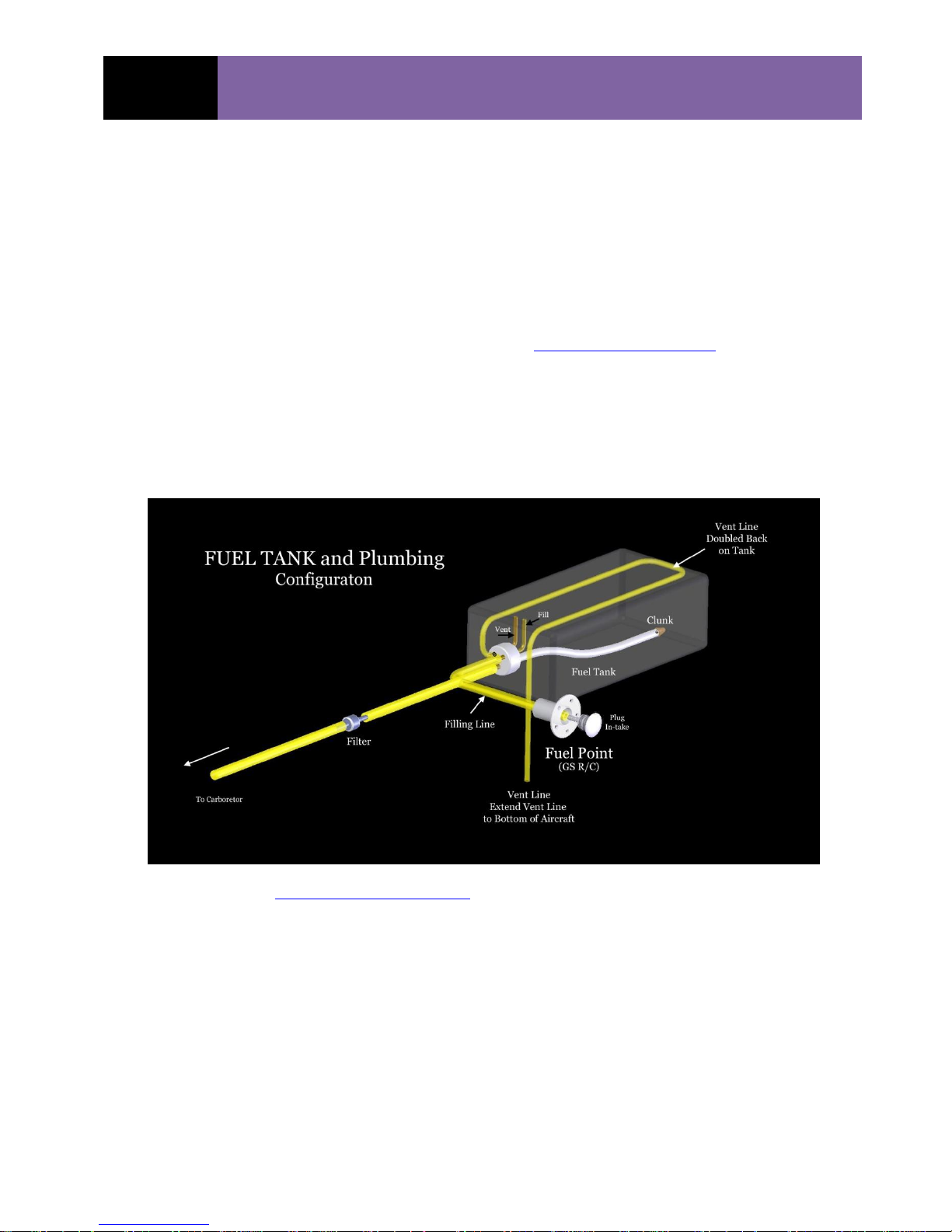
carburetor’s inlet nozzle diameter. The tank is shown to be semitransparent so one may see the
plumbing inside the tank. The vent line is located on the outside-top of the tank and vents to the
bottom of the aircraft.
The preferred fuel tank, gas line plumbing, and Fuel Point connections are shown in the following
diagram. (See GS R/C Website for additional pictures) www.goldenskiesrc.com The In-Line and
128cc QUAD dual carburetors may be supplied with gas by any of the following methods:
1. Single tank with one clunk & line and a “Tee” splitter to each carburetor, 1/8” ID line
2. Single tank with dual clunks and lines, one to each carburetor, 3/32” or 1/8” ID lines
3. Dual tanks, each with a single clunk/line to each of the two carburetors, 3/32” or 1/8”
ID lines
See www.goldenskiesrc.com for other view of tank diagram
FILTER, GAS:
It is mandatory that you filter the gasoline from the source as it is pumped into the aircraft’s fuel
tank. Failure to do so can damage the carburetor and cause engine failure.
One may also place an in-line fuel filter between the aircraft’s fuel tank and the carburetor. The inline filter must not restrict the free fuel flow from the aircraft’s fuel tank to the carburetor. An inline filter must be periodically cleaned by back flowing clean gasoline backwards through the inline filter. Remove the in-line filter from the carburetor supply line prior to cleaning. Never, clean
06/29/2016 Copyrighted Material
Owner’s Manual All Rights Reserved 03180-10000
Page - 27 DLA 32, 58, 64, 64-I2, 116, 116-I2 & 128cc, 180c, 232cc Rev. A.05.11

GS R/C
DLA ENGINE OPERATING-INSTRUCTION
MANUAL
Menz
Xoar
Vess
Mejzlik
APC
Airmodels
Boala
NX
Vess
backward into the aircraft’s fuel tank. Re-flush clean gas, forward through the in-line filter prior
to re-installing the filter in the aircraft.
Many good filters are available commercially, consult your local hobby shop.
FUEL POINT™
The Golden Skies R/C Aircraft, Fuel Point™ is specifically designed to make it easy to add gas to
the aircraft’s fuel tank. The Fuel Point™ consists for two components, 1) The barrel which
mounts to the aircraft cowl or fuselage, and 2) the “Plug” that seals the gas filling line and slips
into and out of the barrel. The plug is double O-ring sealed for security and has a removable flag
on the surface that may be used to indicate whether the aircraft has or has not been re-fueled. The
operation is to feed the Tygon® fuel line from the tank, through the barrel and attach it to the
plug’s barbed nipple. The plug is then inserted into the barrel for a smooth and sleek appearance
on the fuselage surface. When fueling, pull the plug from the barrel, detach the fuel line from the
nipple, and insert the fuel source nipple into the fuel source line. Fuel is then added to the tank,
until the fuel flows out of the vent line, indicating the tank to be full. Always “catch” the overflow
as to not pollute the environment.
PROPELLER SELECTION:
The recommended propellers are as listed below:
DLA 32cc 18 x 8/10, 19 x 8, 20 x 8 (Diameter (in) x Pitch / Pitch range)
DLA 58cc 22 x 10, 23 x 8/10, 24 x 8 (Diameter (in) x Pitch / Pitch range)
DLA 64cc 22 x 10, 23 x 8/10, 24 x 8 (Diameter (in) x Pitch / Pitch range)
DLA 64-I2 22 x 10, 23 x 8/10, 24 x 8 (Diameter (in) x Pitch / Pitch range)
DLA 116cc 26 x 10/12, 27 x 10, 28 x 10 (Diameter (in) x Pitch / Pitch range)
DLA 116-I2 27 x 10/12, 28 x 10, 29 x 10 (Diameter (in) x Pitch / Pitch range)
DLA 128cc 27 x 10/12, 28 x 8/10, 29 x 10 (Diameter (in) x Pitch / Pitch range)
DLA 180cc 32 x 10/12/14, 33 x 10 (Diameter (in) x Pitch / Pitch range)
DLA 232cc 34 x 10, 35 x 10 / 12, 36 x 10 (Diameter (in) x Pitch / Pitch range)
Some the acceptable propeller manufacturers are:
Use of propeller sizes other than those specified above may either “load” or “un-load” the engine
and cause damage. Un-loading the engine has the greater potential to increase the engine’s rpm
higher than recommended or safe for the engine. The prop type and styles may have the same
“loading” and “un-loading” effect, so always check the engine’s rpm with a tachometer. ALWAYS
CHECK AND RE-TIGHTEN THE PROP-BOLTS AFTER EVERY TWO OR THREE FLIGHTS.
06/29/2016 Copyrighted Material
Owner’s Manual All Rights Reserved 03180-10000
Page - 28 DLA 32, 58, 64, 64-I2, 116, 116-I2 & 128cc, 180c, 232cc Rev. A.05.11
GS R/C
DLA ENGINE OPERATING-INSTRUCTION
MANUAL
DRILLING PROPELLER:
The most reliable, consistent and safe way to drill the prop-bolts hole in the propeller is the use
the GS R/C – DLA PROP HOLE DRILL GUIDE. Any other method is not recommended and can
produce results that are unpredictable and potentially dangerous.
1. Place the GS R/C-DLA Prop drill guide into the propeller’s center hole. Often, propellers
have the center or crankshaft hole pre-drilled to ten (10) mm diameter. If the prop’s
center hole is not ten (10) mm, it must be drilled to 10 mm. Use only a self-centering 10
mm drill bit to produce the center hole of the proper diameter.
a. Drill the first prop-bolt hole using a drill press.
b. Use a wood back up plate under the propeller to help prevent splintering the
backside of the prop-hub.
2. Place the alignment pin in the hole just drilled, passing it through the Drill-Guide and into
the prop. This secures the Drill-Guide.
3. Drill remaining holes.
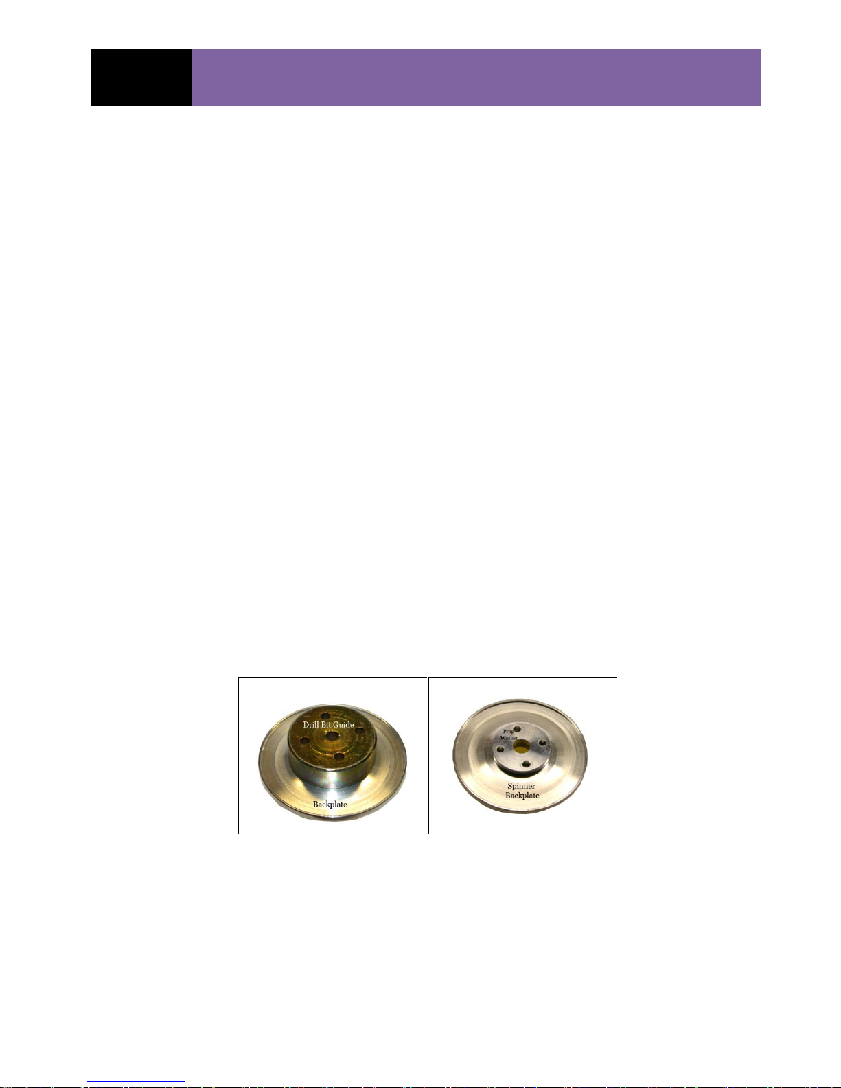
DRILLING SPINNER BACK-PLATE:
Most spinner back-plates are not specific as to the angular position of the back-plate relative to
the spinner cone and thus the prop-hole locations in the back-plate are not critical. Some backplates are solid and some have multiple holes in them for lightening. In the case of the ones with
lightening holes, check to see if the existing holes will align with those required for the prop bolts.
Otherwise, use either the PROP-BOLT DRILL BIT GUIDE or the engines front prop washer to
mark the hole locations and drill with at least one to two (1 -2) millimeter clearance all around.
When mounting the spinner, be sure the spinner back-plate holes are not in contact with the prop
bolts.
ENGINE STARTING:
General:
Sometimes, when the engines have been dormant for a period of time, such as sitting in the
vendor’s warehouse, winter storage, etc., the carburetor gaskets can dry-out and be just a bit less
06/29/2016 Copyrighted Material
Owner’s Manual All Rights Reserved 03180-10000
Page - 29 DLA 32, 58, 64, 64-I2, 116, 116-I2 & 128cc, 180c, 232cc Rev. A.05.11

GS R/C
DLA ENGINE OPERATING-INSTRUCTION
MANUAL
flexible than when lubricated with the gas/oil mixture. In order to pump the gas/oil from the
tank, a considerable amount of hand cranking may be required to draw the gas from the tank to
the carburetor’s nipple and then into the carb’s reservoir. Possible expediencies:
Remove the gas line from the carb’s nipple and allow the gas to drain to end of the
gas line and then re-attach to the carb’s nipple.
Use an electric starter, rather than hand “cranking” the prop. This
creates a much greater pumping action and draws the gas to the carburetor much
more quickly and save wearing out your arm. Hand starting the engine is also
not safe and is strongly NOT RECOMMEND!
The above actions are particularly true and important to use when initially starting
the 32cc engines.
Starting:
1. Be sure the Ignition Kill Switch is in the off position, and that your ignition and receiver
batteries are fully charged.
2. Add the gas:oil mixture to the fuel tank.
3. Turn on your transmitter and receiver.
4. Make sure the transmitter throttle control is in the low or idle position.
5. With the kill switch in the off position
a. Close the carburetor choke
b. Turn ignition kill switch to the on position.
c. Rotate the propeller (counter-clockwise, as facing the engine from the front), using
an electric starter motor, until the engine starts to fire.
i. Stop rotating the propeller when the engine starts to fire.
ii. Do not rotate or “flip” the prop by hand, as that is dangerous.
d. If the engine is still firing and the propeller rotating, wait for the propeller to stop.
e. With the propeller stopped, turn the ignition switch off and open the choke.
f. Turn the ignition switch back on.
g. Engage the electric starter and rotate the propeller until the engine starts.
h. Warm up the engine for twenty (20) to thirty (30) seconds before advancing the
throttle.
i. Check to see that:
i. The idle is correct.
ii. The transitions from low to high are correct.
ENGINE BREAK-IN:
The engine may be broken in either on a static bench mount or on the aircraft. If using a bench
mount, it is necessary to provide a soft mounting environment for the engine. A soft mount is one
06/29/2016 Copyrighted Material
Owner’s Manual All Rights Reserved 03180-10000
Page - 30 DLA 32, 58, 64, 64-I2, 116, 116-I2 & 128cc, 180c, 232cc Rev. A.05.11

GS R/C
DLA ENGINE OPERATING-INSTRUCTION
MANUAL
that significantly isolates the engine vibration from the static mount. A hard mount can stress the
engine and particularly the mounting tabs. Damage often occurs in this mounting situation.
Start the engine as described above and run the engine using the break-in (Trial) gasoline to oil
mixture (25:1 to 30:1). Use only “Carbon” based 2-cycle oil and not synthetic for the
break-in. Run the engine throughout the allowable rpm range, stopping at incremental setting
between: 1) idle, 2) 25%, 50%, 75%, of max-rpm and at maximum rpm, allowing the engine to run
at each rpm setting for ~ 20% of the run time supported by the fuel tank capacity.
Break in the engine through approximate three to four (3 – 4) gallons of fuel.
NORMAL FLIGHT OPERATIONS:
ENGINE MAINTENANCE:
The engine exterior should be cleaned regularly to prevent build up of oils, gas, dirt, etc. Always
store the engine with the cylinder closed to the point where the exhaust port is closed to prevent
debris from getting into the engine. Also, it is good to keep the choke closed for the same reason.
Fuel tubing will deteriorate over time with symptoms of hardening, and/or discoloration. It
should be checked and replaced periodically. The GOLDEN SKIES R/C AIRCRAFT, INC. gas line
resists deterioration longer than typical Tygon® tubing. The fuel pick-up tube inside the gas tank
will deteriorate the fastest.
Clean the carburetor screen as described in the carburetor maintenance section.
Inspect the sparkplug(s) regularly, the color and appearance is an indication of the proper gas:oil
mix. Check the gap and adjust as needed.
06/29/2016 Copyrighted Material
Owner’s Manual All Rights Reserved 03180-10000
Page - 31 DLA 32, 58, 64, 64-I2, 116, 116-I2 & 128cc, 180c, 232cc Rev. A.05.11

GS R/C
DLA ENGINE OPERATING-INSTRUCTION
MANUAL
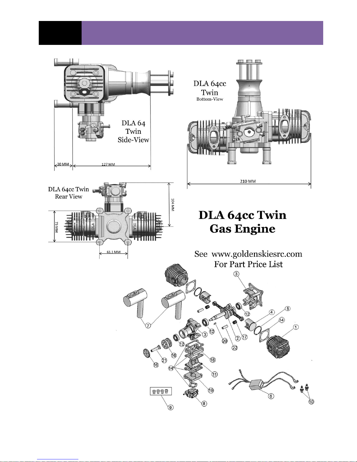
DIMENSIONS and PARTS DIAGRAM (Typical):
06/29/2016 Copyrighted Material
Owner’s Manual All Rights Reserved 03180-10000
Page - 32 DLA 32, 58, 64, 64-I2, 116, 116-I2 & 128cc, 180c, 232cc Rev. A.05.11

GS R/C
DLA ENGINE OPERATING-INSTRUCTION
MANUAL
DLA 32
Dwg
Key #
Part Description
03180-01105
1
Cylinder Head, 32 / 64 cc STRAIGHT PLUG Conf.
03180-01106
2
Crankshaft & Connecting Rod, 3cc
03180-01107
3
Crank Case, Front & Rear, 32cc
03180-01108
4
Piston, 32 / 64 / 128cc
03180-01109
5
Ring, Piston, 32 / 64 / 128cc
03180-01110
6
Ignition Module, Capacitive Discharge., 32cc
03180-01111
7
Muffler,Can - Std, 32cc
03180-01112
8
Carburetor, 32cc, Complete, Tillotson HU-34A, 32cc
03180-01113
9
Standoffs, Engine Mounting, & Bolts, 32cc
03180-01114
10
Spark Plug, Iridium, (All DLA Engines)
03180-01115
11
Reed Valve Assembly, Carburetor, 32cc
03180-01116
12
Bearing Set, Front & Rear, Crankshaft (FAG), 32cc
03180-01117
13
Sensor, Ignition, w/mounting screws, (ALL DLA Engines)
03180-01118
14
Gasket Set, Muffler, Carburetor, Head, 32cc
03180-01119
15
Bolt Set: Mounting, Muffler, Prop, 32cc
03180-01120
16
Hub, Propeller, Washer, Propeller, 32cc
03180-01121
17
Bearing Needle, Connecting-rod wrist-pin, 32 / 64cc, 12mm (IKO Bearing, Japan)
03180-01122
18
Wrist-Pin, Piston, Con-rod, 32 / 64cc
03180-01123
19
Puffer - Line, Carb to Reed Valve Assembly
03180-01124
20
Bushing-Spacer, Crankshaft, forward
03180-01125
21
Propeller Shaft, Crankshaft Extension, 32cc
03180-01126 22 Retainers, Piston Pin, 32cc
03180-01127 1S Cylinder Head, 32 / 64 cc SLANTED PLUG Conf.
03180-01128 5B
Rings, BOWMAN 32,64, 128cc
03180-01129 Rerserved
03180-01130 Gasket, Cylinder Head
03180-01131 Gasket, Carburetor, 32cc
03180-01132 Rerserved
03180-01133 Key, Woodruff, 32cc
03180-01134 Gasket, Muffler, 32cc
03180-01135 Prop Shaft, Extension, 32cc
03180-01136 Prop Washer, Only, 32cc
03180-01137 Prop-Hub (Only), 32cc
03180-01138 Bolts, Muffler, (All DLA Engines)
03180-01139 Reed Values, Only, 32cc
01380-01106
Muffler, Pitts Style, DLA 32cc
01380-01145 Air Fiflter, Velocity Stack, (All DLA Engines)
01380-01239
Tachometer, (All DLA Engines)
01380-01240
Gasket,MUFFLER< New Style, & Bolts / Lock washers, 32 / 64cccc
01380-01140 Carburetor Gasket & Diaphragm Kit (DG-11HU), for Tillotson HU-134A Carb, 32cc
01380-01141 Carburetor, Rer-build Kit Completes (RK-31HU) for Titllotson HU-134A Carb, 32cc
01380-01142
Muffler, CANISTER, Includes: Muffler, Header, and couples (1 each), 32 & 64cc
03180-01143
Gasket, Muffler, Paper (original) with Bolts and Lockwashers
Part Numbers - Engine Components
DLA 32cc PARTS LIST - Rev: A.06
06/29/2016 Copyrighted Material
Owner’s Manual All Rights Reserved 03180-10000
Page - 33 DLA 32, 58, 64, 64-I2, 116, 116-I2 & 128cc, 180c, 232cc Rev. A.05.11

GS R/C
DLA ENGINE OPERATING-INSTRUCTION
MANUAL
06/29/2016 Copyrighted Material
Owner’s Manual All Rights Reserved 03180-10000
Page - 34 DLA 32, 58, 64, 64-I2, 116, 116-I2 & 128cc, 180c, 232cc Rev. A.05.11

GS R/C
DLA ENGINE OPERATING-INSTRUCTION
MANUAL
DLA 58
Dwg
Key #
Part Description
03180-01205 1
Cylinder Head, 58cc, Straight Plug Config
03180-01206 2 Crankshaft & Connecting Rod, 58cc
03180-01207 3 Crank Case, Front & Rear, 58cc
03180-01208 4 Piston & Wrist Pin w /retainers, 58cc
03180-01209 5 Ring, Piston, 58cc
03180-01210 6 Ignition Module, 58cc, Capacitive Discharge.
03180-01211 7
Muffler, Std-CAN, 58cc
03180-01212 8 Carburetor, 58cc, Complete, Walbro WT-247
03180-01213 9 Standoffs, Engine Mounting, & Bolts, 58cc
03180-01214 10 Spark Plug, Iridium, all engines
03180-01215 11 Reed Valve Assembly, Carburetor, 58cc
03180-01216 12
Bearing Set, Front & Rear, Crankshaft, (FAG), 58cc
03180-01217 13 Sensor, Ignition, w/mounting screws
03180-01218 14 Gasket Set, Muffler, Carburetor, Head, 58cc
03180-01219 15 Bolt Set: Mounting, Muffler, Prop, 58cc
03180-01220 16 Hub, Propeller, Washer, Propeller, 58cc
03180-01221 17 Bearing Needle, Connecting-rod wrist-pin, 58c / 116cc / 232cc, 13mm
03180-01222 18 Wrist-Pin, Piston, , Con-rod, 58 / 116cc
03180-01223 19 Puffer - Line, Carb to Reed Valve Assembly
03180-01224 20 Bushing-Spacer, Crankshaft, forward
03180-01225 21 Propeller Shaft, Crankshaft Extension, 58cc
03180-01226 22 Retainers, Piston Pin
03180-01227 23
Reserved
03180-01228 5B
Rings, BOWMAN, 58cc / 116cc / 232cc
03180-01229 -- Reserved
03180-01230 -- Gasket, Cylinder Head, 58cc / 116cc / 232cc
03180-01231 -- Gasket, Carburetor, 58cc
03180-01232 -- Reserved
03180-01233 -- Key, Woodruff
03180-01234 -- Gasket, Muffler, 58cc / 116cc / 232cc
03180-01235 --
Reserved
03180-01236 --
Prop Washer, Only, 58cc
03180-01237 --
Prop-Hub (Only), 58cc
03180-01238 -- Bolts, Muffler, 500 x 0.8 - 16 mm, (2 ea)
01380-01144
--
Muffler, Pitts Style, 58cc
01380-01239 -- Tachometer
01380-01240 -- Diaphragm Repair Kit, WT-805
01380-01241 -- Gasket, New Style, & Bolts / Lock washers, 58cc
01380-01242 -- Repair Kit, Carburetor: WT-805
01380-01243 1S
Cylinder Head, 58cc, Slanted Spark Plug Configuration
03180-01245
Muffler, Canister, 58cc
DLA 58cc PARTS LIST - Rev: A.06
Part Numbers - Engine Components
PARTS LIST 58cc: (See www.goldenskiesrc.com for current lists and Prices)
06/29/2016 Copyrighted Material
Owner’s Manual All Rights Reserved 03180-10000
Page - 35 DLA 32, 58, 64, 64-I2, 116, 116-I2 & 128cc, 180c, 232cc Rev. A.05.11
GS R/C
DLA ENGINE OPERATING-INSTRUCTION
MANUAL
06/29/2016 Copyrighted Material
Owner’s Manual All Rights Reserved 03180-10000
Page - 36 DLA 32, 58, 64, 64-I2, 116, 116-I2 & 128cc, 180c, 232cc Rev. A.05.11

GS R/C
DLA ENGINE OPERATING-INSTRUCTION
MANUAL
DLA 64
Dwg
Key #
Part Description
03180-01105
1
Cylinder Head, 32 / 64 / 128cc, Straight SparkPlug Configuration
03180-01305
2
Crankshaft & Connecting Rod, 64cc Twin Boxer
03180-01306
3
Crank Case, Front & Rear, 64cc Twin Bboxer
03180-01108
4
Piston & Ring. 32 / 64 / 1 28cc
03180-01109
5
Ring, Piston, 32 / 64 / 128cc
03180-01309
6
Ignition Module, Capacitive Discharge., 64cc Twin Boox er
03180-01310
7
Muffler, 64cc Twin Boxer
03180-01311
8
Carburetor, 64cc, Complete, Walbro WT-805
03180-01312
9
Bolt-Set, Mount, Muffler, Prop.
03180-01114
10
Spark Plug, All Engines
03180-01314
11
Reed Valve Assembly, Carburetor, 64cc Twin Boxer
03180-01315
12
Bearing Set, Front, Middle & Rear, Crankshaft (FAG), 64cc Twin Boxer
03180-01316
13
Bolts, Muffler, All Engines
03180-01317
14
Gasket Set, Muffler, Carburetor, Head, 64cc
03180-01318
15
Standoffs, Engine Mounting, 64cc
03180-01319
16
Hub, Propeller, Washer, Propeller
03180-01320
17
Bearing Needle, Connecting-rod wrist-pin, 32 / 64cc, 12mm
03180-01321
18
Heat Block, Carburetor, 64cc
03180-01322
19
Mount - Spacer, Carburetor, 64cc
03180-01323
20
Key, Woodruff, 64c
03180-01324
21
Propeller Shaft, Crankshaft Extension, 32 / 64 / 128cc
03180-01325 Reserved
03180-01122
22
Wrist-Pin, Piston, , Con-rod, 32 / 64 / 128cc
03180-01327 Mounting Base-Ring
03180-01128
Rings, BOWMAN 32, 64, 128cc
03180-01329 Retainers, Piston Pin, (All Engines)
03180-01330
14
Gasket, Carburetor, 64cc
03180-01331 Gasket, Muffler, 32 / 64 / 128cc
03180-01130
14
Gasket, Cylinder Head, 32 / 64 / 128cc
03180-00117 Sensor, Ignition, w/mounting screws, All Engines
03180-01334 Reed Valve, Only, 32 / 64 / 128cc
03180-01335 Prop-Hub, 64cc
03180-01336
19
Base, Carburetor, 64cc
03180-01337 Prop Wash, Only
03180-01338 Plug, Sparkplug hole, All Engines.
03180-01339 Reserved
03180-01340
14
Gasket, Muffler, New Style, & Bolts / Lock washers, 64cc
03180-01341
1S
Cylinder Heads, Slanted Spark Plug Configuration.
03180-01342 Plugs, Spark Plug Holes, 32 / 64 / 128cc
01380-01142
Muffler, Canister, Includes: Muffler, Header, and coupler/clamps (1 each), 32 & 64cc
(2 required for 64cc)
01380-01239 Tachometer, (All DLA Engines)
DLA 64cc PARTS LIST - Rev: A.06
Part Numbers - Engine Components
(See www.goldenskiesrc.com for current lists and Prices)
06/29/2016 Copyrighted Material
Owner’s Manual All Rights Reserved 03180-10000
Page - 37 DLA 32, 58, 64, 64-I2, 116, 116-I2 & 128cc, 180c, 232cc Rev. A.05.11

GS R/C
DLA ENGINE OPERATING-INSTRUCTION
MANUAL
06/29/2016 Copyrighted Material
Owner’s Manual All Rights Reserved 03180-10000
Page - 38 DLA 32, 58, 64, 64-I2, 116, 116-I2 & 128cc, 180c, 232cc Rev. A.05.11

GS R/C
DLA ENGINE OPERATING-INSTRUCTION
MANUAL
DLA 116
Dwg
Key #
Part Description
03180-01404
1
Cylinder Head, 58cc / 116cc, Straight Plug Configuration
03180-00405
2
Crankshaft & Connecting Rod, 116cc
03180-01406
3
Crank Case, Front & Rear, 116cc
03180-01407
4
Piston, Wrist Pin & Retainers, 116cc (Piston Dia: 45.8 mm)
03180-01408
5
Ring, Piston (Factory), 58cc / 116cc
03180-01409
6
Ignition Module, Capacitive Discharge., 116cc
03180-01410
7
Muffler, CAN, each, 116cc
03180-01411 8
Carburetor, 116cc, Complete, Walbro WJ71 - 311
03180-01412
9
Bolt-Set, Mount, Muffler, Prop., 116cc
03180-01413
10
Spark Plug, (All DLA Engines)
03180-01414
11
Reed Valve Assembly, Carburetor, 16cc
03180-01415
12
Bearing Set, Front, Middle & Rear, Crankshaft, 116cc
03180-01416
13
Bolts, Muffler, (All DLA Engines)
03180-01417
14
Gasket Set, Muffler, Carburetor, Head, 116cc
03180-01418
15
Standoffs, Engine Mounting, 116cc
03180-01419
16
Hub, Propeller, Washer, Propeller, 116c
03180-01420
17
Bearing Needle, Connecting-rod wrist-pin, 58 / 116cc, 13mm
03180-01421
18
03180-01422
19
Fuel Line, Carb to Engine.
03180-01423
20
Bushing-Spacer, Crankshaft, forward
03180-01424
21
Propeller Shaft, Crankshaft Extension
03180-01425
22
Retainers, Piston Pin
03180-01426
23
Bushing-Spacer, Crankshaft, forward
03180-01427
24
Sensor, Ignition, w/mounting screws
03180-01428
03180-01429 Prop Wash, Only, 116cc
03180-01430 Gasket, Carburetor, 116cc
03180-01431 Gasket, Muffler, 58 / 116cc
03180-01432 Gasket, Cylinder Head, 58 / 116cc
03180-01433 Key, Woodruff, 116cc
03180-01434 Mount Base, Ring
03180-01435 Heat Block, Carburetor, 116cc
03180-01436 Base, Carburetor, 116cc
03180-01437
03180-01438 Bolt-Set, Mount, Muffler, Prop., 116cc
03180-01439 Reed Valve, Only, 116cc
03180-01440 Prop-Hub, Only, 116cc
03180-01441 Carburetor (WJ-71) Repair Kit: K10-WJ, 116cc
03180-01405 Air Filter, 90 deg, (All DLA Engines
03180-01406
Muffler, Cannister, 58 / 116cc
01380-01239 Tachometer, (All DLA Engines)
03180-01407 Diaphragm Repair Kits, Carb: WJ71, 116cc
03180-01442
Gaskets (2), Muffler (New Style), Bolts and Lockwashers, 58 / 116cc
03180-01443 Heat Shield Material, 50 sq-in
03180-01228
Rings, BOWMAN, 58 / 116cc
03180-01222
23
Wrist-Pin, Piston, , Con-rod, 58 / 116cc
01380-01243
1S
Cylinder Head, 58cc, Slanted Spark Plug Configuration
DLA 116cc PARTS LIST - Rev: A.06
Part Numbers - Engine Components
(See www.goldenskiesrc.com for current lists and Prices)
06/29/2016 Copyrighted Material
Owner’s Manual All Rights Reserved 03180-10000
Page - 39 DLA 32, 58, 64, 64-I2, 116, 116-I2 & 128cc, 180c, 232cc Rev. A.05.11

GS R/C
DLA ENGINE OPERATING-INSTRUCTION
MANUAL
CARBURETOR TUNING and CARE:
A tachometer is required for initial carburetor tuning and is a good idea for subsequent tuning.
Remember to never adjust the carburetor while the engine is running.
The carburetor’s high and low mixture valves have been preset at the factory; however, different
altitudes and climates may require minor adjustments. Turning the mixture adjustment-screws
clockwise, leans the mixture and turning the screws counter-clockwise richens the mixture. If
you get completely out tune, reset the mixture controls as follows:
1. High Adjust: Turn the Needle Valve Screw clockwise until it stops, then counter-
clockwise 1-1/2 to 1-3/4 turns.
2. Low Adjust: Turn the Needle Valve Screw clockwise until it stops, then start at 1-turn
counter-clockwise and advance to 1-1/4 (in 1/16 turns) as needed to start engine.
IMPORTANT: When turning either mixture adjustments clockwise to the stop point, take care
not to over tighten and destroy the value seat. A “TWO-FINGER” hold on the screw driver
provides a light touch and a reasonable feel for the stop point.
Adjust the High Mixture: (Clockwise leans the mix and increases the rpm. Counter-clockwise
richens the mix and generally decreases the rpm.)
1. Start the engine and measure the rpm.
2. Adjust the High mixture to achieve maximum rpm (engine stopped).
3. Turn High mixture counter-clockwise (richen) until the rpm drops to 100 to 2o0 rpm less
than the maximum rpm.
4. Return to idle, and idle for approximately sixty (60) seconds.
a. Be sure the idle rpm is constant and smooth.
b. If the idle is too rich, the rpm may slow until the engine stops.
i. Adjust accordingly.
5. Check the Low to High throttle transition, by somewhat rapidly moving the transmitters
throttle control from idle to maximum.
a. See “Trouble Shooting” if the transition is not smooth and responsive.
Adjusting the Mechanical “Idle” Screw:
1. The Mechanical Idle Adjustment Screw is simply a mechanical advancement or decrement
of the carburetor’s butterfly throttle.
2. Adjust to the Mechanical Adjustment Screw to the lowest idle that keeps the engine
running and does not cause any aircraft forward motion at idle rpm.
3. If you plan to stop the engine by completely closing the butterfly-throttle, then you will
need to remove the Mechanical Idle Adjustment Screw or back it out far enough to allow
the butterfly to completely close. Do not attempt to remove the spring that returns the
butterfly value to the low position.
NOTE: On the 116cc-I2 and the 128cc QUAD richen the high-needle on the rear cylinder/bank
carburetor by about 1/16 to 3/32 turns to help cool these cylinders, if they are running too hot; or
event more so, in the event of a particularly hot flying day.
06/29/2016 Copyrighted Material
Owner’s Manual All Rights Reserved 03180-10000
Page - 40 DLA 32, 58, 64, 64-I2, 116, 116-I2 & 128cc, 180c, 232cc Rev. A.05.11

GS R/C
DLA ENGINE OPERATING-INSTRUCTION
MANUAL
Engine
Carburetor Type
Diaphragm / Gasket
Kit
Repair Kit
32
Tillotson™, HU-134A
03180-00118
03180-RK-31HU
58
Walbro™, WT-247 Series
03180-00131
03180-00TBD
64
Walbro™, WT-805 Series
03180-00230
03180-K20-WAT
116
Walbro™, WJ-71 Series
03180-00330
03180-K10-WJ
116 I2
Walbro™
03180-00xx
TBD
128cc
Walbro™
03180-00xxx
TBD
DLA32cc Carb DLA 58cc Carb
DLA 64cc Carb DLA 116cc Carb
Carburetor Cleaning: The carburetor screen will need to be cleaned periodically. Clean the
screen with clean, fresh gasoline and blow off with compressed air. Also check the choke and
throttle butterfly for tightness.
Carburetor Repair Kits:
06/29/2016 Copyrighted Material
Owner’s Manual All Rights Reserved 03180-10000
Page - 41 DLA 32, 58, 64, 64-I2, 116, 116-I2 & 128cc, 180c, 232cc Rev. A.05.11

GS R/C
DLA ENGINE OPERATING-INSTRUCTION
MANUAL
TROUBLE SHOOTING GUIDE
ALWAYS STOP ENGINE WHEN MAKING ADJUSTMENTS
#
Problem / Symptom
Possible Solution
1
Engine is Flooded with fuel
1) Turn kill switch to OFF, Remove
Sparkplug. , Blow out and dry plug electrodes,
Turn engine to where the cylinder head is
pointed down, Drain Fuel, Rotate propeller
around several times, replace sparkplug and
restart engine
2
Engine starts after being choked but the
stops soon thereafter
1) The low mixture valve may be too lean.
Richen by turning counter-clockwise. Adjust the
Low End Mixture needle valve to achieve a
smooth idle and a reliable transition to high
throttle. Generally, if the engine stutters or
coughs in the mid range during low to high
transition or when the throttle is advanced, the
Low End needle is too lean and possibly the
High End Needle valve is too lean.
3
Engine runs rough and vibrates strongly
1) Check the propeller balance, 2) Balance
Propeller as needed, 3) Check engine to
firewall mounting bolts for security, 4) Check
tank to engine plumbing for air leaks, 5) Check
sparkplug for carbon build up (an indication
that gas:oil mix is too low or rich with oil) 6)
Check sparkplug gap, 7) Check all bolts for
tightness and security, 8) Make sure the engine
is not mounted in a bias, that is the crankcase is
being twisted by the mounting misalignment,
the ends of the stand-offs should be in the same
plane.
TROUBLE SHOOTING:
06/29/2016 Copyrighted Material
Owner’s Manual All Rights Reserved 03180-10000
Page - 42 DLA 32, 58, 64, 64-I2, 116, 116-I2 & 128cc, 180c, 232cc Rev. A.05.11

GS R/C
DLA ENGINE OPERATING-INSTRUCTION
MANUAL
4
Engine does not reach a "normal' high
rpm at full throttle
1) Check carburetor settings, particularly the
High End Mixture Needle Valve, 2) Check to
see that the propeller is NOT larger than
specified in the DLA engine specifications, 3)
Check for engine overheating … a sign that
gas:oil mix is to lean, that is too little oil, 4)
Check ignition timing, 5) Confirm you are using
the correct size muffler, 6) Verify proper gas:oil
mixture.
5
Engine hesitates or pauses when
throttle is transitioned from Low to
High (especially when throttle is
advanced rapidly)
1) Low End Mixture Needle Value is too Lean.
Open (Counterclockwise) ~ 1/16 to 1/8 turn at a
time and test again.
6
Idle rpm is not steady or smooth
1) Low End Mixture Needle Valve is too Rich,
2) Close (Clockwise) ~ 1/16 to 1/8 turn at a
time and test again.
7
Engine Stalls or stops at High or Full
Throttle
1) The High End Mixture Needle Valve is too
lean, 2) Open High Mix 1/16 to 1/8 turns and
test again.
06/29/2016 Copyrighted Material
Owner’s Manual All Rights Reserved 03180-10000
Page - 43 DLA 32, 58, 64, 64-I2, 116, 116-I2 & 128cc, 180c, 232cc Rev. A.05.11

GS R/C
DLA ENGINE OPERATING-INSTRUCTION
MANUAL
OIL and Oil:Gas Mixture Table
A table of Gasoline to Oil ratios has been provided for your use. (Appendix A) Another useful
source for determining the oil quantity to be added to a specified amount of gasoline can be found
at:
www.csgnetwork.com/oilfuelcalc.html
Precision measuring, mixing cups are available from: KAM-TECH, LLC, 2147 W. 236th
Street, Torrance, CA 90501, 310-257-1240; “Ratio Rite Measuring Cup”
There are multiple sources of high quality oil available. Several are listed below:
Band Type Typical Mix Ratio
AMSOIL Professional Saber Synthetic 40:1 to 45:1
www.amsoilc.om/shop/by-product/motor-oil/2-stroke/saberprofessional/?page=%2fstorefront%2fatp.aspx
Red Line (NOT TESTED)
Royal Purple (NOT TESTED) Synthetic 40:1 to 45:1
Bell Ray (Honda) (NOT TESTED)
Yamalube Tested Blend 45 : 1
Torco T-2R Tested Blend 40 : 1
Klotz, R50, Super X2 or BIA Grade (NOT TESTED), Synthetic 45 : 1
The above oils are not for break-in but for normal flying after the break-on
period.
06/29/2016 Copyrighted Material
Owner’s Manual All Rights Reserved 03180-10000
Page - 44 DLA 32, 58, 64, 64-I2, 116, 116-I2 & 128cc, 180c, 232cc Rev. A.05.11

GS R/C
DLA ENGINE OPERATING-INSTRUCTION
MANUAL
WARRANTY:
The DLA Manufacturer warrants DLA engines to be free of defects at the time of purchase. The
DLA 32cc, 58cc, 64cc and 116cc Gas Engines have a two (2) year limited warranty, from the date
of purchase, when purchased from a GOLDEN SKIES R/C AIRCRAFT, Inc. distribution retailer.
The DLA warranty is granted only to the original engine purchaser and is not transferable or
assignable. During the warranty period, GOLDEN SKIES R/C AIRCRAFT, Inc. will, at the
discretion of GOLDEN SKIES R/C AIRCRAFT, Inc., repair and/or replace engine parts that do not
meet original factory specifications. All DLA engines must be marked with a factory Serial
Number for the warranty to apply. The 116-I2 and 128cc QUAD retains a two (2) year warranty.
Warranty Extensions:
If the DLA engine is purchased through a GOLDEN SKIES R/C AIRCRAFT, Inc. authorized
retailer, a third (3
registration. The original purchaser must purchase the third (3rd) year of warrant directly
from GOLDEN SKIES R/C AIRCRAFT, Inc. when the purchaser registers the engine with
GOLDEN SKIES R/C AIRCRAFT, Inc. All terms and conditions of warranty registration
apply.
If the DLA engine is purchased directly from GOLDEN SKIES R/C AIRCRAFT, Inc., the
warranty period will be three (3) years. The 116-I2 and 128cc engines have a two (2) year
warranty.
Golden Skies R/C Aircraft, Inc. does not honor the warranty on any DLA engine(s) purchased from
outside the Golden Skies R/C Aircraft distribution channel. Upon request and authorization from
GOLDEN SKIES R/C AIRCRAFT, INC., DLA engines purchased outside the GOLDEN SKIES R/C
AIRCRAFT, INC. distribution channel may be serviced by GOLDEN SKIES R/C AIRCRAFT, INC.
The consumer will be charged the current retail cost of parts and the current, associated hourly
labor rate to repair the engine. All other terms and conditions specified by FeiaoModel and/or
Golden Skies R/C Aircraft herein apply to a DLA engine purchased outside the Golden Skies R/C
Aircraft distribution Channel.
Warranty Registration must occur with seven (7) days of the original purchase date.
The original purchaser must register the DLA engine with Golden Skies R/C Aircraft, and provide
the following:
Date and place of Purchase, copy of Sales Receipt.
Engine Serial Number.
Name, address, phone and E-mail address of Original Purchaser.
The Warranty does not cover any of the following:
Damage caused by:
06/29/2016 Copyrighted Material
Owner’s Manual All Rights Reserved 03180-10000
Page - 45 DLA 32, 58, 64, 64-I2, 116, 116-I2 & 128cc, 180c, 232cc Rev. A.05.11
rd
) year of warranty may be purchased for $40.oo at the time of warranty
o The purchaser assumes the responsibility of maintaining a current email address
with GOLDEN SKIES R/C AIRCRAFT, Inc.
o Improper Handling.
o Improper Operation.
o Disassembly, in any way, of the Engine or Carburetor System.
Disassembly will invalidate the warranty.
o Engine or Carburetor Modifications.
o Damage caused by trauma, impact or crashes

GS R/C
DLA ENGINE OPERATING-INSTRUCTION
MANUAL
o Damage caused by use of improper fuels or oils, or mixtures thereof.
87 or 89 Octane, unleaded gasoline is all that is allowed.
o Interior Rubber Carburetor parts are normal “Wear and Tear” parts.
NOTE: Gas / Alcohol mixtures or Alcohol additives to the gas are known
to accelerate deterioration of carburetor rubber parts.
o Damage caused by Fuel or Gas Additives other than what is described in
this operations manual.
o Damage cause by improper ignition battery selection.
o Damage incurred during transit to or from the repair facility.
o Stripped or cross-threading bolts or spark-plug(s).
o Damage as a result of improper electrical wiring connections.
o Damage caused by overheating the engine.
o Tune-ups, including the sparkplug(s).
Any other use of the DLA engine(s) for purposes other than powering a Model
Aircraft will void the warranty.
Shipping Charges to and return from the GS R/C service center
HOW TO OBTAIN WARRANTY SERVICE:
1. Contact GS R/C for an authorization warranty return case-number.
2. Return the following to GS R/C:
a. Engine
b. Muffler(s)
c. Sparkplug(s)
d. Ignition
3. Ship the items listed in #2 above to: (GS R/C is not responsible for shipment loss or
shipment damage.)
Golden Skies R/C Aircraft, Inc.
Service Dept.
30882 Rivera Place
Laguna Niguel, CA 92677
4. Insure the Engine for the purchase Price or as follows whichever is more:
a. DLA 32cc Engine $ 300.00
b. DLA 58cc Engine $ 400.00
c. DLA 64cc Engine $ 550.00
d. DLA 116cc Engine $ 700.00
e. DLA 116cc I2 Engine $1,399.00
f. DLA 128cc QUAD $ 849.00
5. Include a typed and signed explanation of the engines problem(s)
6. The GOLDEN SKIES R/C AIRCRAFT, INC. Service Department will respond with a
written estimate for labor charges.
7. Damaged parts or parts that do not meet factory specification will not be return to the
sender.
8. Provide full purchaser information: Name, address, phone #, email address.
06/29/2016 Copyrighted Material
Owner’s Manual All Rights Reserved 03180-10000
Page - 46 DLA 32, 58, 64, 64-I2, 116, 116-I2 & 128cc, 180c, 232cc Rev. A.05.11
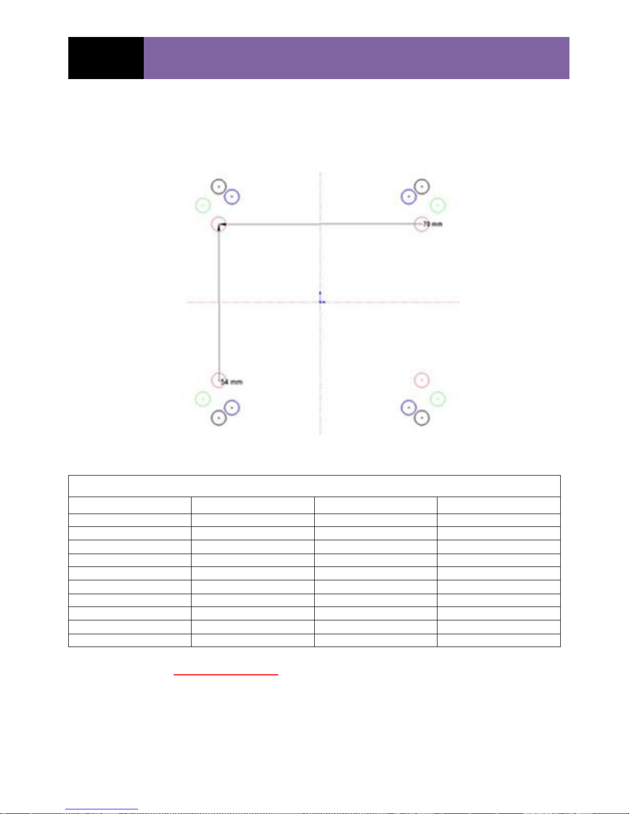
GS R/C
DLA ENGINE OPERATING-INSTRUCTION
MANUAL
Table 1
Engine
Template Hole Color
X
c/c
– Dimension
Y
c/c
- Dimension
32 cc
Red
70 mm (2.75”)
54 mm (2.13”)
58 cc
Green
76 mm (2.99”)
63.5 mm(2.50”)
64 cc (Twin Boxer)
Blue
61 mm (2.40”)
73 mm (2.87)
64-I2 (inline)
78 mm (3.07”)
65 mm (2.56”)
116 cc (Twin Boxer)
Black
70 mm (2.75”)
80 mm (3.15”)
116-I2cc (inline)
---
70 mm (2.75”)
80 mm (3.15”)
128cc (QUAD)
---
70 mm (2.75”)
80 mm (3.15”)
180cc
---
80 mm (3.15”)
90 mm (3.54”)
232cc (Quad)
--- ---
Dimensioned Mounting Template (paper)
Always verify (Measure) the above paper template, Mounting
Diagram Dimensions.
06/29/2016 Copyrighted Material
Owner’s Manual All Rights Reserved 03180-10000
Page - 47 DLA 32, 58, 64, 64-I2, 116, 116-I2 & 128cc, 180c, 232cc Rev. A.05.11

GS R/C
DLA ENGINE OPERATING-INSTRUCTION
MANUAL
Table 2 - DLA Published Specifications
DLA 32cc (1.97 in3) Gas Engine
Power: 3.8 HP @ 8200 rpm
Idle Speed: 1,350 - 1,700 rpm
Static Thrust: 19.4 pounds @ 100 m (~328 ft) (Pulling Force)
17.2 pounds @ 1,800 m (~5,900 ft)
Propellers: 18 x 8 / 10, 19 x 8, 20 x 8
Carburetor: Tillotson™, HU-134A
CDI Voltage: 6.4 – 8.4 VDC
Spark Plug: CM-6 Special, Iridium
Exhaust Volume: 32.23 cc (1.97 in3)
Cylinder Diameter / Stroke: 37 mm / 30 mm (1.46 in / 1.18”)
Compression Ratio: 7.6 : 1
Gas : Oil Ratios: 25 – 30 : 1 Break-in Trial Run; 40 – 50 : 1 Normal Flying
Weights: Engine 32.1 oz, Muffler: 2.3 oz, Ignition 3.5 oz
DLA 58cc (3.54 in3) Gas Engine
Power: 6.0 @ HP @ 8500 rpm
Idle Speed: 1,400 -1,500 rpm
Static Thrust: 33.1 pounds @ 100 m (~328 ft) (Pulling Force)
29.1 pounds @ 1,800 m (~5,900 ft)
Propellers: 22 x 10, 23 x 8/10, 24 x 8
Carburetor: Walbro™, “WT-xxx” Series
Spark Plug: CM-6 Special, Iridium
CDI Voltage: 6.4 – 8.4 VDC
Exhaust Volume: 58 cc (3.54 in3)
Cylinder Diameter / Stroke: 46 mm / 35 mm (1.77 in / 1.38”)
Compression Ratio: 7.8 : 1
Gas : Oil Ratios: 25 – 30 : 1 Break-in Trial Run; 40 – 50 : 1 Normal Flying
Weights: Engine 49.1 oz, Muffler: 3.87 oz, Ignition 4.76 oz
DLA 64cc (3.91 in3) Gas Engine (Twin Boxer)
Power: 7.2 @ HP @ 8500 rpm
Idle Speed: 1,400 rpm
Static Thrust: 34.4 pounds @ 100 m (~328 ft) (Pulling Force)
30.4 pounds @ 1,800 m (~5,900 ft)
Propellers: 22 x 10, 23 x 8/10, 24 x 8
Carburetor: Walbro™. “WT-xxx” Series
CDI Voltage: 6.4 – 8.4 VDC
Spark Plug: CM-6 Special, Iridium
Exhaust Volume: 64 cc (3.97 in3)
Cylinder Diameter / Stroke: 37 mm / 30 mm (1.46 in / 1.18”)
Compression Ratio: 7.8 : 1
Gas : Oil Ratios: 25 - 30 : 1 Break-in Trial Run; 40 – 50 : 1 Normal Flying
Weights: Engine 57.1 oz, Muffler: 2.3 x 2 ea oz, Ignition 4.76 oz
DLA 64-I2cc (3.91 in3) Gas Engine (In-Line)
Power: 7.6 @ HP @ 8500 rpm
Idle Speed: 1,400 rpm
Static Thrust: 35 pounds @ 100 m (~328 ft) (Pulling Force)
31 pounds @ 1,800 m (~5,900 ft)
Propellers: 22 x 10, 23 x 8/10, 24 x 8
Carburetor: Walbro™. “WT-xxx” Series
CDI Voltage: 6.4 – 8.4 VDC
Spark Plug: CM-6 Special, Iridium
Exhaust Volume: 64 cc (3.97 in3)
Cylinder Diameter / Stroke: 37 mm / 30 mm (1.46 in / 1.18”)
06/29/2016 Copyrighted Material
Owner’s Manual All Rights Reserved 03180-10000
Page - 48 DLA 32, 58, 64, 64-I2, 116, 116-I2 & 128cc, 180c, 232cc Rev. A.05.11

GS R/C
DLA ENGINE OPERATING-INSTRUCTION
MANUAL
Compression Ratio: 7.8 : 1
Gas : Oil Ratios: 25 - 30 : 1 Break-in Trial Run; 40 – 50 : 1 Normal Flying
Weights: Engine 77 oz, Muffler: 4 oz, Ignition 9.2 oz
DLA 116cc (7.08 in3) Gas Engine (Twin Boxer)
Power: 11.8 HP @ 7500 rpm
Idle Speed: 1,300 rpm
Static Thrust: 59.9 pounds @ 100 m (~328 ft) (Pulling Force)
52.5 pounds @ 1800 m (~5,900 ft)
Propellers: 26 x 10/12, 27 x 10, 28 x 10
Carburetor: Walbro™, “WJ-xx” Series
CDI Voltage: 6.4 – 8.4 VDC
Spark Plug: CM-6 Special, Iridium
Exhaust Volume: 116 cc (7.08 in3)
Cylinder Diameter / Stroke: 46 mm / 35 mm (1.77 in / 1.38”)
Compression Ratio: 7.8 : 1
Gas : Oil Ratios: 25 – 30 : 1 Break-in Trial Run; 40 – 50 : 1 Normal Flying
Weights: Engine 88.8 oz, Muffler: 4.05 x 2 ea oz, Ignition 6.34 oz
DLA 116cc I2 (7.08 in3) Gas Engine (In-Line)
Power: 12.8 HP @ 7500 rpm
Idle Speed: 1,200 rpm
Static Thrust: 61.8 pounds @ 100 m (~328 ft) (Pulling Force)
55.1 pounds @ 1800 m (~5,900 ft)
Propellers: 27 x 10/12, 28 x 10, 29 x 10
Carburetor: Walbro™, “WJ-” Series
CDI Voltage: 6.4 – 8.4 VDC
Spark Plug: CM-6, Iridium Special
Exhaust Volume: 116 cc (7.08 in3)
Cylinder Diameter / Stroke: 46 mm / 35 mm (1.77 in / 1.38”)
Compression Ratio: 7.8 : 1
Gas : Oil Ratios: 25 – 30 : 1 Break-in Trial Run; 40 – 50 : 1 Normal Flying
Weights: Engine: 102.3 oz (6.39 lbs), Muffler: 12.3 oz, Ignition: 6.34 oz
DLA 128cc (7.81 in3) Gas Engine
Power: 13.0 HP @ 7500 rpm
Idle Speed: 1,250 rpm
Static Thrust: 62.0 pounds @ 100 m (~328 ft) (Pulling Force)
56.8 pounds @ 1,800 m (~5,900 ft)
Propellers: 27 x 10/12, 28 x 8/10, 29 x 10
Carburetor: Walbro™, “WT-xxx” Series
CDI Voltage: 6.4 – 8.4 VDC
Spark Plug: CM-6 Special, Iridium
Exhaust Volume: 128 cc (7.81 in3)
Cylinder Diameter / Stroke: 37 mm / 30 mm (1.46 in / 1.18”)
Compression Ratio: 7.8 : 1
Gas : Oil Ratios: 25 – 30 : 1 Break-in Trial Run; 40 – 50 : 1 Normal Flying
Weights: Engine: 120 oz (7.49 lbs), Muffler: 9.57 x 2 ea oz, Ignition 12.6oz
DLA 180cc (10.98 in3) Gas Engine
Power: > 18 HP @ 7,500 rpm
Idle Speed: 1,000 -1,250 rpm
Static Thrust: > 90 pounds @ 100 m (~328 ft) (Pulling Force)
> 81 pounds @ 1,800 m (~5,900 ft)
Propellers: 32 x 10 / 12 / 14, 33 x 10
06/29/2016 Copyrighted Material
Owner’s Manual All Rights Reserved 03180-10000
Page - 49 DLA 32, 58, 64, 64-I2, 116, 116-I2 & 128cc, 180c, 232cc Rev. A.05.11

GS R/C
DLA ENGINE OPERATING-INSTRUCTION
MANUAL
DLA 32 DLA 56 / 58 DLA 64 DLA 112 / 116 DLA 128cc
Prop-Bolts 40 62 62 80 80
Prop-Shaft Extension 257 296 301 301 301
Crank-Case Bolts 80 106 124 124 124
Spark Plug 90 90 90 90 90
Head / Cylinder Bolts 80 106 97 106 97
Carburetor Bolts 53 62 62 62 62
Muffler Bolts
Engine Mounting
Spark Plug Gap 0.18" 0.18" 0.18" 0.18" 0.18"
Ignition Sensor
Advance (Degrees)
~30⁰ ~30⁰ ~30⁰ ~30⁰ ~30⁰
Other
DLA Engines Bolt TORQUES (inch * lbs)
Carburetor: Walbro™, “WT-xxx” Series
CDI Voltage: 6.4 – 8.4 VDC
Spark Plug: CM-6 Special, Iridium
Exhaust Volume: 180 cc (10.98 in3)
Cylinder Diameter / Stroke: mm / mm (in /in)
Compression Ratio: 7.8 : 1
Gas : Oil Ratios: 25 – 30 : 1 Break-in Trial Run; 40 – 50 : 1 Normal Flying
Weights: Engine: 129.0 oz (8.1 lbs); Muffler: oz; Ignition: oz
DLA 232cc (14.6 in3) Gas Engine
Power: > 23 HP @ 7,500 rpm
Idle Speed: ~ 1,150 rpm
Static Thrust: >100 pounds @ 100 m (~328 ft) (Pulling Force)
> 90 pounds @ 1,800 m (~5,900 ft)
Propellers: 34 x 10, 35 x 10/12, 36 x 10 2-Blade, 28x14, 30x12, 32x12 3-Blade
Carburetor: Walbro™, “WT-xxx” Series
CDI Voltage: 6.4 – 8.4 VDC
Spark Plug: CM-6 Special, Iridium
Exhaust Volume: 232 cc (14.6 in3)
Cylinder Diameter / Stroke: mm / mm (in /in)
Compression Ratio: 7.8 : 1
Gas : Oil Ratios: 25 – 30 : 1 Break-in Trial Run; 40 – 50 : 1 Normal Flying
Weights: Engine: 172.8 oz; Muffler: 15.8 oz; Ignition: 15.2 oz
Engine Bolt Torques:
06/29/2016 Copyrighted Material
Owner’s Manual All Rights Reserved 03180-10000
Page - 50 DLA 32, 58, 64, 64-I2, 116, 116-I2 & 128cc, 180c, 232cc Rev. A.05.11

GS R/C
DLA ENGINE OPERATING-INSTRUCTION
MANUAL
oz ml oz ml oz ml oz ml oz ml oz ml
0.25 1.1 31.5 1.00 29.6 0.91 27.0 0.80 23.7 0.71 21.0 0.64 18.9
0.50 2.1 63.1 2.00 59.1 1.83 54.1 1.60 47.3 1.42 42.1 1.28 37.9
0.75 3.2 94.6 3.00 88.7 2.74 81.1 2.40 71.0 2.13 63.1 1.92 56.8
1.00 4.3 126.2 4.00 118.3 3.66 108.2 3.20 94.6 2.84 84.1 2.56 75.7
1.25 5.3 157.7 5.00 147.9 4.57 135.2 4.00 118.3 3.56 105.1 3.20 94.6
1.50 6.4 189.3 6.00 177.4 5.49 162.2 4.80 141.9 4.27 126.2 3.84 113.6
1.75 7.5 220.8 7.00 207.0 6.40 189.3 5.60 165.6 4.98 147.2 4.48 132.5
2.00 8.5 252.4 8.00 236.6 7.31 216.3 6.40 189.3 5.69 168.2 5.12 151.4
2.25 9.6 283.9 9.00 266.2 8.23 243.3 7.20 212.9 6.40 189.3 5.76 170.3
2.50 10.7 315.4 10.00 295.7 9.14 270.4 8.00 236.6 7.11 210.3 6.40 189.3
2.75 11.7 347.0 11.00 325.3 10.06 297.4 8.80 260.2 7.82 231.3 7.04 208.2
3.00 12.8 378.5 12.00 354.9 10.97 324.5 9.60 283.9 8.53 252.4 7.68 227.1
3.25 13.9 410.1 13.00 384.4 11.89 351.5 10.40 307.6 9.24 273.4 8.32 246.0
3.50 14.9 441.6 14.00 414.0 12.80 378.5 11.20 331.2 9.96 294.4 8.96 265.0
3.75 16.0 473.2 15.00 443.6 13.71 405.6 12.00 354.9 10.67 315.4 9.60 283.9
4.00 17.1 504.7 16.00 473.2 14.63 432.6 12.80 378.5 11.38 336.5 10.24 302.8
4.25 18.1 536.3 17.00 502.7 15.54 459.6 13.60 402.2 12.09 357.5 10.88 321.8
4.50 19.2 567.8 18.00 532.3 16.46 486.7 14.40 425.8 12.80 378.5 11.52 340.7
4.75 20.3 599.3 19.00 561.9 17.37 513.7 15.20 449.5 13.51 399.6 12.16 359.6
5.00 21.3 630.9 20.00 591.5 18.29 540.8 16.00 473.2 14.22 420.6 12.80 378.5
5.25 22.4 662.4 21.00 621.0 19.20 567.8 16.80 496.8 14.93 441.6 13.44 397.5
5.50 23.5 694.0 22.00 650.6 20.11 594.8 17.60 520.5 15.64 462.6 14.08 416.4
5.75 24.5 725.5 23.00 680.2 21.03 621.9 18.40 544.1 16.36 483.7 14.72 435.3
6.00 25.6 757.1 24.00 709.7 21.94 648.9 19.20 567.8 17.07 504.7 15.36 454.2
6.25 26.7 788.6 25.00 739.3 22.86 675.9 20.00 591.5 17.78 525.7 16.00 473.2
6.50 27.7 820.1 26.00 768.9 23.77 703.0 20.80 615.1 18.49 546.8 16.64 492.1
6.75 28.8 851.7 27.00 798.5 24.69 730.0 21.60 638.8 19.20 567.8 17.28 511.0
7.00 29.9 883.2 28.00 828.0 25.60 757.1 22.40 662.4 19.91 588.8 17.92 529.9
7.25 30.9 914.8 29.00 857.6 26.51 784.1 23.20 686.1 20.62 609.9 18.56 548.9
7.50 32.0 946.3 30.00 887.2 27.43 811.1 24.00 709.7 21.33 630.9 19.20 567.8
7.75 33.1 977.9 31.00 916.8 28.34 838.2 24.80 733.4 22.04 651.9 19.84 586.7
8.00 34.1 1009.4 32.00 946.3 29.26 865.2 25.60 757.1 22.76 672.9 20.48 605.6
8.25 35.2 1041.0 33.00 975.9 30.17 892.2 26.40 780.7 23.47 694.0 21.12 624.6
8.50 36.3 1072.5 34.00 1005.5 31.09 919.3 27.20 804.4 24.18 715.0 21.76 643.5
8.75 37.3 1104.0 35.00 1035.0 32.00 946.3 28.00 828.0 24.89 736.0 22.40 662.4
9.00 38.4 1135.6 36.00 1064.6 32.91 973.4 28.80 851.7 25.60 757.1 23.04 681.4
9.25 39.5 1167.1 37.00 1094.2 33.83 1000.4 29.60 875.4 26.31 778.1 23.68 700.3
9.50 40.5 1198.7 38.00 1123.8 34.74 1027.4 30.40 899.0 27.02 799.1 24.32 719.2
9.75 41.6 1230.2 39.00 1153.3 35.66 1054.5 31.20 922.7 27.73 820.1 24.96 738.1
10.00 42.7 1261.8 40.00 1182.9 36.57 1081.5 32.00 946.3 28.44 841.2 25.60 757.1
50 : 1
Appendix A
RATIOS
Normal Flying Ratios
Break-in Ratios
DLA Engine Gas and Oil Mixture Table
Gas
Volume to
be Mixed
(Gallons)
30 : 1
32 : 1
35 : 1
40 : 1
45 : 1
06/29/2016 Copyrighted Material
Owner’s Manual All Rights Reserved 03180-10000
Page - 51 DLA 32, 58, 64, 64-I2, 116, 116-I2 & 128cc, 180c, 232cc Rev. A.05.11
 Loading...