

Page 1
®
12V
DC
24V
DC
1
2
DRY LOCATION
CLICKTIGHT® PRO
SAFETY & WARNINGS
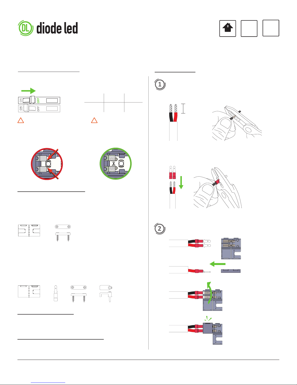
MAIN POWER MUST BE TURNED
OFF BEFORE INSTALLATION.
! !
FOR BLAZE LED TAPE LIGHT
INCORRECT - DO NOT ALLOW
CLICKTIGHT PRONGS TO TOUCH
LED CHIP CONTACTS WHEN LED
TAPE IS INSERTED.
SUPPLIED ACCESSORIES
DO NOT EXCEED CLASS 2 LIMIT
WHEN LOADING CLICKTIGHT.
CORRECT - CUT TAPE LIGHT SO
FOUR CONTACT/SOLDER POINTS
REMAIN TO ALLOW FOR GAP
BETWEEN PRONGS AND LED.
12VDC 60W 5A
24VDC 100W 4.17A
INSTALLATION GUIDE
INSTALLATION
PREPARE WIRE AND ATTACH SPADE CONNECTORS.
a. Determine wire gauge (22 - 18AWG). Strip wires.
3/8 in.
(10 mm)
b. Aach spade connectors with crimper tool.
Fit in crimper tool
notch. Squeeze to
secure wire.
Tape-To-Tape Kit: DI-CKTP-TTT-5
A. CLICKTIGHT PRO Tape-To-Tape Connector (5)
B. Tape Light Fastener (10) & Screws (20)
A. B.
Tape-To-Wire Kit: DI-CKTP-TTW-10
A. CLICKTIGHT PRO Tape-To-Wire Connector (10)
B. Spade Connector - 22AWG - 18AWG (25)
C. Tape Light Fastener (10) & Screws (20)
D. Wire Fastener (10) & Nails (10)
A. B. C.
D.
TOOLS FOR INSTALL
• Small Phillips-head screwdriver
• Wire Stripper / Crimper
• Scissors
• Hammer
COMPATIBLE LED TAPE LIGHTS
CLICKTIGHT PRO is compable with most Diode LED solid color
2-channel 12V and 24V tape lights. See product page for a full list.
ATTACH WIRE TO CLICKTIGHT
CLICKTIGHT® PRO INSTALLATION GUIDE
1 OF 2
IG121815-3.0
Page 2
−
−
INSTALLATION CONT.
5
7
3
4
6
8
a
b
+
−
+
−
+
−
1
2
®
+
−
®
+
−
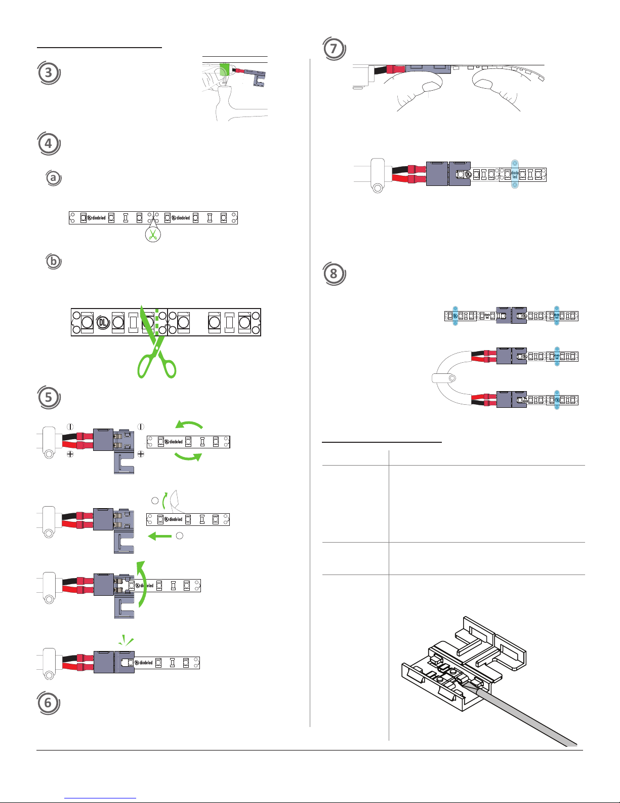
FASTEN WIRE TO SURFACE.
Place wire fastener around
wire and hammer into place.
CHOOSE OPTION (a) OR (b) FOR CUTTING
INSTRUCTIONS.
Applies to AVENUE 24™, FLUID VIEW®, VALENT®, VALENT®
HD, and ULTRA BLAZE™ tape lights.
Cut at the line indicated with scissors icon.
+
Applies only to BLAZE™ tape light:
DO NOT cut at scissors icon. Instead, cut tape light along outside
edge of LED chip closest to scissors icon so four contact/solder
points remain intact to tape light.
−
+
®
MOUNT TAPE LIGHT TO SURFACE.
Prep surface to remove dust and dirt. Adhere to a smooth,
nished, dry surface.
−
®
+
®
+
Ulize included Tape Light Fastener to secure tape to surface.
Fasten with small screwdriver.
DO NOT PLACE FASTENER ON LED CHIPS OR RESISTORS!
ADD TAPE-TO-TAPE CONNECTORS AND/OR
BENDING EXTENSIONS.
−
−
+
+
−
+
TAPE-TO-TAPE
CONNECTOR
®
®
ATTACH TAPE LIGHT TO CLICKTIGHT.
−
+
Determine orientaon of
tape light for correct polarity.
−
+
−
+
®
1
®
2
Insert strip under
metal contacts.
®
BENDING EXTENSION
(2x TAPE-TO-WIRE
CONNECTORS)
TROUBLESHOOTING
Symptom Common Cause
Fixture does not
illuminate
Fixture ickers
randomly, may
shut o
Fixture will
not insert into
CLICKTIGHT
• Incorrect wiring. Polarity of Low Voltage V+ and V- are
reversed. Check connecon at every CLICKTIGHT to
ensure polarity is not reversed.
• Circuit breaker is OFF or tripped.
• Incorrect voltage pairing of dimmer and xture. 12 V
dimmer models will not power a xture with a higher
voltage rang.
• Connecon is not secure. Check connecon at crimp,
at metal prongs of CLICKTIGHT and at any other
connecons.
• If tape light does not t under CLICKTIGHT prongs due
to ghtness, gently slide a 1/8” at head screwdriver
under prongs (shown below). Once both prongs are
loosened, proceed to slide tape light under prongs.
−
®
+
®
+
−
−
+
®
TEST CONNECTION.
Prior to mounng, turn on power and test connecon to
ensure system is operang properly. Turn o power again
before mounng.
CLICKTIGHT® PRO INSTALLATION GUIDE
2 OF 2
IG121815-3.0
 Loading...