

DKS Enterprises 9100 User Manual

Owner’s Manual
Model 9100
Vehicular Slide Gate Operator
DoorKing, Inc.
120 Glasgow Avenue
Inglewood, California 90301
U.S.A.
Phone: 310-645-0023
Fax: 310-641-1586
www.doorking.com
P/N 9100-065 REV B, 1/01
Copyright 2000 DoorKing, Inc. All rights reserved.

ii

Use this manual with the following model only.
Model 9100-080 with circuit board 4602-010.
DoorKing, Inc. reserves the right to make changes in the products described in this manual
without notice and without obligation of DoorKing, Inc. to notify any persons of any such revisions
or changes. Additionally, DoorKing, Inc. makes no representations or warranties with respect to
this manual. This manual is copyrighted, all rights reserved. No portion of this manual may be
copied, reproduced, translated, or reduced to any electronic medium without prior written consent
from DoorKing, Inc.
iii
IMPORTANT NOTICES
Vehicular gate systems provide convenience to their users and limit vehicular traffic onto your
property. These systems can produce high levels of force; therefore it is important that you are aware
of possible hazards associated with your gate operating system. These hazards may include pinch
points, entrapment, absence of controlled pedestrian access or traffic backup.
Be sure that the installer has instructed you on the proper operation of the gate and gate operator
system. Be sure that the installer has trained you about the basic functions of the required reversing
systems associated with your gate operating system and how to test them. These include reversing
loops, inherent reversing system, electric edges, photoelectric cells, or other external devices.
• This Owner's Manual is your property. Keep it in a safe place for future reference.
• Loops and loop detectors must be installed with this gate operator to prevent the gate from
closing on vehicular traffic.
• The speed limit for vehicular traffic through the gate area is 5 MPH. Install speed bumps and
signs to keep vehicular traffic from speeding through the gate area. Failure to adhere to
posted speed limits can result in damage to the gate, gate operator, and to the vehicle.
• Be sure that all residents are familiar with the proper use of the gate and gate operator. Be
sure that all residents are familiar with the possible hazards associated with the gate system.
• Be sure that all warning signs are permanently installed on both sides of the gate in an area
where they are fully visible to traffic.
• It is your responsibility to periodically check all reversing devices. If any of these devices are
observed to function improperly, remove the operator from service immediately and contact
your installing or servicing dealer.
• Follow the recommended maintenance schedule.
• Do not allow children to play in the area of the operator or to play with any gate-operating
device.
• Be sure that all activating devices are installed a minimum distance of 10 feet away from the
gate and gate operator, or in such a way that a person cannot touch the gate or gate operator
while using the activating device. If activating devices are installed in violation of these
restrictions, immediately remove the gate operator from service and contact your installing
dealer.
• To remove the gate operator from service, operate the gate to the full open position and then
shut off power to the operator at the service panel.
SPEED BUMP
HAZARD AREA
HAZARD AREA
VEHICULAR
SPEED BUMP
iv
TRAFFIC
PEDESTRAINS

IMPORTANT SAFETY INSTRUCTIONS
WARNING - To reduce the risk of injury or death:
1. READ AND FOLLOW ALL INSTRUCTIONS.
2. Never let children operate or play with gate controls. Keep the remote control
away from children.
3. Always keep people and objects away from gate. NO ONE SHOULD CROSS
THE PATH OF THE MOVING GATE.
4. Test the operator monthly. The gate MUST reverse on contact with a rigid object
or stop or reverse when an object activates the non-contact sensors. After
adjusting the force or the limit of travel, retest the gate operator. Failure to adjust
and retest the gate operator properly can increase the risk of injury or death.
5. KEEP GATES PROPERLY MAINTAINED. Read the owner's manual. Have a
qualified service person make repairs to gate hardware.
6. The entrance is for vehicles only. Pedestrians must use separate entrance.
7. SAVE THESE INSTRUCTIONS!
v
RESTRICTIONS AND WARNINGS
Install The Gate Operator Only If:
• The operator is appropriate for the usage Class of the application and the gate is within the
weight and length limitations specified for the operator.
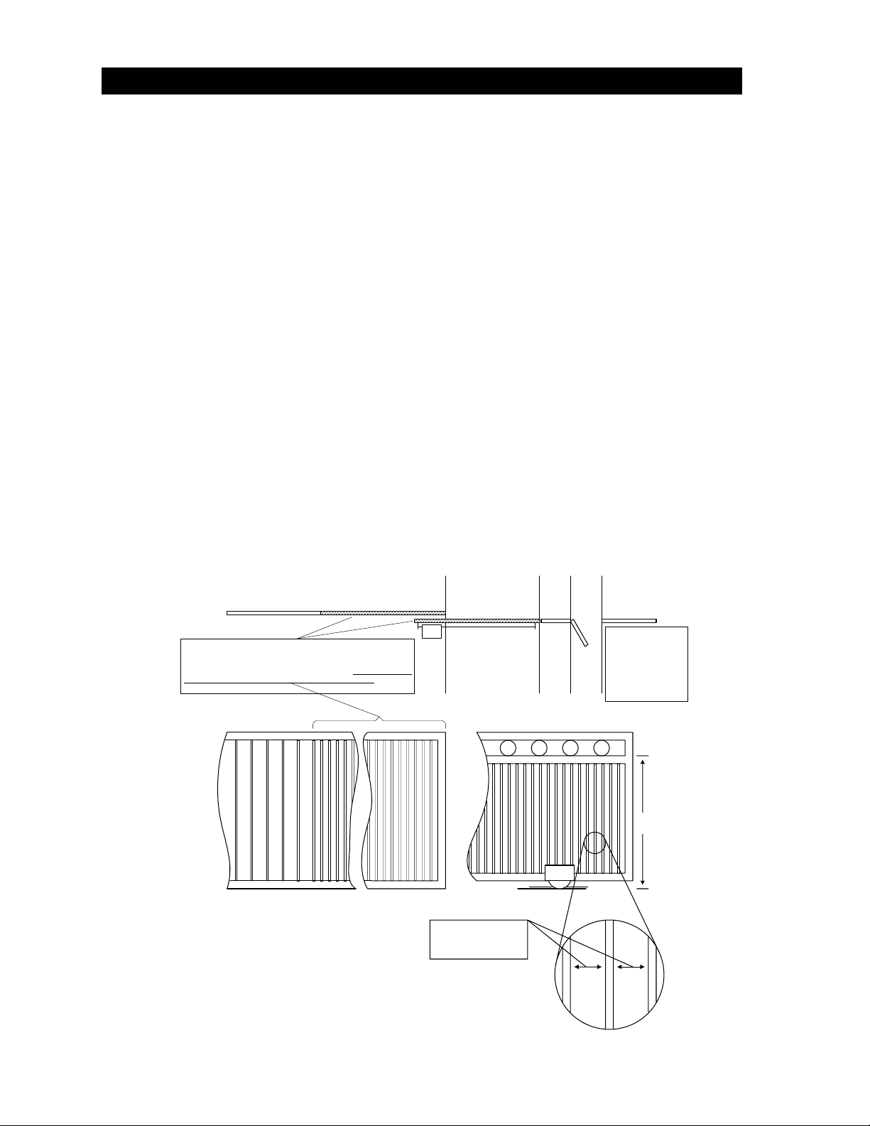
• All openings of a horizontal slide gate are guarded or screened from the bottom of the gate to
a minimum of 4 feet (1.2 m) above the ground to prevent a 2 ¼ inch (57.15 mm) diameter
sphere from passing through the openings anywhere in the gate, and in that portion of the
adjacent fence that the gate covers in the open position.
• All exposed pinch points are eliminated or guarded.
• This operator is intended for installation only on slide gates used to control vehicular traffic.
Pedestrians must be provided with a separate access opening.
• The gate must be installed in a location so that sufficient clearance is provided between the
gate and adjacent structures when opening and closing to reduce the risk of entrapment (see
diagram). Sliding gates should not open into public access areas.
• The gate must be properly installed and work freely in both directions prior to the installation
of the gate operator. Do not over-tighten the operator clutch to compensate for a damaged
gate.
• Controls must be far enough from the gate so that the user is prevented from coming in
contact with the gate while operating the controls. Outdoor or easily accessible controls
should have a security feature to prevent unauthorized use.
• All warning signs and placards must be installed where visible in the area of the gate.
Fence
All openings of a horizontal slide gate are guarded or screened from the
bottom of the gate to a minimum of four (4) feet (1.2 m) above the
ground to prevent a 2 1/4 inch (57.15 mm) diameter sphere from passing
through the openings anywhere in the gate and in that portion of the
adjacent fence that the gate c overs in the open position. (ref. UL325
51.8.4.a.2)
Fence
Vehicular Gate
Gate Operator
Spacing must be such
that a 2 1/4 inch sphere
cannot pass through.
Roadway
Gate
V-Track
Fence
Pedestrian
Access
The operator is
intended for installation
only on gates used for
vehicles. Pedestrians
must be supplied with a
seperate access
opening. (ref. UL325
Sidewalk
51.8.4.b)
4 ft.
min
vi
ENTRAPMENT PROTECTION
This vehicular gate operator is equipped with an inherent (Type A) entrapment sensing system. This
system will sense an obstruction in both the opening and closing gate cycles, and will cause the gate
to reverse direction should an obstruction be encountered. If the system detects a second obstruction
before reaching the full open or close limit after the initial reversal, an alarm will activate and the
operator will require a reset before resuming normal operation. See Section 4 for more information.
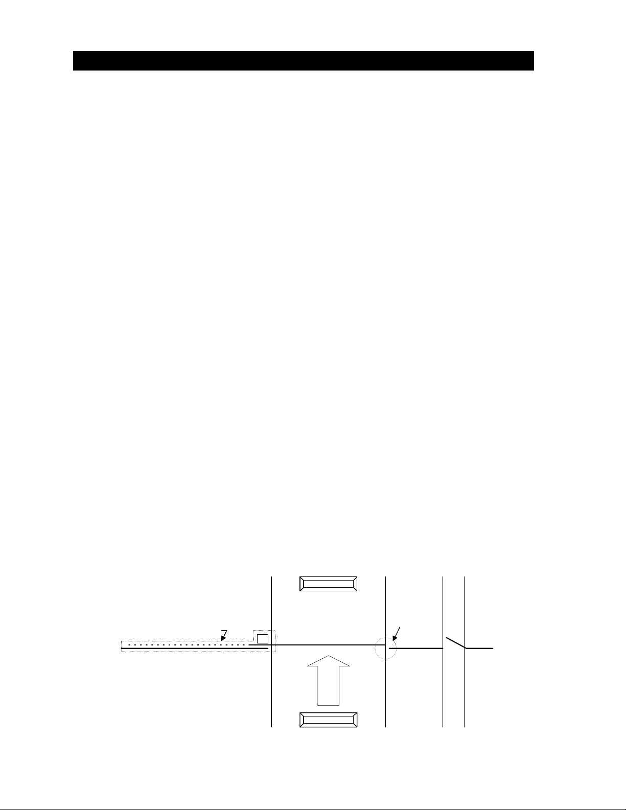
EXTERNAL ENTRAPMENT PROTECTION
Non-contact and/or contact sensors must be installed individually or in combination with each other to
provide external entrapment protection. For gate operators utilizing a non-contact sensor:
• See diagram below for placement of non-contact sensors.
• Care should be exercised to reduce the risk of nuisance tripping, such as when a vehicle trips
the sensor while the gate is still moving, and
• One or more non-contact sensors shall be located where the risk of entrapment or
obstruction exists, such as the perimeter reachable by a moving gate or barrier.
Open beam protects area
between the gate and
adjacent fence during the
Fence
open cycle.
Gate
Entrapment area exist between the gate
and the adjacent fence when the gate is in
the opening cycle.
Close beam prevents gate
from hitting obstructions
during the close cycle.
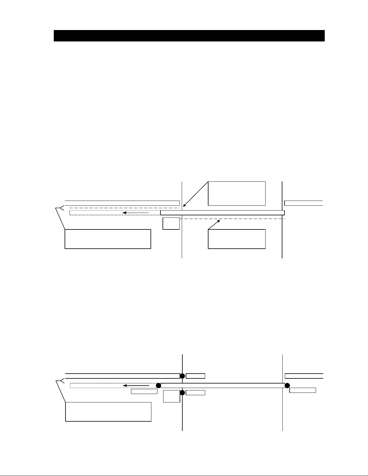
For gate operators utilizing a contact sensor:
• A hardwired contact sensor shall be located and it’s wiring arranged so that the
communication between the sensor and the gate operator is not subjected to mechanical
damage.
• A wireless contact sensor such as one that transmits radio frequency (RF) signals to the gate
operator for entrapment protection functions shall be located where the transmission of the
signals are not obstructed or impeded by building structures, natural landscaping or similar
obstruction. A wireless contact sensor shall function under the intended end-use conditions.
Fence
Trailing Edge
Entrapment area exist between the gate
and the adjacent fence when the gate is in
the opening cycle.
Outside
Inside
Gate
Leading Edge
vii

GLOSSARY
GATE – A moving barrier such as a swinging, sliding, raising, lowering, or the like, barrier, that is a
stand-alone passage barrier or is that portion of a wall or fence system that controls entrance and/or
egress by persons or vehicles and completes the perimeter of a defined area.
RESIDENTIAL VEHICULAR GATE OPERATOR-CLASS I - A vehicular gate operator (or system)
intended for use in a home of one-to four single family dwelling, or garage or parking area associated
therewith.
COMMERCIAL / GENERAL ACCESS VEHICULAR GATE OPERATOR-CLASS II - A vehicular gate
operator (or system) intended for use in a commercial location or building such as a multi-family
housing unit (five or more single family units), hotels, garages, retail store, or other building servicing
the general public.
INDUSTRIAL / LIMITED ACCESS VEHICULAR GATE OPERATOR-CLASS III - A vehicular gate
operator (or system) intended for use in an industrial location or building such as a factory or loading
dock area or other locations not intended to service the general public.
RESTRICTED ACCESS VEHICULAR GATE OPERATOR-CLASS IV - A vehicular gate operator (or
system) intended for use in a guarded industrial location or building such as an airport security area
or other restricted access locations not servicing the general public, in which unauthorized access is
prevented via supervision by security personnel.
SYSTEM - In the context of these requirements, a system refers to a group of interacting devices
intended to perform a common function.
WIRED CONTROL - A control implemented in a form of fixed physical interconnections between the
control, the associated devices, and an operator to perform predetermined functions in response to
input signals.
WIRELESS CONTROL - A control implemented in means other than fixed physical interconnections
(such as radio waves or infrared beams) between the control, the associated devices, and an
operator to perform predetermined functions in response to input signals.
INHERENT ENTRAPMENT SENSOR SYSTEM - An automatic sensor system, which senses
entrapment of a solid object and is incorporated as a permanent and integral part of the operator.
ENTRAPMENT – The condition when an object is caught or held in a position that increases the risk
of injury.
viii

TABLE OF CONTENTS
Section 1 – Installation
1.1 Specifications ...........................................................................................................................................1
1.2 Mounting Positions
1.2.1 Front Position Pad Mount.........................................................................................................2
1.2.2 Front Position Post Mount........................................................................................................2
1.2.3 Rear Position Pad or Post Mount.............................................................................................3
1.2.4 Center Position Post Mount .....................................................................................................3
1.3 Mounting Options
1.3.1 Pad Mounted Operators...........................................................................................................4
1.3.2 Post Mounted Operators ..........................................................................................................5
1.4 Operator Installation
1.4.1 Pad Mounted Operators...........................................................................................................6
1.4.2 Post Mounted Operators ..........................................................................................................6
1.5 Chain Installation
1.5.1 Front – Pad Mount ...................................................................................................................7
1.5.2 Front – Post Mount...................................................................................................................8
1.5.3 Rear – Pad or Post Mount........................................................................................................9
1.5.4 Center – Post Mount ................................................................................................................10
1.6 Warning Sign Installation..........................................................................................................................11
Section 2 – Wiring
Conduits ...................................................................................................................................................13
2.1 High Voltage Connections........................................................................................................................14
2.2 Control Wiring...........................................................................................................................................15
2.3 Secondary Entrapment Protection Device Wiring
2.3.1 Non-Contact Sensors ...............................................................................................................16
2.3.2 Contact Sensors.......................................................................................................................17
2.4 Loop Detector Wiring................................................................................................................................18
2.5 Gate Tracker™ Connections....................................................................................................................19
2.6 Auxiliary Devices
2.6.1 Alarm Reset Switch..................................................................................................................20
2.6.2 Auxiliary Stop Switch................................................................................................................20
2.7 Master / Slave Wiring
2.7.1 Operator Interface ....................................................................................................................21
2.7.2 Secondary Entrapment Protection Device Wiring ....................................................................22
2.8 Terminal Identification and Description
2.8.1 Main Terminals.........................................................................................................................23
2.8.2 Auxiliary Terminals...................................................................................................................24
Section 3 – Adjustments
3.1 Circuit Board Adjustments........................................................................................................................25
3.2 Switch Settings.........................................................................................................................................26
3.2.1 SW 1 (Left Switch) Description and Function...........................................................................27
3.2.2 SW 2 (Right Switch) Description and Function ........................................................................27
3.3 Limit Adjustment.......................................................................................................................................28
3.4 Inherent Reverse Adjustment
3.4.1 Reverse Sensitivity Adjustment................................................................................................29
3.4.2 Clutch Adjustment ....................................................................................................................30
ix

Section 4 – Operating Instructions
4.1 Power and Reset Switches.......................................................................................................................31
4.2 Shutdown Conditions
4.2.1 Soft Shutdown ..........................................................................................................................32
4.2.2 Resetting a Soft Shutdown.......................................................................................................32
4.2.3 Hard Shutdown.........................................................................................................................33
4.2.4 Resetting a Hard Shutdown .....................................................................................................33
4.3 Manual / Emergency Gate Operation
4.3.1 Emergency Vehicle Access Conditions....................................................................................34
4.3.2 Fail-Safe Manual Operation .....................................................................................................34
4.3.3 Fail-Secure Manual Operation .................................................................................................35
Section 5 – Maintenance and Troubleshooting
5.1 Maintenance Schedule .............................................................................................................................37
5.2 Trouble Shooting ......................................................................................................................................38
5.3 Accessories ..............................................................................................................................................41
Wire Diagram............................................................................................................................................42
Illustrated Parts Breakdown......................................................................................................................43
x
SECTION 1 - INSTALLATION
Prior to beginning the installation of the slide gate operator, we suggest that you become familiar with
the instructions, illustrations, and wiring guide-lines in this manual. This will help insure that your
installation is performed in an efficient and professional manner.
The proper installation of the vehicular slide gate operator is an extremely important and integral part
of the overall access control system. Check all local building ordinances and building codes prior to
installing this operator. Be sure your installation is in compliance with local codes.
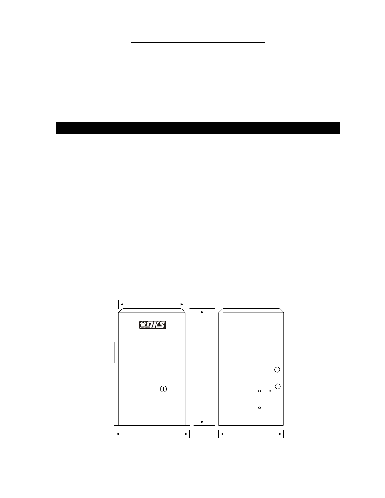
1.1 SPECIFICATIONS
Class of Operation: Class I, II, III, IV
Type of Gate: Vehicular Slide Gates Only
Horsepower: 1/2 H.P.
Voltage / Phase: 115 VAC Single-phase only
Current: 5.4 amps
Max Gate Weight: 1000 Lbs.
Max Gate Length: 30 Ft.1
Cycles / Hr: 60/Hr
Speed: Approximately 1 Ft./Sec.
Entrapment Protection: Primary – Inherent (Type A)
Secondary – Provision for connection of a non-contact
sensor (Type B1) and/or a contact sensor (Type B2).
Secondary entrapment protection devices are not supplied
with the operator and must be ordered separately.
Note 1: Assumes gate is in good working condition installed on a
level surface.
1
12
24
14.75 11.5
Figure 1
1
1.2 MOUNTING POSITIONS
The Model 9100 operator is designed so that it can be installed in any of the mounting positions
shown below. Once the mounting position has been determined, the chain idlers must be adjusted to
accommodate the mounting position chosen before the operator is mounted to the pad or post. The
idlers are factory set for the front, pad mount position. (Note: Rear and center position, and postmounted operators require additional hardware not supplied with the operator).
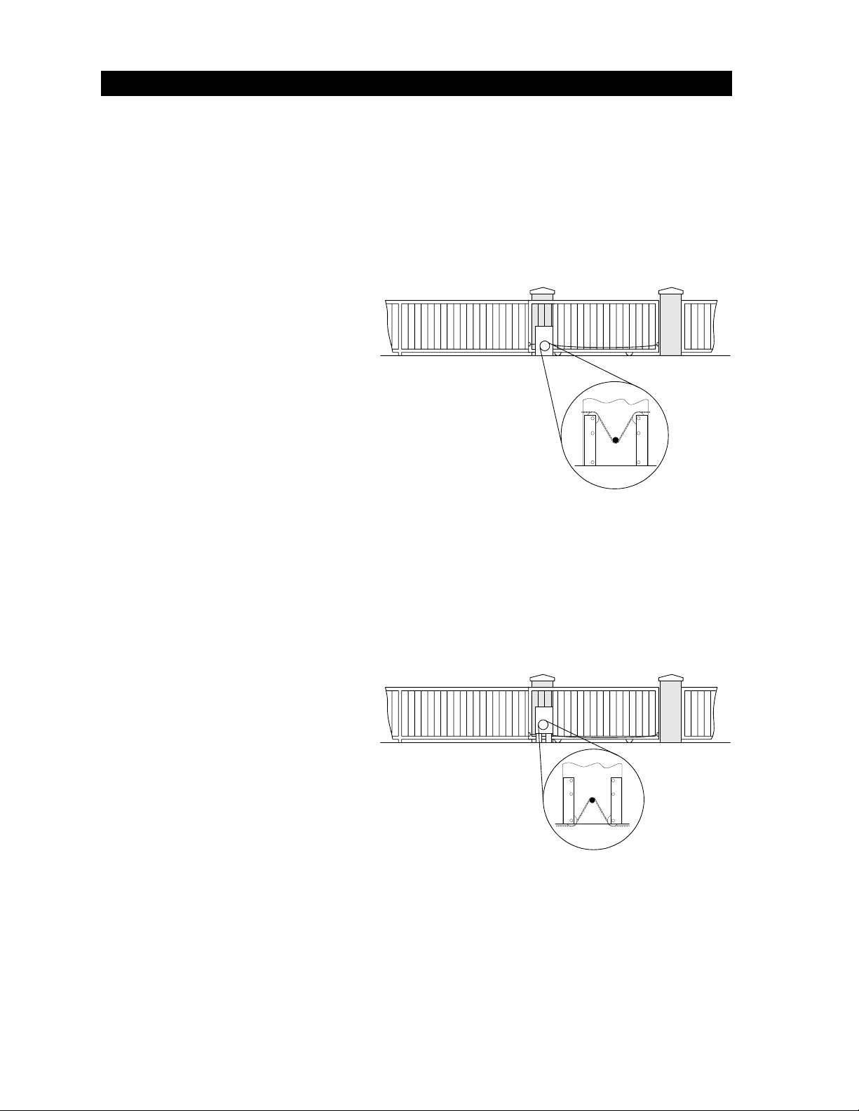
1.2.1 FRONT POSITION PAD MOUNT
• This is considered the standard
method of installing slide gate
operators.
• Set both chain idlers in the top
position (factory setting).
• Remove the TOP chain knockouts
from each side of the operator.
• Chain passes through the
operator and is attached to each
end of the gate.
1.2.2 FRONT POSITION POST MOUNT
• Set both chain idlers in the
bottom position.
• DO NOT remove chain
knockouts. Using this mounting
method, the chain enters and
exits the operator from the
bottom.
• Chain passes through the
operator and is attached to each
end of the gate.
• This mounting method allows for
the use of chain support
attached to the gate. This is useful with long gates and helps prevent chain “stretching.”
Figure 2
Figure 3
• ADDITIONAL HARDWARE REQUIRED: Post Mount Base Plate P/N 2600-418 and two (2)
4” x 4” steel mounting post at least three feet in length. Mounting post are not available from
DoorKing.
2
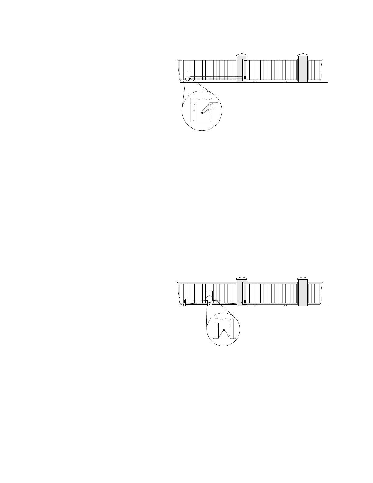
1.2.3 REAR POSITION PAD OR POST MOUNT
• Set one chain idler at the top
position and one chain idler at
the center position on the same
side of the operator.
• Remove the top and bottom
chain knockouts from the side of
the operator.
• Chain enters and exits the
operator from the same side.
Chain is attached to one end of
the gate.
• This mounting method hides the
Figure 4
chain when looking at the gate
from the front.
• ADDITIONAL HARDWARE REQUIRED: Endless Idler Assembly P/N 2600-818. Additional
length of #41 Chain P/N 2600-441 (20 ft.). Note: additional chain may be required depending
on the length of the gate.
• If operator is post mounted: Post Mount Base Plate P/N 2600-418 and two (2) 4” x 4” steel
mounting post at least three feet in length. Mounting post are not available from DoorKing.
1.2.4 CENTER POSITION POST MOUNT
• Set both chain idlers in the bottom
position.
• DO NOT remove chain knockouts.
Using this mounting method, the
chain enters and exits the
operator from the bottom.
• Chain passes through the
operator and is attached to one
end of the gate.
• This mounting method allows for
Figure 5
the use of chain support
attached to the gate. This is useful with long gates and helps prevent chain “stretching.”
• ADDITIONAL HARDWARE REQUIRED: Two (2) Endless Idler Assemblies P/N 2600-818.
Additional length of #41 Chain P/N 2600-441 (20 ft.). Note: additional chain may be required
depending on the length of the gate. Post Mount Base Plate P/N 2600-418 and two (2) 4” x
4” steel mounting post at least three feet in length. Mounting post are not available from
DoorKing.
3
1.3 MOUNTING OPTIONS
Pad mounting can be used when the operator will be installed using either the front or rear mounting
position. If the operator is to be center mounted, the post mounting method must be used.
1.3.1 PAD MOUNTED OPERATORS
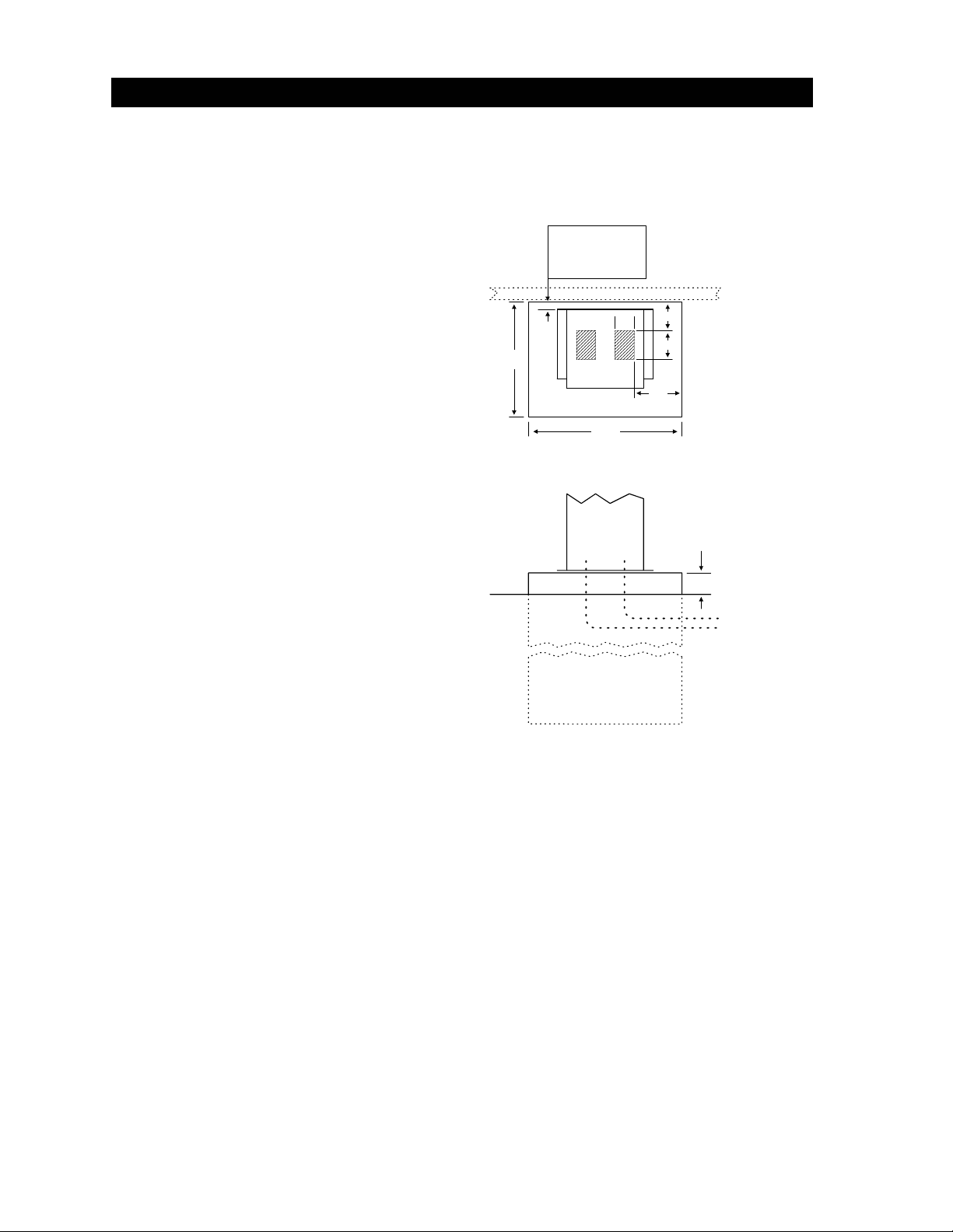
1. Construct a form for the mounting pad
according to the specifications shown in
figure 6. Be sure to level the top edge of
the form and that the top of the form is a
minimum of four (4) inches above ground
level. We suggest that you contact the
local building department to determine
the required depth of the pad since soil
conditions and code requirements vary
from city to city.
2. Set conduits, reinforcing bars and/or wire
mesh if required. The number of conduits
is determined by the application
requirements. We suggest using a
minimum of four (4) conduits. 1-High
voltage power lines; 2-Low voltage
control lines; 3-Loop lead-in wires (open
loop); 4-Loop lead-in wires (reverse
loops). See SECTION 2. Set additional
conduits as required for your application.
NOTE: If conduits are not set in the pad,
they can be routed to a J box where
connections to the operator can be made
after it is installed. There are three (3) ½inch knockouts and one (1) ¾-inch
knockout on each side of the operator for
this purpose.
3. Mix the concrete according to the
manufacturers instructions. Pour the
mixture into the form and tamp. Level
and finish the surface after pouring is
complete. Do not set anchor bolts in the
concrete. Sleeve anchors should be
used to secure the operator to the pad.
This allows greater flexibility in
positioning the operator on the pad.
4. Allow the pad to cure for 48 hours before
removing the forms or mounting the
operator.
18
Minimum 1"
clearance between
gate and back of
operator.
3.5
24
Figure 6
2.5
6.5
Conduits can
be located in
shaded areas.
7
4" minimum above
ground level
Ground Level
Depth of pad
determined by
soil conditions
and local code
Gate
Conduits
4
1.3.2 POST MOUNTED OPERATORS
Post mounting can be used when the operator will be installed in any of the three mounting positions,
and must be used if the operator is to be center mounted.
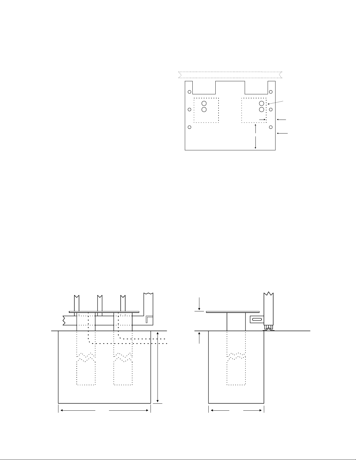
1. Post mounting the operator requires
the use of an operator base plate
(P/N 2600-418) and two (2) 4 X 4
steel post (not supplied) welded to
the base plate as shown in figure 7.
The length of the steel post and the
depth of the pad are determined by
soil conditions and local code
requirements. We suggest that you
contact the local building department
to determine the required depth of
4.5
the pad since soil conditions and
code requirements vary from city to
city.
Figure 7
2. After the posts have been welded to
the base plate to form the mounting plate assembly, construct a form for the assembly
according to the specifications in figure 8.
3. Position the mounting plate assembly into the form. Be sure that the base plate is a
minimum of four (4) inches above ground level. Set conduits, reinforcing bars and/or wire
mesh if required. The number of conduits is determined by the application requirements.
We suggest using a minimum of four (4) conduits. 1-High voltage power lines; 2-Low
voltage control lines; 3-Loop lead-in wires (open loop); 4-Loop lead-in wires (reverse
loops). See SECTION 2. Set additional conduits as required for your application.
NOTE: If conduits are not set in the pad, they can be routed to a J box where
connections to the operator can be made after it is installed. There are three (3) ½-inch
knockouts and one (1) ¾-inch knockout on each side of the operator for this purpose.
IMPORTANT!! Be sure that the mounting plate is level and parallel with the gate.
4. Secure the mounting plate assembly in the form. Mix the concrete according to the
manufacturers instructions. Pour the mixture into the form and tamp. Level and finish the
surface after pouring is complete.
5. Allow the pad to cure for 48 hours before removing the forms or mounting the operator.
Gate
4 x 4 Steel Post
(not supplied)
1.5
Base Plate
P/N 2600-418
4 inch
minimum
Conduits
Depth of pad
determined by
soil conditions
and local code.
Figure 8
5
1220
1.4 OPERATOR INSTALLATION
Prior to mounting the gate operator, be sure that the chain knockouts and chain idlers are set for the
mounting position (front, center or rear) and the mounting option chosen (pad or post). Refer back to
SECTION 1.2.
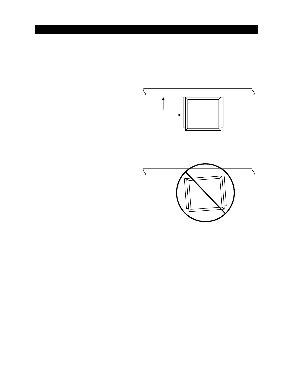
1.4.1 PAD MOUNTED OPERATORS
• Position the operator on the pad
so that there is a minimum
clearance of one (1) inch between
the back of the operator housing
and the gate.
• IMPORTANT!! Be sure that the
operator is parallel to the gate!
Installing the operator in any other
manner will cause excessive
chain noise, chain wear and
stretching, and premature idler
failure.
• Mark the mounting holes on the
mounting pad. Use a concrete
drill bit to drill the mounting holes
to the size and depth required for
the anchors being used. We
recommend minimum 3/8 x 2
sleeve anchors (not supplied).
• After drilling the mounting holes,
clean them out and install the
sleeve anchors. Position the
operator over the anchors and
tighten.
1.4.2 POST MOUNTED OPERATORS
90°
Figure 9
• Position the operator on the mounting plate so that the mounting holes are in alignment. If
the mounting plate/post assembly has been installed correctly, there should be a minimum of
one (1) inch clearance between the back of the operator housing and the gate, and the
operator should be parallel to the gate. If these conditions do not exist, make corrections
now!
• IMPORTANT!! Be sure that the operator is parallel to the gate! Installing the operator in any
other manner will cause excessive chain noise, chain wear and stretching, and premature
idler failure.
• Secure the operator to the mounting plate/post assembly using six (6) ½-13 x 1 ½ bolts, lock
washers and nuts (or equivalent hardware). NOTE: Hardware is not supplied with the
operator or mounting plate.
6
 Loading...