

DK-LOK Tube Fittings User Manual

DK-Lok Tube Fittings
No.01-6
June 2015
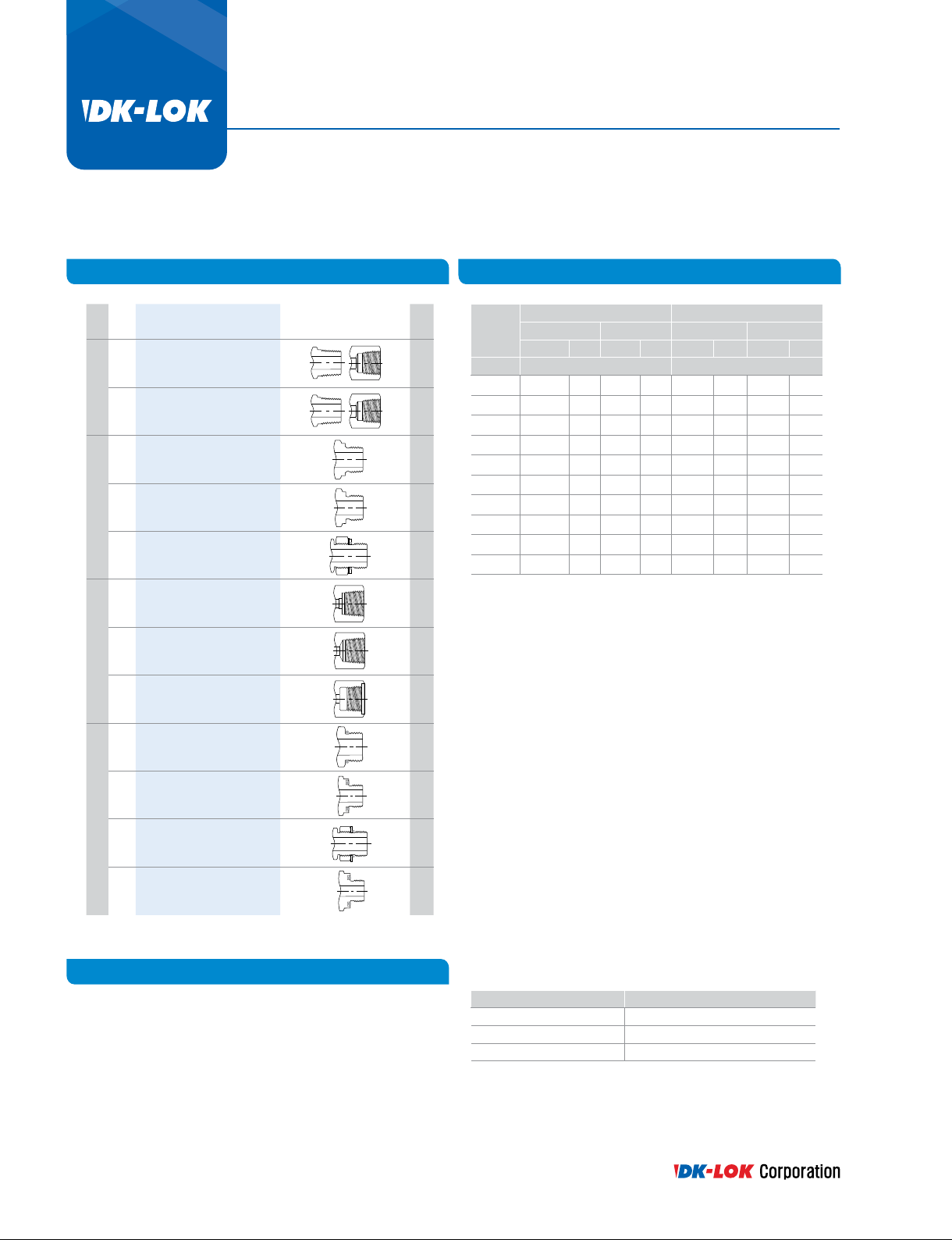
Tube Fittings
Technical Information
Tube to Tube Union
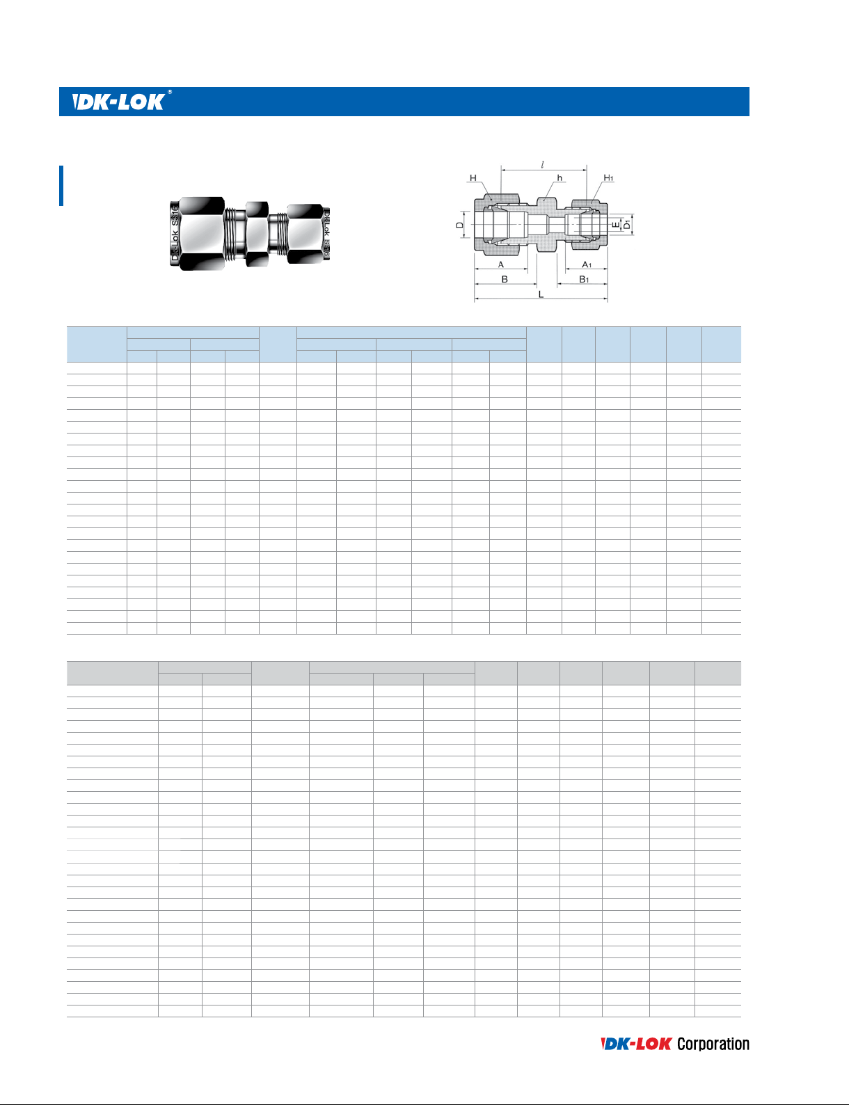
Union
DU
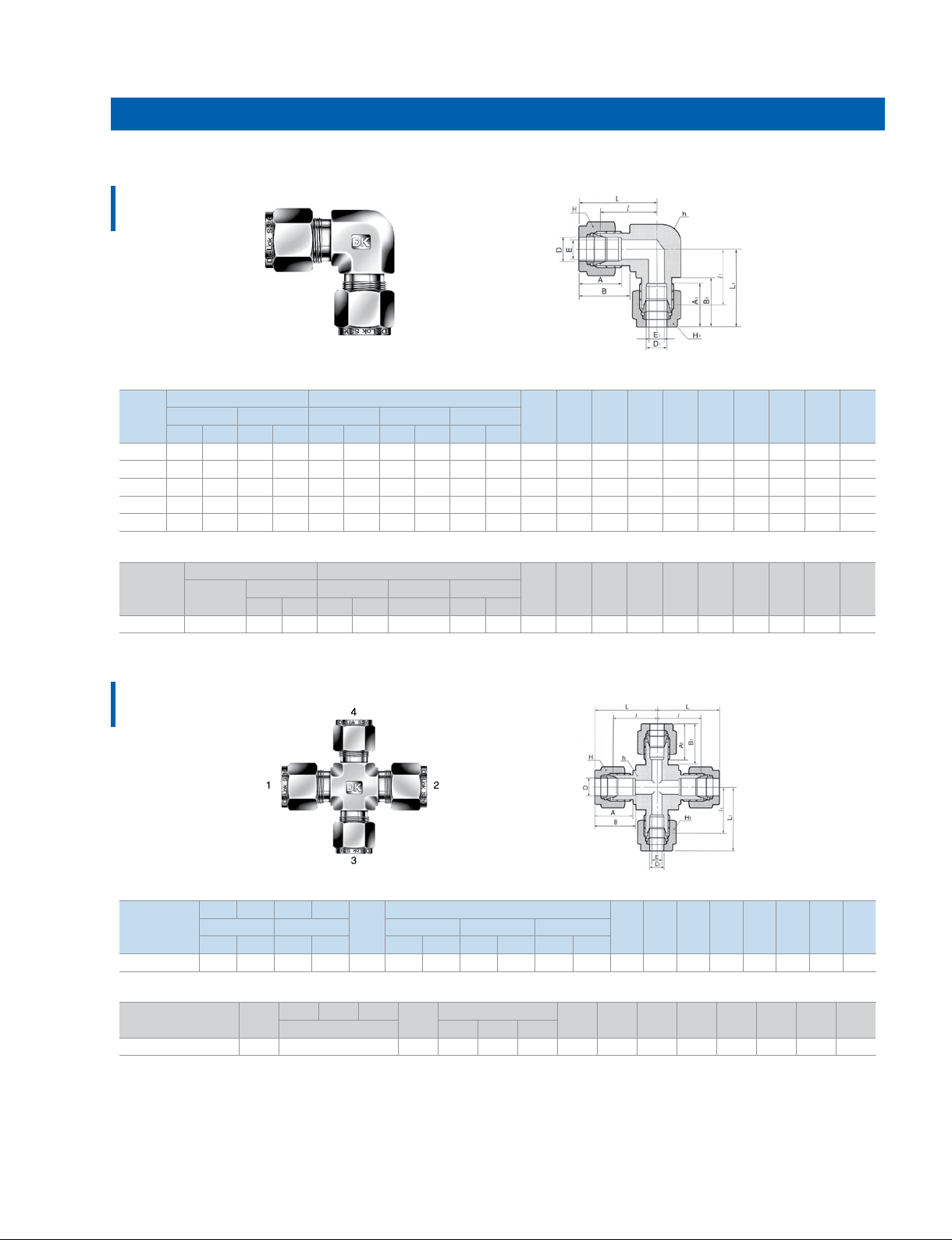
Union Elbow
DL
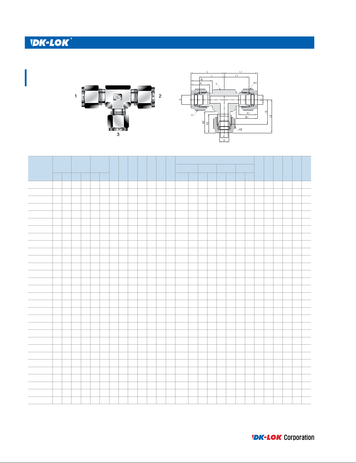
Union Tee
DT
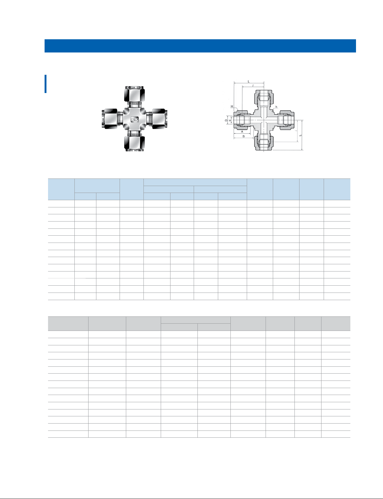
Union Cross
DX
Bulkhead Union
DUB
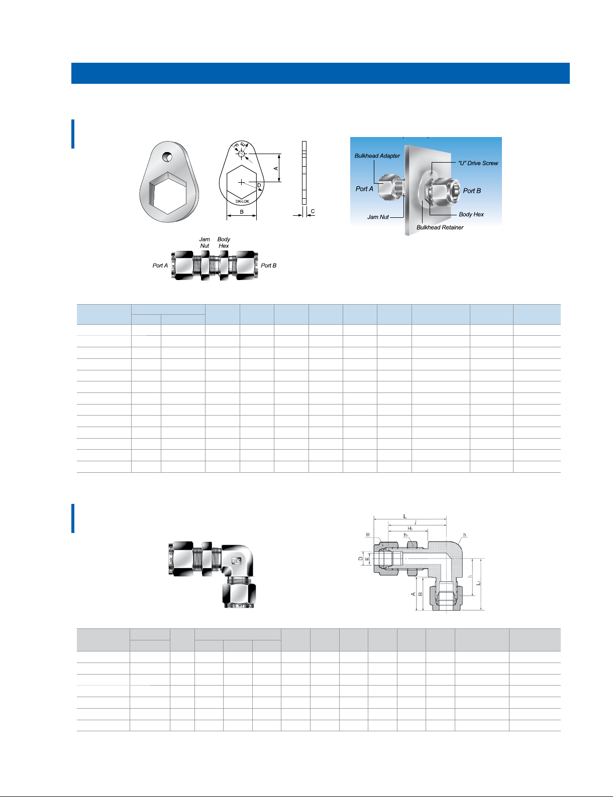
Bulkhead Retainer
DBR
Bulkhead Elbow
Union
DBL
Reducing Union
DUR
Reducing Union
Elbow
DLR
Reducing Union
Cross
DXR
Reducing Union
Tee
DTR
Tube to Male Pipe
Male Connector
DMC-N
Male Connector
DMC-R
Thermocouple
Connector
DMCT
Male Connector for
Bonded Gasket Seal
DMC-G
11
Male Connector
for Metal Gasket
12
DMC-GB, -G
Bulkhead Male
Connector
13
DMCB-N
45° Male Elbow
14
DLBM
Male Elbow
15
DLM-N
Male Elbow
16
DLM-R
Male Run Tee
DTRM-N
16
Male Run Tee
DTRM-R
17
Male Branch Tee
DTBM-N, -R
Male Branch Tee
18
DTBM-N
Male Branch Tee
18
DTBM-R
19
Tube to Female Pipe
20
Female Connector
DCF-N
Female Connector
21
DCF-R
22
Gauge Connector
23
DCF-GG
24
Bulkhead
Female Connector
DCBF-N
23
Female Elbow
DLF-N
Female Run Tee
25
DTRF-N
Female Branch Tee
25
DTBF-N
26
Tube Stub Connector
28
Reducer
29
DR
29
Bulkhead Adapter
DAB
30
Male Adapter
31
DAM-N
32
Male Adapter
33
DAM-R
34
Male Adapter
DAM-G
35
Male Adapter
DAM-U
36
Male Adapter
DAM-UO
37
Female Adapter
DAF-N
38
Female Adapter
DAF-R
Female Adapter
DAF-GR
39
Female Gauge
40
Adapter
DAF-GG
41
Elbow Adapter
DLA
42
Run Tee Adapter
DTRA
43
Branch Tee Adapter
DTBA
44
45
46
47
48
49
49
50
51
52
53
53
54
55
55
56
57
57
57
1
All dimensions are in millimeters unless otherwise specied and only for reference subject to change.
Port Connector
DCP/DCPZ
Reducing Port
Connector
DCRP
DK-Lok Flanges
DK-Lok Flanges
DF
Lab Joint
Flange Connector
DLJ
Tube to AN Tube
AN Union
DUA
AN Bulkhead Union
DUBA
Male AN adapter
DMAA
AN Adapter
DAA
Tube to Non-Positionable O-Seal
O-Seal Straight
Thread Connector
DMC-UO
O-Seal Pipe
Thread Connector
DMC-NO
Non-Positionable
SAE Male Connector
DMCS-U
Tube to Positionable
Straight Thread
Posiotanable SAE
Male Elbow
DLS-UP
Positionable
45° SAE Male Elbow
58
DLBS-UP
Positionable
59
SAE Male Run Tee
DTRS-UP
Positionable
SAE Male Branch Tee
DTBS-UP
59
60
Positionable Male Elbow
ISO Parallel thread
DLM-GP
60
Tube To Weld End
Male Pipe
Weld Connector
DCW
61
Male Pipe
Weld Elbow
61
DLW
Tube Socket
Weld Connector
62
DCSW
Tube Socket
62
Weld Elbow
DLSW
Welding Bulkhead
Union
DBUW
63
Plug, Cap, Insert
Plug
63
DP
Cap
64
DC
Tube Insert
DI
65
AdditionalProducts
66
Fuse Plug
DFA
Vent Protector
66
DMD
Calibration Fittings
66
DPCM
Dielectric Fittings
67
DEU
Spare Parts
Gasket
DGV/DGB
68
DGC/DGG
Nut
69
DN
Ferrule Set
DFS
69
Nut-Ferrule Set
DFSN
Front Ferrule
70
DFF
Back Ferrule
70
DFB
Tools
Preswaging Tool
70
DPS
Gap Gauge
71
DIG
Tube Depth
Marking Tool
72
DTM
Pre-Swaging Unit
DHS-2A
Pre-Swaging Unit
DES-1A
72
73
73
74
27
75
75
75
76
76
76
77
77
77
77
All dimensions are in millimeters unless otherwise specied and only for reference subject to change.
www.dklok.com
2
Tube Fittings
Technical Information
The Premium Quality DK-Lok Tube Fittings
DK-Lok Tube Fitting is designed using industrial codes and
specications with additional Cutting-Edge Engineering on
swaging action and sealing integrity. DK-Lok provides excellent
leak-free sealing on high pressure gas, vacuum, impulse, thermal
shock, heavy vibration, and many other stringent applications.
DK-Lok brings you truly excellent quality, outstanding customer
service, and availability.
Enjoy DK-Lok tube tting working on your application!
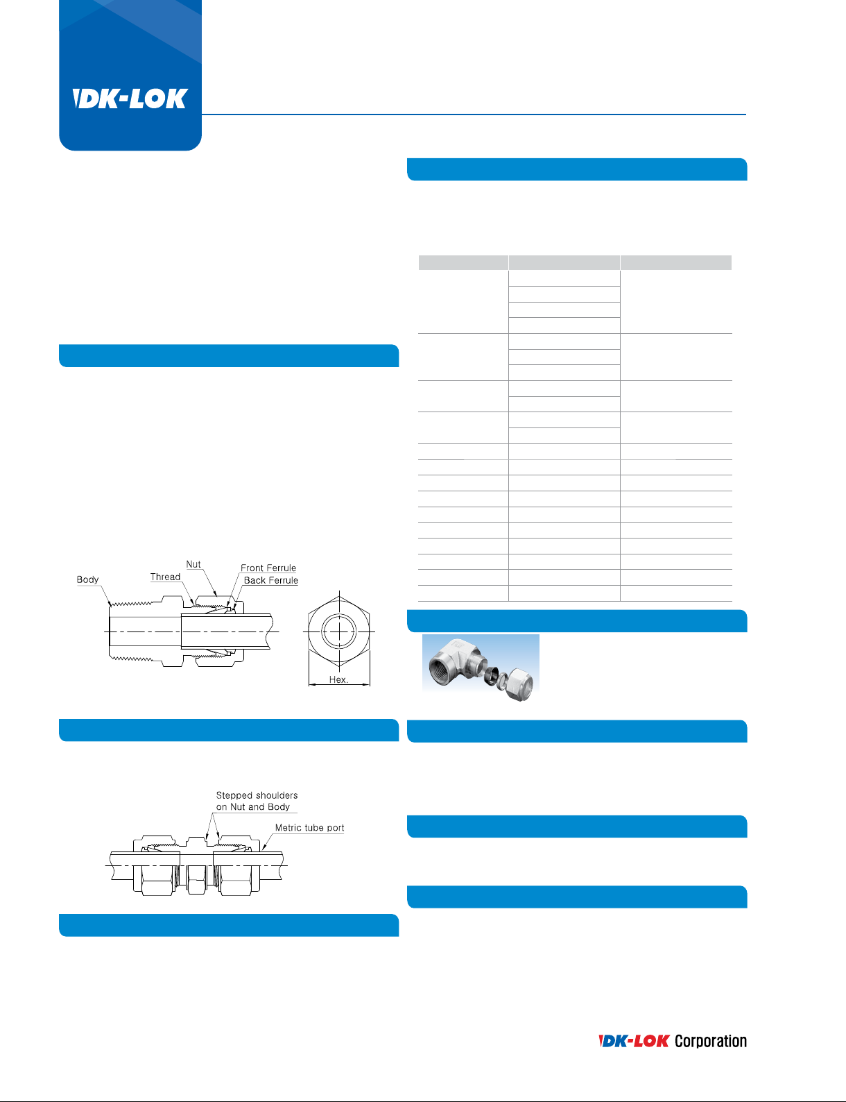
Construction of DK-Lok Tube Fittings
DK-Lok Tube Fitting consists of body, front ferrule, back ferrule and
nut. The features include;
tExcellent product range up to 2 in. and 50 mm OD.
t Additional engineering on sealing integrity and swaging action.
tRe-usable and predictable quality.
tGaugable.
t Excellent leak-free sealing integrity on heavy vibration, vacuum
and impulse.
tHeat-Code Traceability.
t No torque transferring to connective tubing during installation.
DK-Lok Material Standards
DK-Lok tube tting are supplied in various materials to satisfy the
needs of various applications including on shore oil& gas, renery,
oshore oil& gas, chemical, petrochemical, analytical instrumentation,
steel mill, power plant, shipbuilding, pharmaceutical, and alternative
fuel.
Material Bar stock Forging
ASTM A276
Stainless Steel316
Brass
Carbon Steel
Duplex
Super Duplex ASTM A479 S32750 ASTM A182 F51
Aluminum ASTM B211 Alloy 2024 T6 ASTM B247
Alloy 20 ASTM B473 UNS N08020 ASTM B462 UNS N08020
Hastelloy C276 ASTM B574 UNS N10276 ASTM B564 UNS N10276
Alloy 400 ASTM B164 UNS N04400 ASTM B564 UNS N04400
Alloy 600 ASTM B166 UNS N06600 ASTM B564 UNS N06600
Alloy 625 ASTM B446 UNS N06625 ASTM B564 UNS N06625
Alloy 825 ASTM B425 UNS N08825 ASTM B564 UNS N08825
Titanium Gr. 2 ASTM B348 Gr.2 ASTM B381 F3
PTFE ASTM D1710 ASTM D3293
ASTM A479
ASME SA479
JIS G4303
ASTM B16 UNS C36000
JIS H3250 Alloy C3604
ASTM A675 Gr.60-90
JIS G4051 S20C - S48C
ASTM A276 S31803
ASTM A479 S31803
ASTM A182
ASME SA182
JIS G3214
ASTM B283 UNS C37700
JIS H3250 Alloy C3771ASTM B453 UNS C35300
ASTM A105
JIS G4051 S20C - S48C
ASTM A182 F51
Identication of Metric DK-Lok Tube Fitting
Metric DK-Lok tube tting has stepped shoulder on body and nut
hex. Shaped tting such as tee, elbow, and cross forging has such
step on body as well.
Product Cleaning
Every DK-Lok tube tting is cleaned to remove surface contamination,
iron particles from cutting tools, oil from cutting uid, and loose particles.
For further information refer to DK cleaning standard DC-01.
Specialcleaning for oxygen service application is available on request.
Refer to specialcleaning standard DC-11.
Carbon Steel DK-Lok Tube Fittings
Carbon steel ttings are white zinc plated.
Every carbon steel tting is supplied with
SS316 back ferrule and Carbon Steel front
ferrule with black fast plated.
O-ring
DK-Lok tting pipe end with O-ring is supplied; 70 durometer NBR
O-ring on Brass and Carbon steel ttings, 90 durometer FKM O-ring
on Stainless steel tting.
Other O-ring is available on request.
DK-Lok Port Dimension
Dimensions on DK-Lok Port in the catalog are approximate gures
and shown in nger-tight position.
Alternative Fuels
Stainless steel316 DK-Lok Tube Fittings are tested to the requirements
of ECE R110, EIHP Draft, ECE R67 and certied by TUV.
3
All dimensions are in millimeters unless otherwise specied and only for reference subject to change.
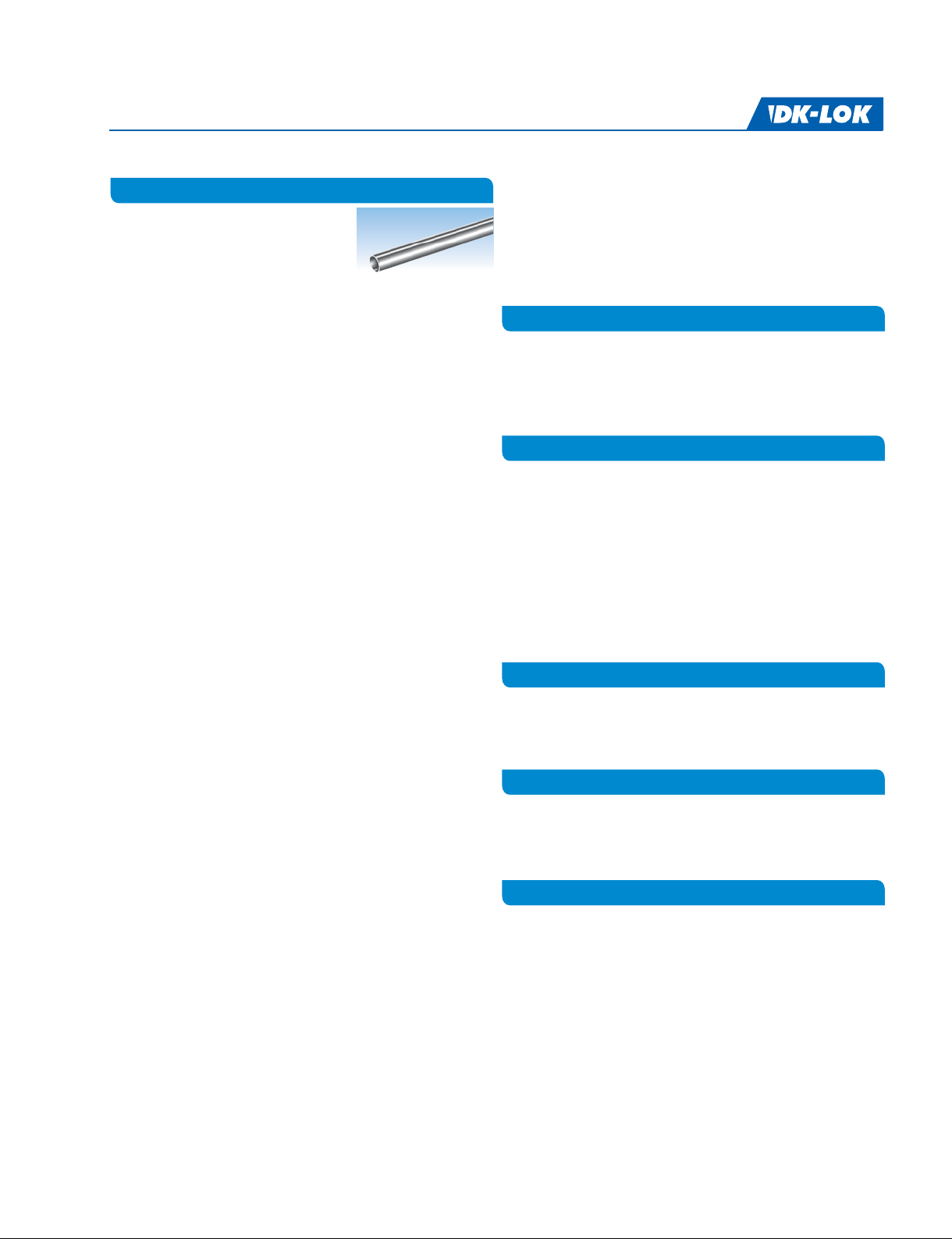
Tubing
For safe, reliable and leak-free DK-Lok tting
system, tubing should be considered as one
of tting components.
t Tubing is assembled by simple wrench
make-up on DK-Lok fitting. This results in
less assembly and maintenance costs.
tTubing assembly on DK-Lok fitting is re-usable.
t Tubing is bendable. It allows lower pressure drop with fewer
connections. This in turn reduces system costs because of less
fabricating manpower.
t Pipe threading or welding is difficult to disassemble and
re-assemble
t Piping requires skilled worker for welding & threading
DK-Lok Tube Fitting Pressure Rating
t The pressure rating of DK-Lok Tube Fitting is rated to the working
pressure of connective tubing.
t The allowable working pressure of tubing in various materials is
listed in the table 2 to 13.
Material
Using like tubing and tting materialis essential for leak-free sealing
Material
system.
Unlike material may have dierent mechanical properties that may adversely aect the tting seal on tubing.
The only exception is copper tubing with brass DK-Lok tting.
Tubing Selection
Hardness
t Tubing must be softer than fitting material. The metal tubing
must be fully annealed and suitable for bending and flaring.
t Tubing hardness must be selected according to the information
in the table 2 to 13.
Surface
t Tubing must have a surface free from scratches, draw mark, dirt,
dust and flat spots.
Ovality
t Tubing in oval or out-of-roundness way not fit into the fitting.
Do not force the tubing into the fitting; it may damage the fitting
sealing system on nut, ferrules, and body.
Wallthickness
t The table 2 to 13 list tubing working pressure ratings in a wide
range of wall thickness. A too thin wall may collapse and a too
thick wall may not properly be deformed by the ferrule action.
t Do not use tubing wall thickness not listed in the table 2 to 13.
Weld tubing
t Welded tubing should have a not measurable bead on its outside
diameter.
Tubing Handling
Careful handling and storage practices will protect tubing from
unnecessary scratches, nicks, or degrading the good tubing surface
nish.
t Tubing ends should be capped so any foreign materials will not
fall inside during transportation and storage.
t Do not drag across tubing rack, cement, gravel or any rough
surface.
t Do use correct tube cutter for tube material. The wrong cutter
may result in excessive deformation of the tube end.
t Do not cut deep with each turn of cutting.
tTube cutters and hacksaws should be sharp enough.
tHacksaw blades should have at least 32 teeth per inch.
tDo deburr tube ends before inserting in fittings.
Gas Application
DK-Lok tube tting is designed for a wide range of leak-free application
including gas leak proof and vacuum tight service.
Gases (helium, hydrogen, nitrogen, air, etc.) can escape even the most
minute leak-path due to their very small molecules.
Tube therefore must be handled not to have scratches, draw mark,
nicks, at spots, dirt, and dust
Use NOT thin wall tubing for gas applications.
Heavier wall tubing resists the ferrule action whereas thin walltubing
may collapse with little resistance to ferrule action.
For Gas service, use the tubing wall listed on un-shadowed section in
table 2 to 13.
Vacuum Application
DK-Lok Tube Fittings have been proved to be excellent vacuum tight
seal in many applications including analytical industry.
DK-Lok Tube Fittings comply with the leakage requirements of TA-LUFT
2002.
Cryogenic Application
DK-Lok Fittings in SS316 Stainless Steel provide highly reliable
performance on cryogenic application.
Cryogenic temperature is considered to be temperatures below
-100℉ (-73℃).
High Pressure Application
Pressure 500 psig (34.5 bar) or higher is considered generally high
pressure. In the high pressure system scratches, draw mark, nicks,
at spots, and dirt on tubing may cause leakage
t For gas application, select the gas applicable tubing wall
thickness from Table 2 to 13.
t Follow the suggestion on tubing selection, handling, and
installation.
All dimensions are in millimeters unless otherwise specied and only for reference subject to change.
www.dklok.com
4
Technical Information
Tube Fittings
Stainless Steel Tubing
Table 2. Fractional Seamless Stainless Steel Tubing
Fully annealed austenitic Type 304 or 316 seamless tubing ASTM A269 or ASTM A213, or equivalent. Tubing to be free from scratches, draw mark,
dirt, dust, at spots, and suitable for bending and aring. Recommended hardness : 80 HRB or less.
OD
in.
0.012 0.014 0.016 0.02 0.028 0.035 0.049 0.065 0.083 0.095 0.109 0.12 0.134 0.156 0.188
1/16 6800 8100 9400 12000
1/8 8500 10900
3/16 5400 7000 10200
1/4 4000 5100 7500 10200 Working Pressure in psig
5/16 4000 5800 8000
3/8 3300 4800 6500 8600
1/2 2400 3500 4700 6200
5/8 2900 4000 5200 6000
3/4 2400 3300 4200 4900 5800 6400
7/8 2000 2800 3600 4200 4800 5400 6100
1 2400 3100 3600 4200 4700 5300
1 1/4 2400 2800 3300 3600 4100 4900
1 1/2 2300 2700 3000 3400 4000 4900
2 2000 2200 2500 2900 3600
Wall Thickness (in.)
Table 3. Metric Seamless Stainless Steel Tubing
OD
mm
3 710
6 330 420 520 670
8 310 380 490
10 240 300 380
12 200 240 310 380 430 Working Pressure in bar
14 180 220 280 340 390 430
15 170 200 260 320 360 400
16 190 240 300 330 370
18 170 210 260 290 320 370
20 150 190 230 260 290 330 380
22 130 170 210 230 260 300 340
25 180 200 230 260 300 320
28 180 200 230 260 280 330
30 170 190 210 240 260 310
32 160 170 200 230 240 290 330
38 140 170 190 200 240 280 310
50 150 180 210 240
•
According to the requirements of ASME B31.3 Process Piping Code and ASME B31.1 Power Piping Code, allowable working pressure
0.8 1.0 1.2 1.5 1.8 2.0 2.2 2.5 2.8 3.0 3.5 4.0 4.5
Wall Thickness (mm)
calculated at -20 to 100℉ (-28 to 37℃) using S value of 20,000 psi.
t Pressure calculations are based on maximum O.D. and minimum wallthickness and no allowance is made for corrosion and erosion.
i.e., ASTM A269 1/2 in. OD x 0.035 in.WT: OD tolerance ± 0.005 in., WT tolerance ± 15%.
Calculations are based on 0.505 in.OD x 0.0298 in. WT.
t Safety Factor is 3.75 to 1, considering ultimate tensile strength of 75,000 psi.
Weld Stainless Steel Tubing Allowable Working Pressure
To determine the working pressure of weld tubing to the requirements of ASME B31.3 Code, de-rating factors below must be applied. For single
weld tubing multiply by 0.80, and for double weld tubing multiply by 0.85:
Example: SS316 seamless 1/2 in. O.D. x 0.065 in. WT allowable working pressure: 4700 psi.
5
To determine the work pressure of the single weld tubing, multiply 4700 psi by 0.80.
4700 psig x 0.80 = 3760 psig at -20 to 100℉ (-28 to 37℃).
All dimensions are in millimeters unless otherwise specied and only for reference subject to change.
Copper Tubing
Table 4. Fractional Seamless Copper Tubing
Soft annealed seamless copper tubing ASME B75 or equivalent. Soft annealed (Temper 0) copper water tube, type K or Type LASTM B88.
Recommended hardness: 60 HRB or less.
OD
in.
1/8 2700 3600
3/16 1800 2300 3400 Working Pressure in psig
1/4 1300 1600 2500 3500
5/16 1300 1900 2700
3/8 1000 1600 2200
1/2 800 1100 1600 2100
5/8 900 1200 1600 1900
3/4 700 1000 1300 1500 1800
7/8 600 800 1100 1300 1500
1 500 700 900 1100 1300 1500
Table 5. Metric Seamless Copper Tubing
OD
mm
3 225 260
4 165 191 244 295 Working Pressure in bar
6 122 157 192 245 263
8 89 114 140 179 193
10 70 89 109 140 150 172 193
12 58 73 89 114 123 140 158
14 62 76 96 103 118 133 148 171 209
16 54 66 83 89 102 114 127 147 180
18 48 58 74 79 90 101 112 129 159
22 39 47 59 64 72 81 90 103 126
25 34 41 52 56 63 71 78 90 110
0.010 0.012 0.028 0.035 0.049 0.065 0.083 0.095 0.109 0.120
0.7 0.8 1.0 1.2 1.5 1.6 1.8 2.0 2.2 2.5 3.0
t According to the requirements of ASME B31.3 Process Piping Code and ASME B31.1 Power Piping Code, allowable working pressure
calculated at -20 to 100℉ (-28 to 37℃) using S value of 6000 psi.
tSafety Factor is 5 to 1, considering ultimate tensile strength of 30,000 psi.
Wall Thickness (in.)
Wall Thickness (mm)
Carbon Steel Tubing
Table 6. Fractional Seamless Carbon Steel Tubing
Soft annealed seamless carbon steel hydraulic tubing ASTM A179 or equivalent. Tubing to be free from scratches, draw mark, dirt, durst, at spots,
and suitable for bending and aring. Recommended hardness: 72 HRB or less.
OD
in.
1/8 8000 10200
3/16 5100 6600 9600
1/4 3700 3700 7000 9600 Working Pressure in psig
5/16 3800 5500 7600
3/8 3100 4500 6200
1/2 2300 3300 4500 5900
5/8 1800 2600 3500 4600 5300
3/4 2100 2900 3700 4300 5100
7/8 1800 2400 3200 3700 4300
1 1500 2100 2700 3200 3700 4100
1 1/4 1600 2100 2500 2900 3200 3600 4000 4600 5000
1 1/2 1800 2000 2400 2600 3000 3300 3700 4100 5100
2 1500 1700 1900 2200 2400 2700 3000 3700
All dimensions are in millimeters unless otherwise specied and only for reference subject to change.
0.028 0.035 0.049 0.065 0.083 0.095 0.109 0.120 0.134 0.148 0.165 0.180 0.220
Wall Thickness (in.)
www.dklok.com
6
Technical Information
Tube Fittings
Table 7. Metric Seamless Carbon Steel Tubing
OD
mm
3 670 830
6 310 400 490 630
8 290 360 460
10 230 280 360 Working Pressure in bar
12 190 230 290 360 410 450
14 160 190 250 300 340 380
15 150 180 230 280 320 350
16 170 210 260 290 330 380
18 150 190 230 260 290 330
20 130 170 200 230 250 290 330
22 120 150 180 210 230 260 300
25 160 180 200 230 260 280
28 160 180 200 230 250 290
30 150 160 190 210 230 270
32 140 150 170 200 210 250 290
38 130 140 160 180 210 240 280
0.8 1.0 1.2 1.5 1.8 2.0 2.2 2.5 2.8 3.0 3.5 4.0 4.5
t Allowable working pressure calculated at -20 to 100℉ (-28 to 37℃) using S value of 15,700 psi according to ASME B31.3 Process Piping Code.
tSafety Factor is 3 to 1, considering ultimate tensile strength of 47,000 psi.
tTo determine working pressure of ASME B31.1 Power Piping Code, multiply the ASME B31.3 rating by 0.85
Wall Thickness (mm)
Table 8. Fractional Seamless Alloy 400 Tubing
Fully annealed seamless Alloy 400 tubing ASTM B165 or equivalent. Tubing to be free from scratches, draw mark, dirt, dust, at spots, and suitable
for bending and aring. Recommended hardness: 75 HRB or less.
OD
in.
1/8 7900 10200
1/4 3700 4800 7000 9600 Working Pressure in psig
3/8 3100 4400 6100
1/2 2300 3300 4400
3/4 2200 3000 4000 4600
Table 9. Fractional Seamless Alloy C276 Tubing
0.028 0.035 0.049 0.065 0.083 0.095 0.109 0.120
1 2200 2900 3400 3900 4300
Wall Thickness (in.)
t According to the requirements of ASME B31.3
Process Piping Code and ASME B31.1 Power Piping
Code, allowable working pressure calculated at
-20 to 100℉ (-28 to 37℃) using S value of 18,700 psi.
t Safety Factor is 3.74 to 1, considering ultimate
tensile strength of 70,000 psi.
Fully annealed seamless alloy 825 tubing ASTM B423 or equivalent. Tubing to be free from scratches, draw mark, dirt, dust, at spots, and suitable
for bending and aring. Recommended hardness: 95 HRB or less.
OD
in.
1/8 8200 12000 15300 Working Pressure in psig
3/16 5300 7700 9900 14400
1/4 5600 7200 10600 14400
5/16 5700 8200 11300
3/8 4700 6700 9200
1/2 3400 4900 6700 8800
Table 10. Fractional Seamless Alloy 825 Tubing
0.02 0.028 0.035 0.049 0.065 0.083
Wall Thickness (in.)
t According to the requirements of ASME B31.3
Process Piping Code and ASME B31.1 Power
Piping Code, allowable working pressure
calculated at ambient temperature using S value
of 27,300 psi.
t Safety Factor is 3.66 to 1, considering ultimate
tensile strength of 100,000 psi.
Fully annealed seamless alloy 825 tubing ASTM B423 or equivalent. Tubing to be free from scratches, draw mark, dirt, dust, at spots, and suitable
for bending and aring. Recommended hardness: 100 HRB or less.
OD
In
1/8 7500 11000 14000 Working Pressure in psig
3/16 4800 7000 9000 13000
1/4 5100 6500 9500 13000
5/16 5100 7400 10100
3/8 4100 6000 8300
1/2 3000 4400 6000 7900
0.02 0.028 0.035 0.049 0.065 0.083
Wall Thickness (in.)
t According to the requirements of ASME B31.3
Process Piping Code and ASME B31.1 Power
Piping Code, allowable working pressure
calculated at ambient temperature using S value
of 23,300 psi.
t Safety Factor is 3.64 to 1, considering ultimate
tensile strength of 85,000 psi.
7
All dimensions are in millimeters unless otherwise specied and only for reference subject to change.
Table 11. Fractional Seamless Alloy 625 Tubing
Fully annealed seamless alloy 625 tubing ASTM B444 Grade 1 or equivalent.
Tubing to be free from scratches, draw mark, dirt, dust, at spots, and suitable for bending and aring.
OD
in.
1/8 12500 18200 23100 Working Pressure in psig
3/16 8000 11600 14900 21500
1/4 8400 10800 15700 21400
5/16 8400 12200 16800
3/8 6900 10000 13700
1/2 4200 6000 8200 10700
Table 12. Fractional Seamless Super Duplex Tubing
0.020 0.028 0.035 0.049 0.065 0.083
Wall Thickness (in.)
t Allowable working pressure is calculated at ambient
temperature using S value of 40,000 psi according
to ASME B31.3 Code.
t Safety Factor is 3 to 1, considering ultimate tensile
strength of 120,000 psi.
t To determine working pressure of ASME B31.1
Power Piping Code, multiply the ASME B31.3
rating by 0.86.
Fully annealed Super Duplex tubing ASTM A789 S32750 or equivalent. Tubing to be free from scratches, draw mark, dirt, dust, at spots, and suitable
for bending and aring. Recommended hardness: 32 HRC or less.
OD
in.
1/4 7700 9900 15000 Working Pressure in psig
3/8 6400 9200 12700
1/2 5000 7200 10000 12900
5/8 5700 7700 10100
3/4 4700 6300 8200 10000
Table 13. Fractional Seamless Alloy 20 Tubing
0.028 0.035 0.049 0.065 0.083 0.095
Wall Thickness (in.)
t Allowable working pressure calculated at ambient
temperature using S value of 38,700 psi according
to ASME B31.3 Code.
t Safety Factor is 3 to 1, considering ultimate tensile
strength of 116,000 psi.
Fully annealed seamless alloy 20 tubing ASTM B729 or equivalent. Tubing to be free from scratches, draw mark, dirt, dust, at spots, and suitable for
bending and aring. Recommended hardness: 95 HRB or less.
OD
in
1/8 8400 12200 15400 Working Pressure in psig
3/16 5300 7700 9900 14400
1/4 5600 7200 10500 14300
5/16 5600 8200 11200
3/8 4600 6600 9100
1/2 2800 4000 5400 7200
0.020 0.028 0.035 0.049 0.065 0.083
Wall Thickness (in.)
t Allowable working pressure calculated at ambient
temperature using S value of 23,300 psi according
to ASME B31.3 Process Piping Code.
t To determine working pressure of ASME B31.1
Power Piping Code, multiply the ASME B31.3 rating
by 0.98.
Temperature De-rating Factors
The pressure rating of DK-Lok port is governed by the connective tubing pressure rating.
To determine allowable working pressure at elevated temperature, multiply working pressure by applicable factor shown in table 14.
Example: SS316 seamless tubing 1/2 in. O.D. x 0.065 in.WT at 700 °F. 4700 psig x 0.82 = 3854 psi.
Allowable working pressure of SS316 seamless 1/2 in. O.D. x 0.065 in. WT is 3854 psi at 700 °F.
Table 14.
Temp. Stainless C.steel Copper 825 C276 625 20 400 Super Duplex
°F °C 304 316 A179 B75 B423 B622 B444 B729 B165 A789
10038111111111 1
200 93 1 1 0.96 0.8 0.92 1 1 0.9 0.88 0.9
300 149 1 1 0.9 0.78 0.87 1 1 0.86 0.79 0.85
400 204 0.94 0.97 0.86 0.5 0.83 1 1 0.83 0.79 0.82
500 260 0.88 0.9 0.82 0.13 0.79 0.98 0.97 0.79 0.79 0.81
600 316 0.82 0.85 0.77 0.76 0.93 0.95 0.77 0.79 0.8
700 371 0.8 0.82 0.73 0.74 0.87 0.93 0.76 0.79
800 427 0.76 0.8 0.59 0.73 0.84 0.93 0.73 0.76
900 482 0.73 0.78 0.73 0.81 0.93
1000 538 0.69 0.77 0.71 0.79 0.93
1200 649 0.3 0.37 0.35 0.33
All dimensions are in millimeters unless otherwise specied and only for reference subject to change.
www.dklok.com
8
Technical Information
Tube Fittings
DK-Lok Pipe End Pressure Rating
Pressure ratings of DK-Lok tube port is governed by the connective tubing pressure rating. The allowable working pressure of those ttings with
both DK-Lok port and pipe end port are determined by the lower pressure port.
Table 15. DK-Lok Pipe Thread Designator
Legends •DK: DK-Lok pipe thread designator. •E: Equivalent.
DK
ASME B1.20.1 (NPT)
N
SAE AS71051
ISO 7-1
BS EN 10226-1 (BSPT)
R
DIN 2999 (male thread only)
JIS B0203 (PT)
Tapered Pipe ThreadParallel Pipe ThreadParallel Pipe ThreadSAE Straight Thread
ISO 228-1
BS 2779 (BSPP)
G
JIS B0202 (PF)
DIN 3852 FORM A
ISO 228-1
BS 2779 (BSPP)
GB
JIS B0202 (PF)
DIN 3852 FORM B
ISO 228-1
BS 2779 (BSPP)
GP
JIS B0202 (PF)
SAE J475 SAE J1926
ISO 228-1
BS 2779 (BSPP)
GG
JIS B0202 (PF)
EN 837-1& EN 837-3
ISO 228-1
BS 2779 (BSPP)
GR
JIS B0202 (PF)
DIN 3852 FORM Z
ISO 228-1
BS 2779 (BSPP)
GY
JIS B0202 (PF)
DIN 3852 FORM Y
ASME B1.1
ISO R725
U
SAE J475
SAE J514
ASME B1.1
ISO R725
UO
SAE J475
SAE J514
ASME B1.1,
ISO R725
UP
SAE J475
SAE J514
ASME B1.20.1,
NO
SAE AS71051
SAE J514
Reference
Specication
Thread Conguration E
RT
RS
RP
PR
RG
RP
RJ
SR
OR
ST
OR
Pipe Thread Sealants
Pipe thread sealant for tapered pipe thread assembly is essential to
ensure leak-free thread sealing. Sealant usually contains a lubricant.
Thread sealant lls the voids between the threads and prevents
thread galling.
Wrap PTFE tape clockwise from rst thread. Do not overhang the rst
thread; the tape may get into the uid system.
Pressure Equivalents:
1 bar = 100 kPa = 14.503 psi 1 kPa = 0.01 bar = 0.145 psi
1 psi = 0.069 bar = 6.89 kPa 1 kg/cm = 0.98 bar = 14.22 psi
Table 16. Tapered Pipe Thread Pressure Ratings
Applicable to DK-Lok thread designator: N and R
ISO/NPT
Pipe
Size
S value 20ksi 10ksi
1/16 14000 965 6600 455 7400 510 3300 227
1/8 10000 689 6400 441 5000 345 3200 220
1/4 8300 572 6500 448 4100 282 3200 220
3/8 8000 551 5200 358 4000 275 2600 179
1/2 7800 537 4800 331 3900 269 2400 165
3/4 7500 517 4600 317 3700 255 2300 158
1 5300 365 4400 303 2600 179 2200 152
1 1/4 6200 427 5000 345 3100 214 2500 172
1 1/2 5100 351 4500 310 2500 172 2200 152
2 4000 276 3900 269 2000 138 1900 131
SS316 and Carbon Steel Brass
Male Female Male Female
psig bar psig bar psig bar psig bar
Allowable Working Pressure
DK-Lok ISO Parallel Male Pipe Thread End
Applicable to DK-Lok thread designator: G, GB, and GP.
SS316 and carbon steel tting thread ends up to 1 in. are rated to
5900 psi (406 bar)
DK-Lok SAE Straight Thread End
Applicable to DK-Lok thread designator: U, UO, and UP.
SS316 and carbon steel tting thread ends up to 16U (1 5/16-12)
are rated to 6000 psi (413 bar)
DK-Lok Tube Socket Weld End
Applicable to DK-Lok tube tting part number: DCSW and DLSW.
SS316 and carbon steel tting tube socket ends up to 1/2 in. (-8)
are rated to 7,000 psi (482 bar)
DK-Lok Pipe Butt Weld End
Applicable to DK-Lok tube tting part number: DCW and DLW.
SS316 and carbon steel tting pipe butt weld ends up to 3/4 in.
(-12P) are rated to 6,000 psi (413 bar)
t Pressure ratings are based on ASME B31.3 Process Piping Code, at
ambient temperature.
t For further information about each size end rating, contact the
authorized DK-Lok distributor in your region.
Table 17. Elastomer seal temperature ratings
Elastomer O-ring Rating
NBR -40 to 110℃ (-40 to 230℉)
FKM -28 to 204℃(-18 to 400℉)
FFKM (Kalrez®) -30 to 275℃(-22 to 527℉)
Care must be taken as tting with elastomer O-ring sealmay have
lower temperature rating.
Kalrez®: DupPont™
9
All dimensions are in millimeters unless otherwise specied and only for reference subject to change.
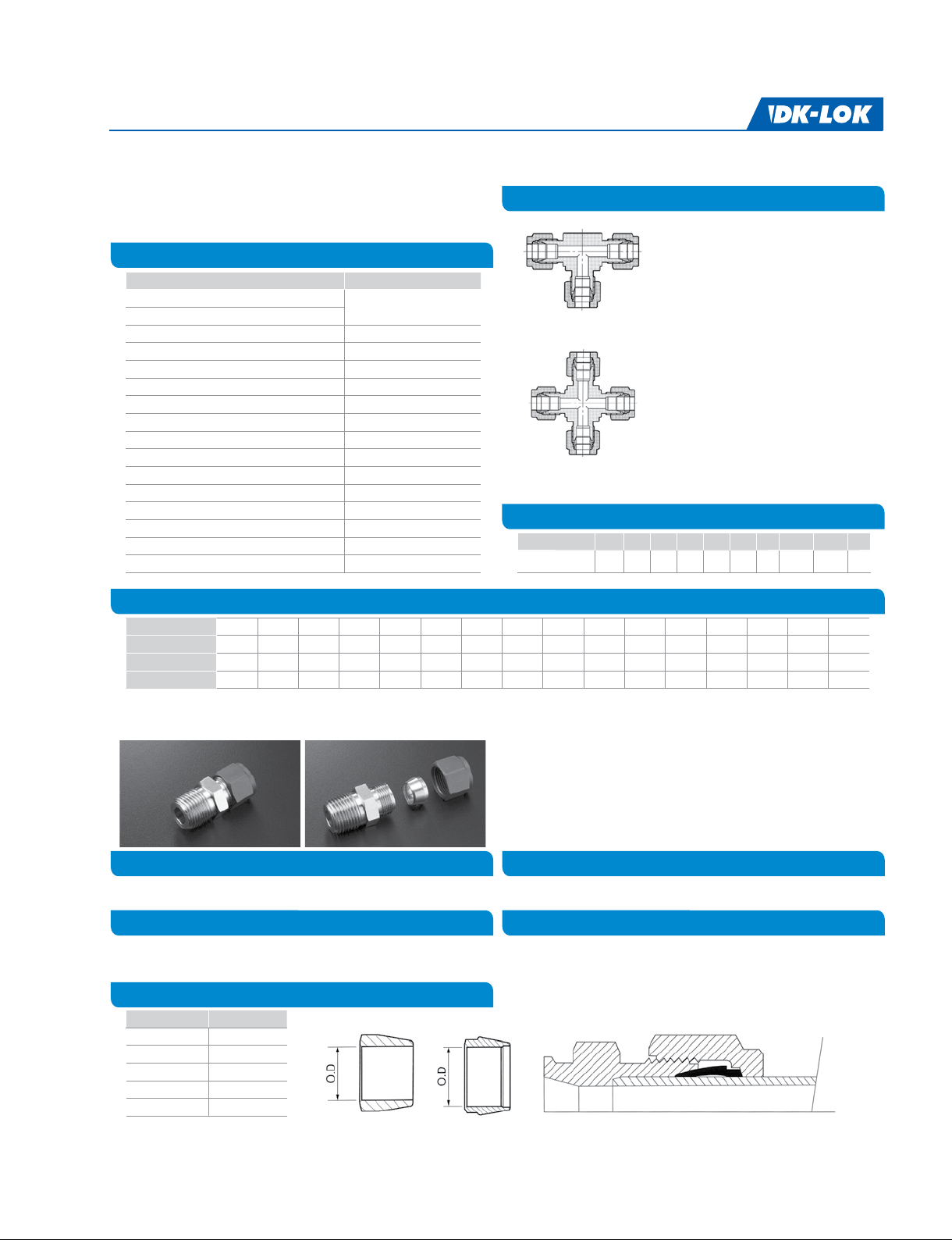
Ordering Information
Tee and Cross Fittings
Sux the material designator to the part number. Example: DU-8-S
Table 18. Material Designator
Material Designator
Stainless Steel316
Dual Grade
Brass B
Carbon Steel C
Stainless 310 310
Duplex D
Super Duplex SD
Aluminum AL
Alloy 20 L20
Hastelloy C276 HC
Alloy 400 M
Alloy 600 IN
Alloy 625 L625
Alloy 825 L825
Titanium Gr. 2 TI
PTFE PE
Table 20. Tube O.D. Designator
OD in.
Designator
OD mm
Designator
1/16 1/8 3/16 1/4 5/16 3/8 1/2 5/8 3/4 7/8 1 1 1/4 1 1/2 2
123456810121416202432
2mm 3 mm 4 mm 6 mm 8mm 10 mm 12 mm 16 mm 20 mm 22 mm 25 mm 28 mm 32 mm 38 mm 42 mm 50 mm
2M 3 M 4 M 6 M 8 M 10 M 12 M 16 M 20 M 22 M 25 M 28 M 32 M 38 M 42 M 50 M
S
12
3
4
12
3
Table 19. Pipe Thread Size Designator
Nom. Size in. 1/16 1/8 1/4 3/8 1/2 3/4 1 1-1/4 1-1/2 2
Designator 1 2468121620 2432
Tee tting part number is described
by rst the run (1 and 2) and next the
branch (3).
Cross tting part number is described
by rst the run (1 and 2) and next the
branch (3 and 4)
Z series DK-Lok
DK-Lok Z Series single ferrule tube tting is designed and manufactured
to the highest quality standards.
This tting includes single ferrule with standard DK-Lok tting body
and nut.
To help identify DK-Lok Z series from DK-Lok Tube tting, nut is black
Molybdenum Disulde (MoS) coated.
Material
DK-Lok Z Series single ferrule tube tting is manufactured in stainless
steel316.
Pressure and Temperature Ratings
DK-Lok Z Series ttings are identical to DK-Lok Tube Fittings in
pressure and temperature ratings.
Z Series Ferrule
Part No. Tube O.D.
DFZ-4-S 1/4
DFZ-6-S 3/8
DFZ-8-S 1/2
DFZ-12-S 3/4
DFZ-16-S 1
All dimensions are in millimeters unless otherwise specied and only for reference subject to change.
Dimensions
DK-Lok Z Series ttings are dimensionally identical to DK-Lok Tube
Fittings.
Ordering Information
To order Z series, insert Z in the standard DK-Lok tube tting part
number.
Examples: DUZ-8-S, DMCZ8-8N-S, DNZ-4-S
www.dklok.com
10
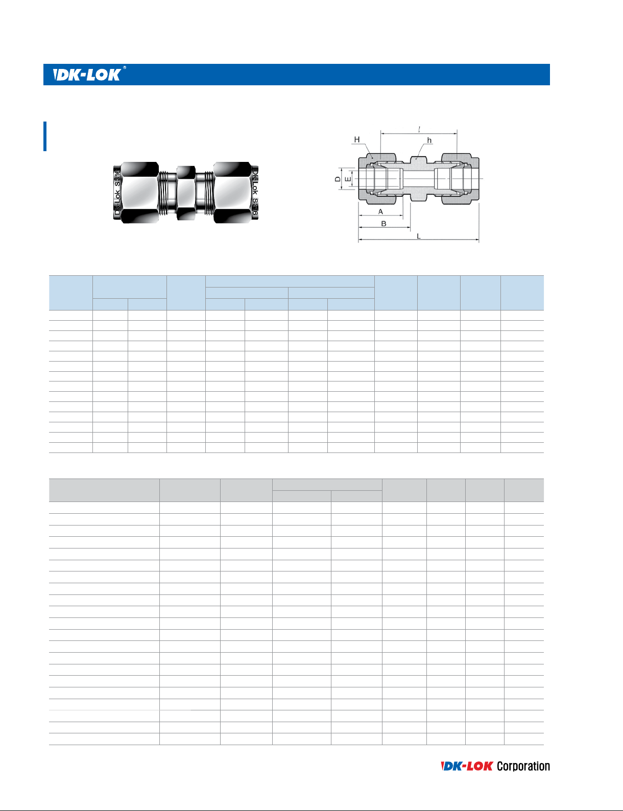
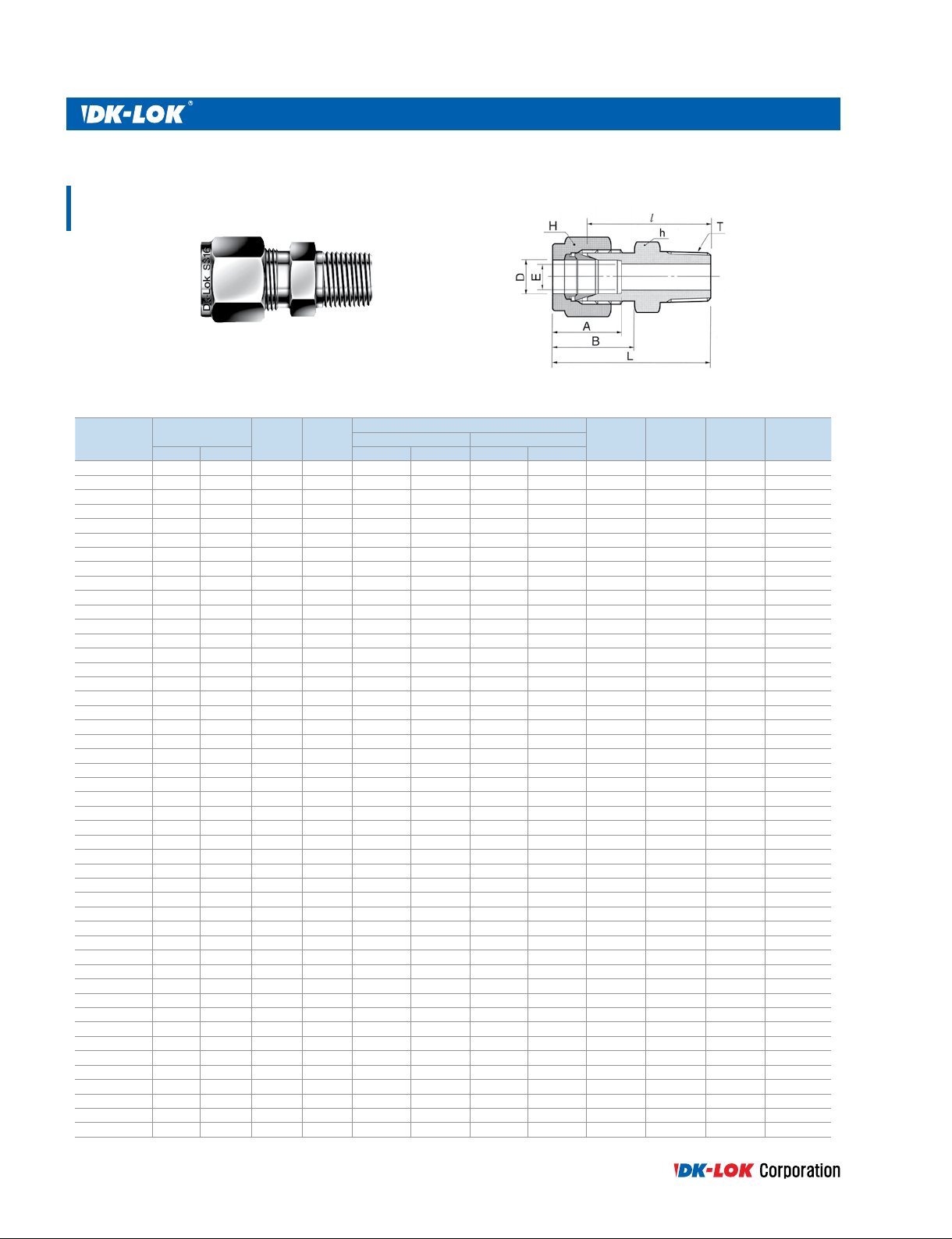
Union
DU
Connects fractional tube
Tube O.D.
Part No.
DU-1 1/16 1.59 1.27 5/16 7.93 5/16 7.93 8.63 10.92 17.50 25.15
DU-2 1/8 3.17 2.28 7/16 11.11 7/16 11.11 12.70 15.24 22.35 35.56
DU-3 3/16 4.76 3.04 7/16 11.11 1/2 12.70 13.71 16.00 24.13 37.33
DU-4 1/4 6.35 4.82 1/2 12.70 9/16 14.28 15.24 17.78 26.16 40.89
DU-5 5/16 7.93 6.35 9/16 14.28 5/8 15.87 16.25 18.54 28.19 42.92
DU-6 3/8 9.52 7.11 5/8 15.87 11/16 17.46 16.76 19.30 30.22 44.95
DU-8 1/2 12.70 10.41 13/16 20.64 7/8 22.22 22.86 21.84 30.98 51.30
DU-10 5/8 15.87 12.70 15/16 23.81 1 25.40 24.38 21.84 31.75 52.07
DU-12 3/4 19.05 15.74 1-1/16 26.98 1-1/8 28.58 24.38 21.84 33.27 53.59
DU-14 7/8 22.22 18.28 1-3/16 30.16 1-1/4 31.75 25.90 21.84 35.05 55.37
DU-16 1 25.40 22.35 1-3/8 34.92 1-1/2 38.10 31.24 26.41 40.38 64.77
DU-20 1-1/4 31.75 27.68 1-3/4 44.45 1-7/8 47.63 41.14 38.86 48.00 92.20
DU-24 1-1/2 38.10 33.90 2-1/8 53.97 2-1/4 57.15 50.03 45.21 53.60 107.95
DU-32 2 50.80 45.97 2-3/4 69.85 3 76.20 67.56 62.73 74.70 149.35
D
in. mm in. mm in. mm
E
Min.
Width across at
AB
NJ
LhH
Connects metric tube
Part No.
DU-2M 2 1.7 12 12 12.9 15.3 22.4 35.6
DU-3M 3 2.4 12 12 12.9 15.3 22.1 35.3
DU-4M 4 2.4 12 12 13.7 16.1 24.1 37.3
DU-6M 6 4.8 14 14 15.3 17.7 26.2 41.0
DU-8M 8 6.4 15 16 16.2 18.6 28.2 43.2
DU-10M 10 7.9 18 19 17.2 19.5 31.0 46.2
DU-12M 12 9.5 22 22 22.8 22.0 31.0 51.2
DU-14M 14 11.1 24 25 24.4 22.0 31.8 52.0
DU-15M 15 11.9 24 25 24.4 22.0 31.8 52.0
DU-16M 16 12.7 24 25 24.4 22.0 31.8 52.0
DU-18M 18 15.1 27 30 24.4 22.0 33.3 53.5
DU-20M 20 15.9 30 32 26.0 22.0 34.8 55.0
DU-22M 22 18.3 30 32 26.0 22.0 34.8 55.0
DU-25M 25 21.8 35 38 31.3 26.5 40.4 65.0
DU-28M 28 21.8 41 46 36.6 36.6 43.4 85.0
DU-30M 30 26.2 46 50 39.7 39.3 49.5 92.9
DU-32M 32 28.6 46 50 42.0 41.6 51.3 97.3
DU-35M 35 31.5 50 55 42.1 41.7 51.3 97.6
DU-38M 38 33.7 55 60 49.4 47.9 58.4 113.6
DU-42M 42 36.8 60 65 49.3 47.8 58.4 113.4
DU-50M 50 45.2 70 76 67.2 62.5 74.7 149
11
Tube O.D.
D
All dimensions are in millimeters unless otherwise specied and only for reference subject to change.
E
Min.
Width across at
hH
AB
NJ
L
DK-Lok Tube Fitting
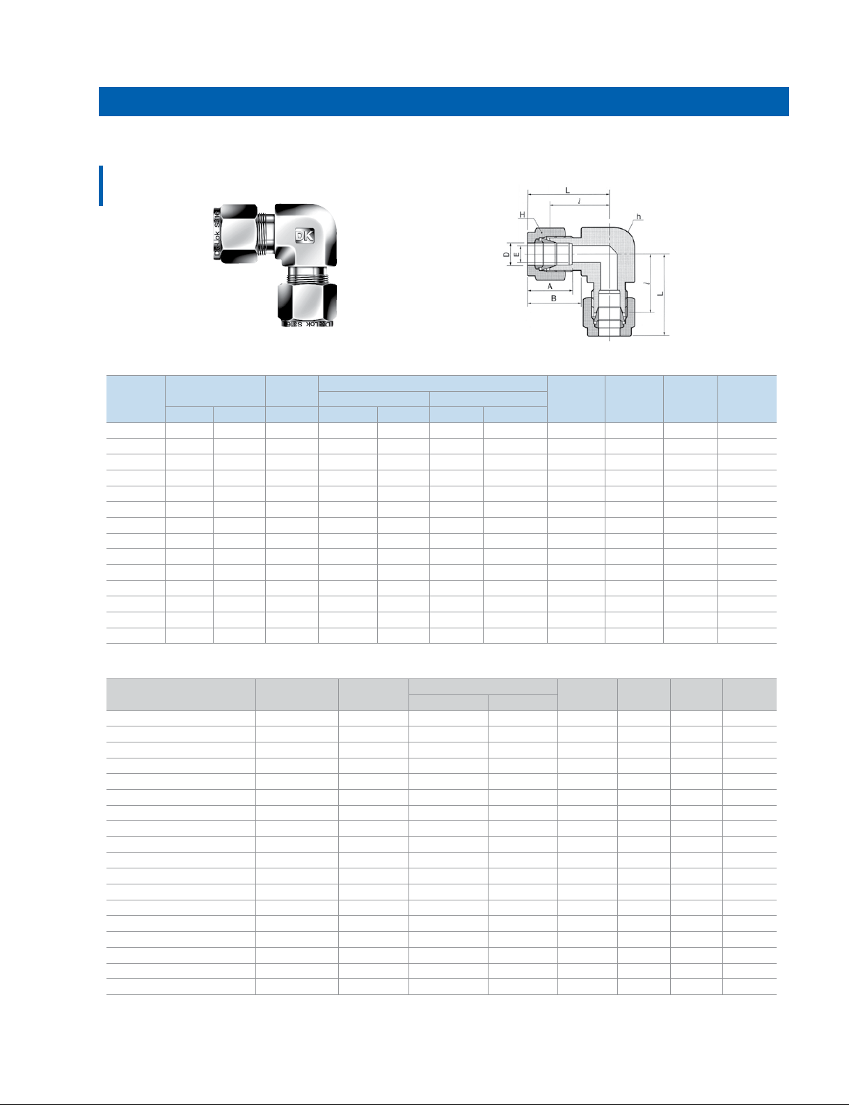
Union Elbow
DL
Connects fractional tube
Tube O.D.
Part No.
DL-1 1/16 1.59 1.27 3/8 9.52 5/16 7.93 8.63 10.92 14.00 17.88
DL-2 1/8 3.17 2.28 3/8 9.52 7/16 11.11 12.70 15.24 15.74 22.35
DL-3 3/16 4.76 3.04 1/2 12.70 1/2 12.70 13.71 16.00 17.78 24.38
DL-4 1/4 6.35 4.82 1/2 12.70 9/16 14.28 15.24 17.78 19.55 26.92
DL-5 5/16 7.93 6.35 9/16 14.28 5/8 15.87 16.25 18.54 21.33 28.70
DL-6 3/8 9.52 7.11 5/8 15.87 11/16 17.46 16.76 19.30 23.11 30.48
DL-8 1/2 12.70 10.41 13/16 20.64 7/8 22.22 22.86 21.84 25.90 36.06
DL-10 5/8 15.87 12.70 15/16 23.81 1 25.40 24.38 21.84 28.70 38.80
DL-12 3/4 19.05 15.74 1-1/16 26.98 1-1/8 28.58 24.38 21.84 29.71 39.87
DL-14 7/8 22.22 18.28 1-3/8 34.92 1-1/4 31.75 25.90 21.84 34.54 44.70
DL-16 1 25.40 22.35 1-3/8 34.92 1-1/2 38.10 31.24 26.41 36.83 49.02
DL-20 1-1/4 31.75 27.68 1-11/16 42.86 1-7/8 47.63 41.14 38.86 44.50 66.54
DL-24 1-1/2 38.10 33.90 2 50.80 2-1/4 57.15 50.03 45.21 50.80 77.97
DL-32 2 50.80 45.97 2-3/4 69.85 3 76.20 67.56 62.73 69.80 107.18
D
in. mm Min. in. mm in. mm
E
Width across at
AB
NJ
LhH
Connects metric tube
Part No.
DL-2M 2 1.7 9.5 12 12.9 15.3 15.7 22.3
DL-3M 3 2.4 9.5 12 12.9 15.3 15.7 22.3
DL-4M 4 2.4 12.7 12 13.7 16.1 18.8 25.4
DL-6M 6 4.8 12.7 14 15.3 17.7 19.6 27.0
DL-8M 8 6.4 14.3 16 16.2 18.6 21.3 28.8
DL-10M 10 7.9 17.5 19 17.2 19.5 23.9 31.5
DL-12M 12 9.5 20.6 22 22.8 22.0 25.9 36.0
DL-15M 15 11.9 25.4 25 24.4 22.0 28.7 38.8
DL-16M 16 12.7 25.4 25 24.4 22.0 28.7 38.8
DL-18M 18 15.1 27.0 30 24.4 22.0 29.7 39.8
DL-20M 20 15.9 34.92 32 26.0 22.0 32.5 42.6
DL-22M 22 18.3 34.92 32 26.0 22.0 32.5 42.6
DL-25M 25 21.8 34.92 38 31.3 26.5 36.8 49.1
DL-28M 28 21.8 41.0 46 36.6 36.6 43.2 64.0
DL-32M 32 28.6 46.0 50 42.0 41.6 49.3 72.3
DL-38M 38 33.7 50.8 60 49.4 47.9 56.4 84.0
DL-42M 42 36.8 60 65 49.3 47.8 55 82.5
DL-50M 50 45.2 70 76 67.2 62.5 69.9 107
All dimensions are in millimeters unless otherwise specied and only for reference subject to change.
Tube O.D.
D
E
Min.
Width across at
hH
AB
www.dklok.com
NJ
L
12
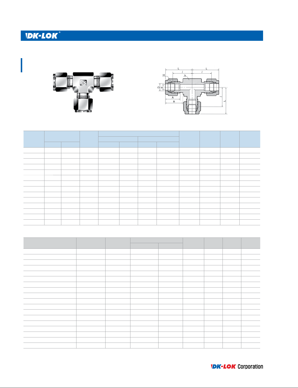
Union Tee
DT
Connects fractional tube
Tube O.D.
Part No.
DT-1 1/16 1.59 1.27 3/8 9.52 5/16 7.93 8.63 10.92 14.00 17.88
DT-2 1/8 3.17 2.28 3/8 9.52 7/16 11.11 12.70 15.24 15.74 22.35
DT-3 3/16 4.76 3.04 1/2 12.70 1/2 12.70 13.71 16.00 17.78 24.38
DT-4 1/4 6.35 4.82 1/2 12.70 9/16 14.28 15.24 17.78 19.55 26.92
DT-5 5/16 7.93 6.35 9/16 14.28 5/8 15.87 16.25 18.54 21.33 28.70
DT-6 3/8 9.52 7.11 5/8 15.87 11/16 17.46 16.76 19.30 23.11 30.48
DT-8 1/2 12.70 10.41 13/16 20.64 7/8 22.22 22.86 21.84 25.90 36.06
DT-10 5/8 15.87 12.70 15/16 23.81 1 25.40 24.38 21.84 28.70 38.80
DT-12 3/4 19.05 15.74 1-1/16 26.98 1-1/8 28.58 24.38 21.84 29.71 39.87
DT-14 7/8 22.22 18.28 1-3/8 34.92 1-1/4 31.75 25.90 21.84 34.54 44.70
DT-16 1 25.40 22.35 1-3/8 34.92 1-1/2 38.10 31.24 26.41 36.83 49.02
DT-20 1-1/4 31.75 27.68 1-11/16 42.86 1-7/8 47.63 41.14 38.86 44.50 66.54
DT-24 1-1/2 38.10 33.90 2 50.80 2-1/4 57.15 50.03 45.21 50.80 77.97
DT-32 2 50.80 45.97 2-3/4 69.85 3 76.20 67.56 62.73 69.80 107.18
D
in. mm in. mm in. mm
E
Min.
Width across at
AB
NJ
LhH
Connects metric tube
Part No.
DT-2M 2 1.7 9.5 12 12.9 15.3 15.7 22.3
DT-3M 3 2.4 9.5 12 12.9 15.3 15.7 22.3
DT-4M 4 2.4 12.7 12 13.7 16.1 18.8 25.4
DT-6M 6 4.8 12.7 14 15.3 17.7 19.6 27.0
DT-8M 8 6.4 14.3 16 16.2 18.6 21.3 28.8
DT-10M 10 7.9 17.5 19 17.2 19.5 23.9 31.5
DT-12M 12 9.5 20.6 22 22.8 22.0 25.9 36.0
DT-15M 15 11.9 25.4 25 24.4 22.0 28.7 38.8
DT-16M 16 12.7 25.4 25 24.4 22.0 28.7 38.8
DT-18M 18 15.1 27.0 30 24.4 22.0 29.7 39.8
DT-20M 20 15.9 34.92 32 26.0 22.0 32.5 42.6
DT-22M 22 18.3 34.92 32 26.0 22.0 32.5 42.6
DT-25M 25 21.8 34.92 38 31.3 26.5 36.8 49.1
DT-28M 28 21.8 41.0 46 36.6 36.6 43.2 64.0
DT-32M 32 28.6 46.0 50 42.0 41.6 49.3 72.3
DT-38M 38 33.7 50.8 60 49.4 47.9 56.4 84.0
DT-42M 42 36.8 60 65 49.3 47.2 55 82.5
DT-50M 50 45.2 70 76 67.2 62.5 69.9 107
13
Tube O.D.
D
All dimensions are in millimeters unless otherwise specied and only for reference subject to change.
E
Min.
Width across at
hH
AB
NJ
L
DK-Lok Tube Fitting
Union Cross
DX
Note : Cross may be made out of bar stock.
Connects fractional tube
Tube O.D.
Part No.
DX-1 1/6 1.59 1.27 3/8 9.52 5/16 7.93 8.63 10.92 14.00 17.88
DX-2 1/8 3.17 2.28 3/8 9.52 7/16 11.11 12.70 15.24 15.74 22.35
DX-3 3/16 4.76 3.04 1/2 12.70 1/2 12.70 13.71 16.00 17.78 24.38
DX-4 1/4 6.35 4.82 1/2 12.70 9/16 14.28 15.24 17.78 19.55 26.92
DX-5 5/16 7.93 6.35 9/16 14.28 5/8 15.87 16.25 18.54 21.33 28.70
DX-6 3/8 9.52 7.11 5/8 15.87 11/16 17.46 16.76 19.30 23.11 30.48
DX-8 1/2 12.70 10.41 13/16 20.64 7/8 22.22 22.86 21.84 25.90 36.06
DX-10 5/8 15.87 12.70 15/16 23.81 1 25.40 24.38 21.84 28.70 38.80
DX-12 3/4 19.05 15.74 1-1/16 26.98 1-1/8 28.58 24.38 21.84 29.71 39.87
DX-14 7/8 22.22 18.28 1-3/8 34.92 1-1/4 31.75 25.90 21.84 34.54 44.70
DX-16 1 25.40 22.35 1-3/8 34.92 1-1/2 38.10 31.24 26.41 36.83 49.02
DX-20 1-1/4 31.75 27.68 1-11/16 42.86 1-7/8 47.63 41.14 38.86 44.50 66.54
DX-24 1-1/2 38.10 33.90 2 50.80 2-1/4 57.15 50.03 45.21 50.80 77.97
DX-32 2 50.80 45.97 2-3/4 69.85 3 76.20 67.56 62.73 69.80 107.18
D
in. mm in. mm in. mm
E
Min.
Width across at
AB
NJ
LhH
Connects metric tube
Part No.
DX-3M 3 2.4 9.5 12 12.9 15.3 15.7 22.3
DX-4M 4 2.4 12.7 12 13.7 16.1 18.8 25.4
DX-6M 6 4.8 12.7 14 15.3 17.7 19.6 27.0
DX-8M 8 6.4 14.3 16 16.2 18.6 21.3 28.8
DX-10M 10 7.9 17.5 19 17.2 19.5 23.9 31.5
DX-12M 12 9.5 20.6 22 22.8 22.0 25.9 36.0
DX-15M 15 11.9 25.4 25 24.4 22.0 28.7 38.8
DX-16M 16 12.7 25.4 25 24.4 22.0 28.7 38.8
DX-18M 18 15.1 27.0 30 24.4 22.0 29.7 39.8
DX-20M 20 15.9 34.92 32 26.0 22.0 32.5 42.6
DX-22M 22 18.3 34.92 32 26.0 22.0 32.5 42.6
DX-25M 25 21.8 34.92 38 31.3 26.5 36.8 49.1
DX-28M 28 21.8 41.0 46 36.6 36.6 43.2 64.0
DX-32M 32 28.6 46.0 50 42.0 41.6 49.3 72.3
DX-38M 38 33.7 50.8 60 49.4 47.9 56.4 84.0
All dimensions are in millimeters unless otherwise specied and only for reference subject to change.
Tube O.D.
D
E
Min.
Width across at
hH
www.dklok.com
AB
NJ
L
14
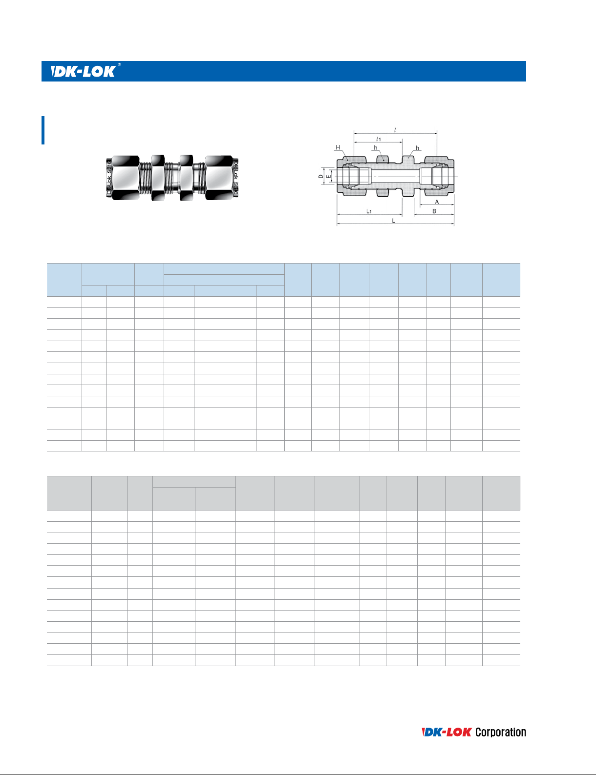
Bulkhead Union
DUB
Connects fractional tube
Tube O.D.
Part No.
DUB-1 1/16 1.59 1.27 5/16 7.93 5/16 7.93 8.63 10.92 23.87 13.46 31.50 17.27 5.16 3.05
DUB-2 1/8 3.17 2.28 1/2 12.70 7/16 11.11 12.70 15.24 38.10 24.63 51.30 31.24 8.33 12.70
DUB-3 3/16 4.76 3.04 9/16 14.28 1/2 12.70 13.71 16.00 40.38 25.40 53.59 32.00 9.92 12.70
DUB-4 1/4 6.35 4.82 5/8 15.87 9/16 14.28 15.24 17.78 42.92 26.16 57.65 33.52 11.50 10.16
DUB-5 5/16 7.93 6.35 11/16 17.46 5/8 15.87 16.25 18.54 45.97 28.44 60.70 35.81 13.09 11.17
DUB-6 3/8 9.52 7.11 3/4 19.05 11/16 17.46 16.76 19.30 47.49 29.46 62.23 36.83 14.68 11.17
DUB-8 1/2 12.70 10.41 15/16 23.81 7/8 22.22 22.86 21.84 50.80 31.75 71.12 41.91 19.44 12.70
DUB-10 5/8 15.87 12.70 1-1/16 26.98 1 25.40 24.38 21.84 52.32 32.51 72.64 42.67 22.62 12.70
DUB-12 3/4 19.05 15.74 1-3/16 30.16 1-1/8 28.58 24.38 21.84 58.67 37.33 78.99 47.49 25.79 16.76
DUB-14 7/8 22.22 18.28 1-3/8 34.92 1-1/4 31.75 25.90 21.84 64.26 42.92 84.58 53.08 28.97 19.05
DUB-16 1 25.40 22.35 1-5/8 41.27 1-1/2 38.10 31.24 26.41 71.37 45.21 95.75 57.40 33.73 19.05
DUB-20 1-1/4 31.75 27.68 1-7/8 47.63 1-7/8 47.63 41.14 38.86 78.99 47.75 123.19 69.85 41.67 19.05
DUB-24 1-1/2 38.10 33.90 2-1/4 57.15 2-1/4 57.15 50.03 45.21 84.83 49.27 139.19 76.45 49.61 19.05
DUB-32 2 50.80 45.97 2-3/4 69.85 3 76.20 67.56 62.73 105.66 56.38 180.34 93.72 57.94 19.05
D
in. mm Min. in. mm in. mm
E
Width across at
hH
AB
NJNJ1
LL1
Panel
Hole
Drill size
Thickness
Panel
Max
Connects metric tube
Part No.
DUB-3M 3 2.4 14 12 12.9 15.3 38.1 24.6 51.3 31.2 8.3 12.7
DUB-4M 4 2.4 14 12 13.7 16.1 40.4 25.4 53.6 32.0 9.9 12.7
DUB-6M 6 4.8 16 14 15.3 17.7 42.9 26.2 57.7 33.6 11.5 10.2
DUB-8M 8 6.4 18 16 16.2 18.6 46.0 28.6 61.0 36.1 13.1 11.2
DUB-10M 10 7.9 22 19 17.2 19.5 48.5 29.4 63.7 37.0 16.2 11.2
DUB-12M 12 9.5 24 22 22.8 22.0 50.8 31.8 71.0 41.9 19.5 12.7
DUB-15M 15 11.9 27 25 24.4 22.0 52.3 32.5 72.5 42.6 22.8 12.7
DUB-16M 16 12.7 27 25 24.4 22.0 52.3 32.5 72.5 42.6 22.8 12.7
DUB-18M 18 15.1 30 30 24.4 22.0 58.7 37.3 78.9 47.4 26.0 16.8
DUB-20M 20 15.9 35 32 26.0 22.0 64.3 42.9 84.5 53.0 29.0 17.0
DUB-22M 22 18.3 35 32 26.0 22.0 64.3 42.9 84.5 53.0 29.0 19.0
DUB-25M 25 21.8 41.3 38 31.3 26.5 71.4 45.2 95.9 57.5 33.7 19.0
DUB-32M 32 28.6 50 50 42.0 41.6 82.3 49.5 128.3 72.5 42.5 19.0
DUB-38M 38 33.7 60 60 49.4 47.9 89.4 51.5 144.6 79.1 50.5 19.0
15
Tube O.D.DE
Min.
All dimensions are in millimeters unless otherwise specied and only for reference subject to change.
Width across at
hH
AB
NJNJ1
LL1
Panel
Hole
Drill size
Panel
Max
Thickness
DK-Lok Tube Fitting
Bulkhead Retainer
DBR
Bulkhead retainer acts as a backup wrench on panel construction.
This allows one person to tighten the jam nut on port A side and
following tubing connection on port A and B without a backup
wrench.
Connects fractional tube
Part No.
DBR-1-S 1/6 9.52 7.94 3.18 7.94 3.97 3.97 #6-3/8 31 3.05
DBR-2-S 1/8 12.7 12.7 3.18 10.31 5.55 3.97 #6-3/8 31 3.05
DBR-3-S 3/16 3M,4M 14.28 14.28 3.18 11.90 6.35 3.97 #6-3/8 31 3.05
DBR-4-S 1/4 6M 15.87 15.87 3.18 12.7 7.14 3.97 #6-3/8 31 3.05
DBR-5-S 5/16 17.46 17.46 3.18 14.28 7.94 3.97 #6-3/8 31 3.05
DBR-8M-S 8M 17.46 18.0 3.18 14.28 7.94 3.97 #6-3/8 31 3.05
DBR-6-S 3/8 19.05 19.05 3.18 15.87 8.73 3.97 #6-3/8 31 3.05
DBR-10M-S 10M 23.81 22.0 3.18 19.05 10.31 5.55 #10-1/2 27 3.66
DBR-8-S 1/2 12M 23.81 23.81 3.18 19.05 10.31 5.55 #10-1/2 27 3.66
DBR-10-S 5/8 15M,16M 25.4 26.98 3.18 20.64 10.31 5.55 #10-1/2 27 3.66
DBR-12-S 3/4 18M 26.98 30.16 3.18 23.02 11.90 5.55 #10-1/2 27 3.66
DBR-14-S 7/8 28.57 33.33 3.18 26.19 13.49 5.55 #10-1/2 27 3.66
DBR-16-S 1 32.54 41.27 3.18 29.37 14.28 5.55 #10-1/2 27 3.66
DK-Lok O.D.
in. mm
A B C D E F “U” Drive Screw
Drill
Number
Drill Holl
Dia
Bulkhead Elbow Union
DBL
Connects Metic tube
Part No.
DBL-6M 6 4.8 15.8 14.2 14.0 15.3 17.7 36.5 20.6 43.9 30.0 11.5 10.2
DBL-8M 8 6.4 17.4 17.4 16.0 18.6 46.0 40.9 23.2 48.4 30.7 13.1 11.2
DBL-10M 10 7.9 22.0 22.0 19.0 19.5 48.5 44.5 26.9 52.1 34.5 16.2 11.2
DBL-12M 12 9.5 24.0 23.8 22.0 22.0 50.8 46.9 26.9 57.0 37.0 19.5 12.7
DBL-16M 16 13.5 27.0 27.0 25.0 22.0 52.3 53.5 34.1 63.7 44.5 22.8 12.7
DBL-20M 20 15.9 34.9 35.0 32.0 26.0 22.0 68.4 39.0 78.2 48.7 29.0 17.0
DBL-25M 25 21.8 41.0 41.0 38.0 31.3 26.5 74.2 46.1 86.5 58.4 33.7 19.1
All dimensions are in millimeters unless otherwise specied and only for reference subject to change.
Tube O.D.
mm h h
Min.
E
Width across at
1 H
AB
NJNJ1
www.dklok.com
LL1
Panel Hole
Drill size
Panel Max
Thickness
16
Reducing Union
DUR
Connects fractional tube
Part No.
Tube O.D.
in. mm in. mm in. mm in. mm in. mm
DUR2-1 1/8 3.18 1/16 1.59 1.27 7/16 11.11 7/16 11.11 5/16 7.93 12.70 8.63 15.24 10.92 20.60 30.91
DUR3-1 3/16 4.76 1/16 1.59 1.27 7/16 11.11 1/2 12.70 5/16 7.93 13.71 8.63 16.00 10.92 21.84 32.25
DUR3-2 3/16 4.76 1/8 3.17 2.28 7/16 11.11 1/2 12.70 7/16 11.11 13.71 12.70 16.00 15.24 23.36 36.57
DUR4-1 1/4 6.35 1/16 1.59 1.27 1/2 12.70 9/16 14.28 5/16 7.93 15.24 8.63 17.78 10.92 23.11 34.29
DUR4-2 1/4 6.35 1/8 3.17 2.28 1/2 12.70 9/16 14.28 7/16 11.11 15.24 12.70 17.78 15.24 24.63 38.60
DUR4-3 1/4 6.35 3/16 4.76 3.04 1/2 12.70 9/16 14.28 1/2 12.70 15.24 13.71 17.78 16.00 25.40 39.37
DUR5-2 5/16 7.93 1/8 3.17 2.28 9/16 14.28 5/8 15.87 7/16 11.11 16.25 12.70 18.54 15.24 25.90 39.87
DUR5-4 5/16 7.93 1/4 6.35 4.82 9/16 14.28 5/8 15.87 9/16 14.28 16.25 15.24 18.54 17.78 27.43 42.16
DUR6-1 3/8 9.52 1/16 1.59 1.27 5/8 15.87 11/16 17.46 5/16 7.93 16.76 8.63 19.30 10.92 25.40 36.57
DUR6-2 3/8 9.52 1/8 3.17 2.28 5/8 15.87 11/16 17.46 7/16 11.11 16.76 12.70 19.30 15.24 26.92 40.89
DUR6-4 3/8 9.52 1/4 6.35 4.82 5/8 15.87 11/16 17.46 9/16 14.28 16.76 15.24 19.30 17.78 28.44 43.18
DUR6-5 3/8 9.52 5/16 7.93 6.35 5/8 15.87 11/16 17.46 5/8 15.87 16.76 16.25 19.30 18.54 29.46 44.19
DUR8-2 1/2 12.70 1/8 3.17 2.28 13/16 20.64 7/8 22.22 7/16 11.11 22.86 12.70 21.84 15.24 28.44 45.21
DUR8-4 1/2 12.70 1/4 6.35 4.82 13/16 20.64 7/8 22.22 9/16 14.28 22.86 15.24 21.84 17.78 29.46 46.99
DUR8-6 1/2 12.70 3/8 9.52 7.11 13/16 20.64 7/8 22.22 11/16 17.46 22.86 16.76 21.84 19.30 30.98 48.51
DUR10-6 5/8 15.87 3/8 9.52 7.11 15/16 23.81 1 25.40 11/16 17.46 24.38 16.76 21.84 19.30 31.75 49.27
DUR10-8 5/8 15.87 1/2 12.70 10.41 15/16 23.81 1 25.40 7/8 22.22 24.38 22.86 21.84 21.84 31.75 52.07
DUR12-4 3/4 19.05 1/4 6.35 4.82 1-1/16 26.98 1-1/8 28.57 9/16 14.48 24.38 15.24 21.84 17.78 31.75 49.27
DUR12-6 3/4 19.05 3/8 9.52 7.11 1-1/16 26.98 1-1/8 28.57 11/16 17.46 24.38 16.76 21.84 19.30 33.27 50.80
DUR12-8 3/4 19.05 1/2 12.70 10.41 1-1/16 26.98 1-1/8 28.57 7/8 22.22 24.38 22.86 21.84 21.84 33.27 53.59
DUR12-10 3/4 19.05 5/8 15.87 12.70 1-1/16 26.98 1-1/8 28.57 1 25.40 24.38 24.38 21.84 21.84 33.27 53.59
DUR16-8 1 25.40 1/2 12.70 10.41 1-3/8 34.92 1-1/2 38.10 7/8 22.22 31.24 22.86 26.41 21.84 40.89 63.24
DUR16-12 1 25.40 3/4 19.05 15.74 1-3/8 34.92 1-1/2 38.10 1-1/8 28.58 31.24 24.38 26.41 21.84 40.38 62.73
E
Min.
Connects metric tube
Part No.
DUR3M-2M 3 2 1.7 12 12 12 12.9 12.9 15.3 15.3 22.1 35.3
DUR6M-2M 6 2 1.7 14 14 12 15.3 12.9 17.7 15.3 24.6 38.6
DUR6M-3M 6 3 2.4 14 14 12 15.3 12.9 17.7 15.3 24.6 38.6
DUR6M-4M 6 4 2.4 14 14 12 15.3 13.7 17.7 16.1 25.4 39.4
DUR8M-6M 8 6 4.8 15 16 14 16.2 15.3 18.6 17.7 27.4 42.3
DUR10M-3M 10 3 2.4 18 19 12 17.2 12.9 19.5 15.3 27.7 41.9
DUR10M-4M 10 4 2.4 18 19 12 17.2 13.7 19.5 16.1 28.7 42.9
DUR10M-6M 10 6 4.8 18 19 14 17.2 15.3 19.5 17.7 29.5 44.5
DUR10M-8M 10 8 6.4 18 19 16 17.2 16.2 19.5 18.6 30.0 45.1
DUR12M-6M 12 6 4.8 22 22 14 22.8 15.3 22.0 17.7 29.5 47.0
DUR12M-8M 12 8 6.4 22 22 16 22.8 16.2 22.0 18.6 30.2 47.8
DUR12M-10M 12 10 7.9 22 22 19 22.8 17.2 22.0 19.5 31.0 48.7
DUR15M-12M 15 12 9.8 24 25 22 24.4 17.2 22.0 19.5 31.8 52.5
DUR16M-10M 16 10 7.9 24 25 19 24.4 17.2 22.0 19.5 31.8 49.5
DUR16M-12M 16 12 9.5 24 25 22 24.4 22.8 22.0 22.0 31.8 52.0
DUR18M-10M 18 10 7.9 27 30 19 24.4 17.2 22.0 19.5 33.0 51.0
DUR18M-12M 18 12 9.5 27 30 22 24.4 22.8 22.0 22.0 33.3 53.5
DUR25M-18M 25 18 15.1 35 38 30 31.3 24.4 26.5 22.0 38.6 61.0
DUR25M-20M 25 20 15.9 35 38 32 31.3 26.0 26.5 22.0 39.9 62.3
DUR30M-18M 30 18 15.1 46 50 30 39.7 24.4 39.3 22.0 43.7 75.4
DUR30M-20M 30 20 15.9 46 50 32 39.7 26.0 39.3 22.0 43.7 75.4
DUR30M-25M 30 25 21.8 46 50 38 39.7 31.3 39.3 26.5 46.2 80.1
DUR32M-18M 32 18 15.1 46 50 30 42.0 24.4 41.6 22.0 44.7 77.8
DUR32M-20M 32 20 15.9 46 50 32 42.0 26.0 41.6 22.0 44.7 77.8
DUR32M-25M 32 25 21.8 46 50 38 42.0 31.3 41.6 26.5 47.0 82.3
DUR38M-20M 38 20 15.9 55 60 32 49.4 26.0 47.9 22.0 49.8 87.5
DUR38M-25M 38 25 21.8 55 60 38 49.4 31.3 47.9 26.5 52.1 92.0
DUR38M-30M 30 30 26.2 55 60 50 49.4 39.7 47.9 39.3 55.4 104.6
Tube O.D.
DD
1 hHH1
E
Min.
Width across at
Width across at
1 BB1
AA
AA1 BB1
NJ
NJ
LDD1 hHH1
L
17
All dimensions are in millimeters unless otherwise specied and only for reference subject to change.
DK-Lok Tube Fitting
Reducing Union Elbow
DLR
Connects fractional tube
Tube O.D. Width across at
Part No.
in. mm in. mm in. mm in. mm in. mm
DLR2-1 1/8 3.17 1/16 1.59 3/8 9.52 7/6 11.11 5/16 7.93 2.4 1.3 12.7 8.63 15.24 10.93 15.74 14.2 22.35 18.0
DLR4-2 1/4 635 1/8 3.17 1/2 12.7 9/16 14.28 7/6 11.11 4.8 2.4 15.24 12.7 17.78 15.24 19.55 17.9 26.92 24.5
DLR6-4 3/8 9.52 1/4 6.35 5/8 15.87 11/16 17.46 9/16 14.28 7.1 4.8 16.76 15.24 19.3 17.78 23.1 21.92 30.47 29.29
DLR8-4 1/2 12.7 1/4 6.35 13/16 20.64 7/8 22.22 9/16 14.28 10.41 4.8 22.86 15.24 21.84 17.78 25.9 24.4 36.06 31.77
DLR8-6 1/2 12.7 3/8 9.52 13/16 20.64 7/8 22.22 11/16 17.46 10.41 7.1 22.86 16.76 21.84 19.30 25.9 25.9 36.06 33.27
Connects metric tube
Tube O.D. Width across at
Part No.
DLR8M-4 8 1/4 6.35 9/16 14.28 16 9/16 14.28
D
D
1 hHH1
in. mm in. mm mm in. mm
EE1 AA1 BB1
EE1 AA1 BB1
6.4 4.8 16.2 15.24 18.6 17.78 21.3 20.6 28.7 28.0
NJNJ1
NJNJ1
LL1DD1 hHH1
LL1
Reducing Union Cross
DXR
Connects fractional tube
Port 1 Por t 2 Port3 Port4
Part No.
in. mm in. mm in. mm in. mm in. mm
DXR12-12-6-6 3/4 19.05 3/8 9.52 7.1 1-1/16 26.98 1-1/8 28.57 11/16 17.46 24.38 16.76 21.84 19.3 29.71 29.71 39.87 37.07
E
Min.
Connects metric tube
Port 2 Port3 Port4
Part No.
DXR16M-6M-6M-6M 16 6 4.8 25.4 25 14 24.4 15.3 22.0 17.7 28.7 27.2 38.8 34.6
Port 1
D
D1 hHH1
E
Min.
Width across at
Width across at
AA1 BB1
1 BB1
AA
NJNJ1
NJNJ1
LL1DD1 hHH1
LL1
All dimensions are in millimeters unless otherwise specied and only for reference subject to change.
www.dklok.com
18
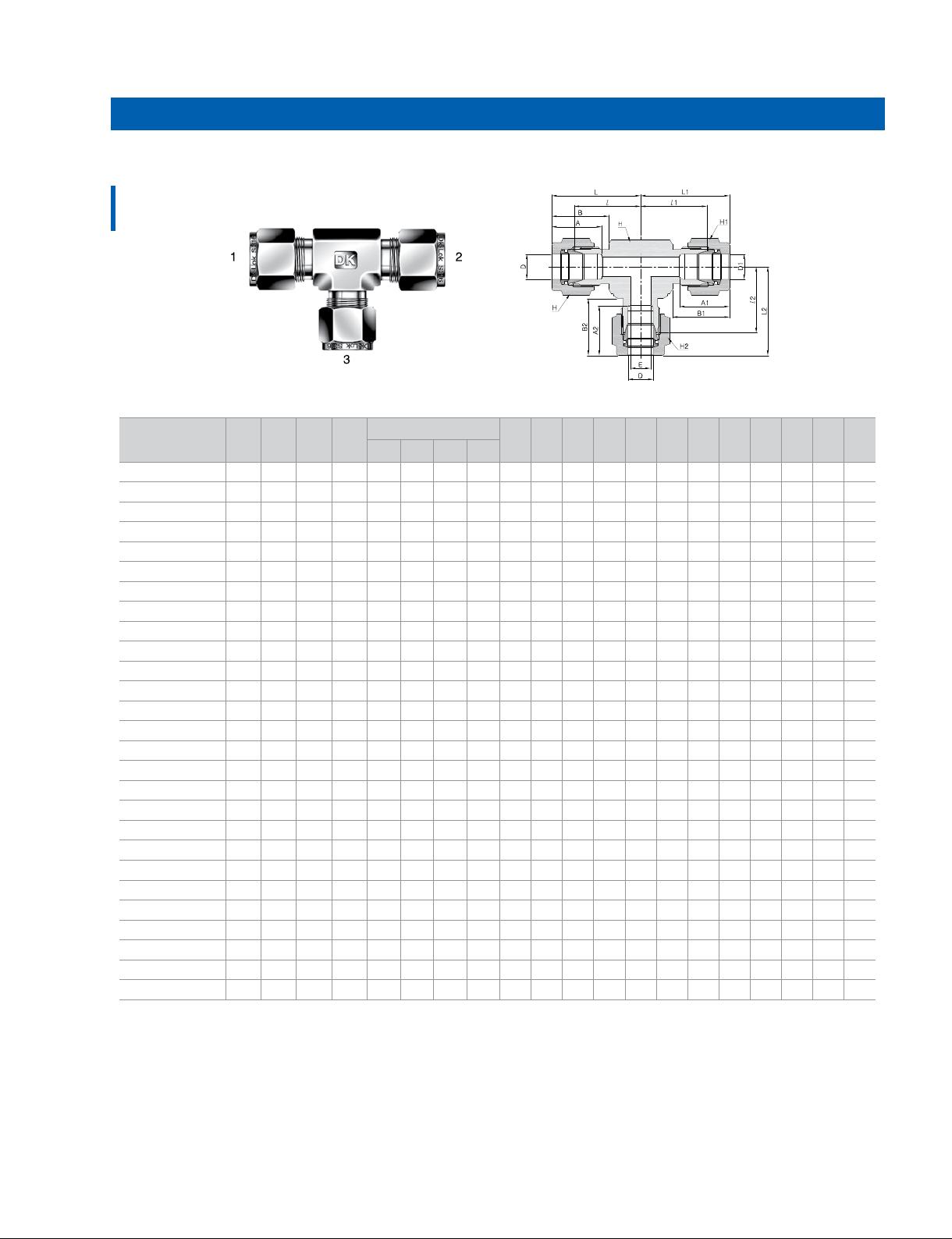
Reducing Union Tee
DTR
Connects fractional tube
Part No
DTR4-4-2
DTR4-4-6
DTR4-8-8
DTR6-4-6
DTR6-6-4
DTR6-6-8
DTR8-4-6
DTR8-4-8
DTR8-6-6
DTR8-8-4
DTR8-8-6
DTR10-10-6
DTR12-8-12
DTR12-12-4
DTR12-12-6
DTR12-12-8
DTR12-12-16
DTR12-12-20
DTR14-14-8
DTR16-12-12
DTR16-16-4
DTR16-16-6
DTR16-16-8
DTR16-16-12
DTR20-12-12
DTR20-20-12
DTR24-20-20
DTR24-24-8
DTR24-24-12
DTR24-24-16
Port 1 DPort 2
in. mm in. mm in. mm in. mm in. mm in. mm in. mm
1/4 6.35 1/4 6.35 1/8 3.17 2.4 15.24 15.24 12.7 17.78 17.78 15.24 1/2 12.7 9/16 14.28 9/16 14.28 7/16 11.11 19.55 19.55 17.9 26.91 26.91 24.5
1/4 6.35 1/4 6.35 3/8 9.52 4.8 15.24 15.24 16.76 17.78 17.78 19.3 5/8 15.87 9/16 14.28 9/16 14.28 11/16 17.46 21.92 21.92 23.1 29.28 29.28 30.46
1/4 6.35 1/2 12.7 1/2 12.7 4.8 15.24 22.86 22.86 17.78 21.84 21.84 13/16 20.64 9/16 14.28 7/8 22.22 7/8 22.22 24.4 25.9 25.9 31.76 36.06 36.06
3/8 9.52 1/4 6.35 3/8 9.52 4.8 16.76 15.24 16.76 19.3 17.78 19.3 5/8 15.87 11/16 17.46 9/16 14.28 11/16 17.46 23.1 21.92 23.1 30.46 29.28 30.46
3/8 9.52 3/8 9.52 1/4 6.35 4.8 16.76 16.76 15.24 19.3 19.3 17.78 5/8 15.87 11/16 17.46 11/16 17.46 9/16 14.28 23.1 23.1 21.92 30.46 30.46 29.28
3/8 9.52 3/8 9.52 1/2 12.7 7.1 16.76 16.76 22.86 19.3 19.3 21.84 13/16 20.64 11/16 17.46 11/16 17.46 7/8 22.22 25.9 25.9 25.9 33.26 33.26 36.06
1/2 12.7 1/4 6.35 3/8 9.52 4.8 22.86 15.24 16.76 21.84 17.78 19.3 13/16 20.64 7/8 22.22 9/16 14.28 11/16 17.46 25.9 25.9 25.9 36.06 33.26 33.26
1/2 12.7 1/4 6.35 1/2 12.7 7.1 22.86 15.24 22.86 21.84 17.78 21.84 13/16 20.64 7/8 22.22 9/16 14.28 7/8 22.22 25.9 24.4 25.9 36.06 31.76 36.06
1/2 12.7 3/8 9.52 3/8 9.52 7.1 22.86 16.76 16.76 21.84 19.3 19.3 13/16 20.64 7/8 22.22 11/16 17.46 11/16 17.46 25.9 25.9 25.9 36.06 33.26 33.26
1/2 12.7 1/2 12.7 1/4 6.35 4.8 22.86 22.86 15.24 21.84 21.84 17.78 13/16 20.64 7/8 22.22 7/8 22.22 9/16 14.28 25.9 25.9 24.4 36.06 36.06 31.76
1/2 12.7 1/2 12.7 3/8 9.52 7.1 22.86 22.86 16.76 21.84 21.84 19.3 13/16 20.64 7/8 22.22 7/8 22.22 11/16 17.46 25.9 25.9 25.9 36.06 36.06 33.26
5/8 15.87 5/8 15.87 3/8 9.52 7.1 24.38 24.38 16.76 21.84 21.84 19.3 15/16 23.81 1 25.4 1 25.4 11/16 17.46 28.7 28.7 28.7 38.86 38.86 36.06
3/4 19.05 1/2 12.7 3/4 19.05 10.41 24.38 22.86 24.38 21.84 21.84 21.84 1-1/16 26.98 1-1/8 28.57 7/8 22.22 1-1/8 28.57 29.71 29.71 29.71 39.87 39.87 39.87
3/4 19.05 3/4 19.05 1/4 6.35 4.8 24.38 24.38 15.24 21.84 21.84 17.78 1-1/16 26.98 1-1/8 28.57 1-1/8 28.57 9/16 14.28 29.71 29.71 28.21 39.87 39.87 35.57
3/4 19.05 3/4 19.05 3/8 9.52 7.1 24.38 24.38 16.76 21.84 21.84 19.3 1-1/16 26.98 1-1/8 28.57 1-1/8 28.57 11/16 17.46 29.71 29.71 29.71 39.87 39.87 35.57
3/4 19.05 3/4 19.05 1/2 12.7 10.41 24.38 24.38 22.86 21.84 21.84 21.84 1-1/16 26.98 1-1/8 28.57 1-1/8 28.57 7/8 22.22 29.71 29.71 29.71 39.87 39.87 38.37
3/4 19.05 3/4 19.05 1 25.4 16.0 24.38 24.38 31.24 21.84 21.84 26.41 1-3/8 34.92 1-1/8 28.57 1-1/8 28.57 1-1/2 38.10 34.43 34.43 36.83 49.02 49.02 45.7
3/4 19.05 3/4 19.05 1-1/4 31.75 16.0 24.38 24.38 41.14 21.84 21.84 38.86 1-11/16 42.86 1-1/8 28.57 1-1/8 28.57 1-7/8 47.63 39.41 39.41 44.45 49.57 49.57 66.55
7/8 22.22 7/8 22.22 1/2 12.7 10.41 25.9 25.9 22.86 21.84 21.84 21.84 1-1/4 31.75 1-1/4 31.75 1-1/4 31.75 7/8 22.22 34.54 34.54 34.54 44.7 44.7 44.7
1 25.4 3/4 19.05 3/4 19.05 16.0 31.24 24.38 24.38 26.41 21.84 21.84 1-3/8 34.92 1-1/2 38.10 1-1/8 28.57 1-1/8 28.57 36.83 35.54 35.54 49.02 45.7 45.7
1 25.4 1 25.4 1/4 6.35 4.8 31.24 31.24 15.24 26.41 26.41 17.78 1-3/8 34.92 1-1/2 38.10 1-1/2 38.10 9/16 14.28 36.83 36.83 33.04 49.02 49.02 40.4
1 25.4 1 25.4 3/8 9.52 7.1 31.24 31.24 16.76 26.41 26.41 19.3 1-3/8 34.92 1-1/2 38.10 1-1/2 38.10 11/16 17.46 36.83 36.83 34.54 49.02 49.02 41.9
1 25.4 1 25.4 1/2 12.7 10.41 31.24 31.24 22.86 26.41 26.41 21.84 1-3/8 34.92 1-1/2 38.10 1-1/2 38.10 7/8 22.22 36.83 36.83 34.54 49.02 49.02 44.7
1 25.4 1 25.4 3/4 19.05 16.0 31.24 31.24 24.38 26.41 26.41 21.84 1-3/8 34.92 1-1/2 38.10 1-1/2 38.10 1-1/8 28.57 36.83 36.83 35.54 49.02 49.02 45.7
1 1/4 31.75 3/4 19.05 3/4 19.05 16.0 41.14 24.38 24.38 38.86 21.84 21.84 1-11/16 42.86 1-7/8 47.63 1-1/8 28.57 1-1/8 28.57 44.45 39.41 39.41 66.55 49.57 49.57
1 1/4 31.75 1 1/4 31.75 3/4 19.05 16.0 41.14 41.14 24.38 38.86 38.86 21.84 1-11/16 42.86 1-7/8 47.63 1-7/8 47.63 1-1/8 28.57 44.45 44.45 39.41 66.55 66.55 49.57
1 1/2 38.10 1 1/4 31.75 1 1/4 31.75 27.69 50.03 41.14 41.14 45.21 38.86 38.86 2 50.8 2-1/4 57.15 1-7/8 47.63 1-7/8 47.63 50.8 49.62 49.62 77.97 71.72 71.72
1 1/2 38.10 1 1/2 38.10 1/2 12.7 10.41 50.03 50.03 22.86 45.21 45.21 21.84 2 50.8 2-1/4 57.15 2-1/4 57.15 7/8 22.22 50.8 50.8 44.58 77.97 77.97 54.74
1 1/2 38.10 1 1/2 38.10 3/4 19.05 16.0 50.03 50.03 24.38 45.21 45.21 21.84 2 50.8 2-1/4 57.15 2-1/4 57.15 1-1/8 28.57 50.8 50.8 44.58 77.97 77.97 54.74
1 1/2 38.10 1 1/2 38.10 1 25.4 22.3 50.03 50.03 31.24 45.21 45.21 26.41 2 50.8 2-1/4 57.15 2-1/4 57.15 1-1/2 38.10 50.8 50.8 47.75 77.97 77.97 59.94
D
1
Port 3
2
D
E
Min.
1 A2 BB1 B2
AA
Width across at
NJNJ1 NJ2
LL1 L2hHH1 H2
19
All dimensions are in millimeters unless otherwise specied and only for reference subject to change.
DK-Lok Tube Fitting
Reducing Union Tee
DTR
Connects metric tube
Port 3
Part No.
DTR3M-3M-6M 3 3 6 2.4 12.7 12 12 14 12.9 12.9 15.3 15.3 15.3 17.7 18.0 18.0 19.6 24.6 24.6 27.0
DTR8M-8M-6M 8 8 6 4.8 15 16 16 14 16.2 16.2 15.3 18.6 18.6 17.7 21.3 21.3 20.5 28.8 28.8 28.0
DTR10M-10M-6M 10 10 6 4.8 17.4 19 19 14 17.2 17.2 15.3 19.5 19.5 17.7 23.9 23.9 22.4 31.5 31.5 29.8
DTR10M-10M-12M 10 10 12 7.9 20.6 19 19 22 17.2 17.2 22.8 19.5 19.5 22.0 25.9 25.9 25.9 33.5 33.5 36.0
DTR12M-6M-10M 12 6 10 4.8 20.6 22 14 19 22.8 15.3 17.2 22.0 17.7 19.5 25.9 24.4 25.9 36.0 31.8 33.5
DTR12M-6M-12M 12 6 12 4.8 20.6 22 14 22 22.8 15.3 22.8 22.0 17.7 22.0 25.9 24.4 25.9 36.0 31.8 36.0
DTR12M-10M-10M 12 10 10 7.9 20.6 22 19 19 22.8 17.2 17.2 22.0 19.5 19.5 25.9 25.9 25.9 36.0 33.5 33.5
DTR12M-12M-10M 12 12 10 7.9 20.6 22 22 19 22.8 22.8 17.2 22.0 22.0 19.5 25.9 25.9 25.9 36.0 36.0 33.5
DTR12M-12M-6M 12 12 6 4.8 20.6 22 22 14 22.8 22.8 15.3 22.0 22.0 17.7 25.9 25.9 24.4 36.0 36.0 31.8
DTR15M-15M-12M 15 15 12 9.8 25.4 25 25 22 24.4 24.4 22.8 22.0 22.0 22.0 28.7 28.7 28.7 38.8 38.8 38.8
DTR16M-16M-12M 16 16 12 9.8 25.4 25 25 22 24.4 24.4 22.8 22.0 22.0 22.0 28.7 28.7 28.7 38.8 38.8 38.8
DTR18M-18M-12M 18 18 12 9.8 27 30 30 22 24.4 24.4 22.8 22.0 22.0 22.0 29.7 29.7 28.2 39.8 39.8 38.3
DTR20M-12M-20M 20 12 20 9.8 34.9 32 22 32 26.0 22.8 26.0 22.0 22.0 22.0 32.5 32.5 32.5 42.6 42.6 42.6
DTR20M-20M-6M 20 20 6 4.8 34.9 32 32 14 26.0 26.0 15.3 22.0 22.0 17.7 32.5 32.5 31.0 42.6 42.6 38.4
DTR20M-20M-10M 20 20 10 7.9 34.9 32 32 19 26.0 26.0 17.2 22.0 22.0 19.5 32.5 32.5 32.5 42.6 42.6 40.1
DTR20M-20M-12M 20 20 12 9.8 34.9 32 32 22 26.0 26.0 22.8 22.0 22.0 22.0 32.5 32.5 32.5 42.6 42.6 42.6
DTR20M-20M-25M 20 20 25 15.9 34.9 32 32 38 26.0 26.0 31.3 22.0 22.0 26.5 34.3 34.3 36.8 44.4 44.4 49.1
DTR20M-20M-32M 20 20 32 15.9
DTR22M-22M-12M 22 22 12 9.8 34.9 32 32 22 26.0 26.0 22.8 22.0 22.0 22.0 32.5 32.5 32.5 42.6 42.6 42.6
DTR25M-20M-20M 25 20 20 15.9 34.9 38 32 32 31.3 26.0 26.0 26.5 22.0 22.0 36.8 34.3 34.3 49.1 44.4 44.4
DTR25M-25M-10M 25 25 10 7.9 34.9 38 38 19 31.3 31.3 17.2 26.5 26.5 19.5 36.8 36.8 34.3 49.1 49.1 38.9
DTR25M-25M-12M 25 25 12 9.8 34.9 38 38 22 31.3 31.3 22.8 26.5 26.5 22.0 36.8 36.8 34.3 49.1 49.1 44.4
DTR25M-25M-20M 25 25 20 15.9 34.9 38 38 32 31.3 31.3 26.0 26.5 26.5 22.0 36.8 36.8 34.3 49.1 49.1 44.4
DTR32M-32M-20M 32 32 20 15.9 46 38 38 32 42.0 42.0 26.0 41.6 41.6 22.0 49.3 49.3 42.5 72.3 72.3 52.6
DTR38M-32M-32M 38 32 32 28.6 50.8 60 38 38 49.4 42.0 42.0 47.9 41.6 41.6 56.4 54.7 54.7 84.0 77.7 77.7
DTR38M-38M-20M 38 38 20 15.9 50.8 60 60 32 49.4 49.4 26.0 47.9 47.9 22.0 56.4 56.4 47.9 84.0 84.0 58.0
DTR38M-38M-25M 38 38 25 21.8 50.8 60 60 38 49.4 49.4 31.3 47.9 47.9 26.5 56.4 56.4 50.4 84.0 84.0 62.7
Port 1DPort 2
1
D
E
2
D
Min.
Width across at
hHH1 H2
46 32 32 50 26.0 26.0 42.0 22.0 22.0 41.6 42.5 42.5 49.3 52.6 52.6 72.3
AA
1 A2 BB1 B2
NJNJ1 NJ2
LL1 L2
All dimensions are in millimeters unless otherwise specied and only for reference subject to change.
www.dklok.com
20
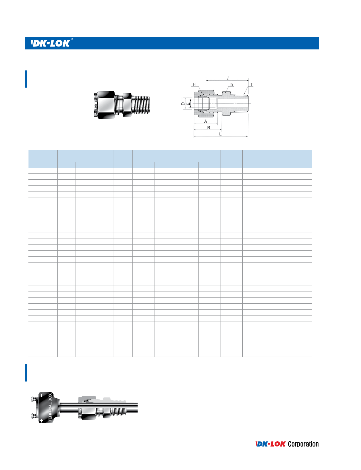
Male Connector
DMC-N
Connects fractional tube to female NPT thread
Tube O.D.
Part No.
DMC1-1N 1/16 1.59 1/16 1.27 5/16 7.93 5/16 7.93 8.63 10.92 20.00 23.83
DMC1-2N 1/16 1.59 1/8 1.27 7/16 11.11 5/16 7.93 8.63 10.92 22.35 26.23
DMC1-4N 1/16 1.59 1/4 1.27 9/16 14.28 5/16 7.93 8.63 10.92 27.17 30.98
DMC2-1N 1/8 3.17 1/16 2.28 7/16 11.11 7/16 11.11 12.70 15.24 23.11 29.71
DMC2-2N 1/8 3.17 1/8 2.28 7/16 11.11 7/16 11.11 12.70 15.24 23.87 30.48
DMC2-4N 1/8 3.17 1/4 2.28 9/16 14.28 7/16 11.11 12.70 15.24 28.95 35.56
DMC2-6N 1/8 3.17 3/8 2.28 11/16 17.46 7/16 11.11 12.70 15.24 29.21 35.81
DMC2-8N 1/8 3.17 1/2 2.28 7/8 22.22 7/16 11.11 12.70 15.24 35.56 42.16
DMC3-2N 3/16 4.76 1/8 3.04 7/16 11.11 1/2 12.70 13.71 16.00 24.63 31.24
DMC3-4N 3/16 4.76 1/4 3.04 9/16 14.28 1/2 12.70 13.71 16.00 29.71 36.32
DMC4-1N 1/4 6.35 1/16 4.82 1/2 12.70 9/16 14.28 15.24 17.78 25.40 32.76
DMC4-2N 1/4 6.35 1/8 4.82 1/2 12.70 9/16 14.28 15.24 17.78 25.40 32.76
DMC4-4N 1/4 6.35 1/4 4.82 9/16 14.28 9/16 14.28 15.24 17.78 30.48 37.84
DMC4-6N 1/4 6.35 3/8 4.82 11/16 17.46 9/16 14.28 15.24 17.78 30.98 38.35
DMC4-8N 1/4 6.35 1/2 4.82 7/8 22.22 9/16 14.28 15.24 17.78 37.33 44.70
DMC4-12N 1/4 6.35 3/4 4.82 1-1/16 26.98 9/16 14.28 15.24 17.78 38.86 46.22
DMC5-2N 5/16 7.93 1/8 4.82 9/16 14.28 5/8 15.87 16.25 18.54 26.67 34.03
DMC5-4N 5/16 7.93 1/4 6.35 9/16 14.28 5/8 15.87 16.25 18.54 31.24 38.60
DMC5-6N 5/16 7.93 3/8 6.35 11/16 17.46 5/8 15.87 16.25 18.54 31.75 39.11
DMC5-8N 5/16 7.93 1/2 6.35 7/8 22.22 5/8 15.87 16.25 18.54 38.11 45.60
DMC6-2N 3/8 9.52 1/8 4.82 5/8 15.87 11/16 17.46 16.76 19.30 27.94 35.30
DMC6-4N 3/8 9.52 1/4 7.11 5/8 15.87 11/16 17.46 16.76 19.30 32.51 39.87
DMC6-6N 3/8 9.52 3/8 7.11 11/16 17.46 11/16 17.46 16.76 19.30 32.51 39.87
DMC6-8N 3/8 9.52 1/2 7.11 7/8 22.22 11/16 17.46 16.76 19.30 38.86 46.22
DMC6-12N 3/8 9.52 3/4 7.11 1-1/16 26.98 11/16 17.46 16.76 19.30 40.38 47.75
DMC6-16N 3/8 9.52 1 7.11 1-3/8 34.92 11/16 17.46 16.76 19.30 47.0 54.37
DMC8-2N 1/2 12.70 1/8 4.82 13/16 20.64 7/8 22.22 22.86 21.84 28.70 38.86
DMC8-4N 1/2 12.70 1/4 7.11 13/16 20.64 7/8 22.22 22.86 21.84 33.27 43.43
DMC8-6N 1/2 12.70 3/8 9.65 13/16 20.64 7/8 22.22 22.86 21.84 33.27 43.43
DMC8-8N 1/2 12.70
DMC8-12N 1/2 12.70 3/4 10.41 1-1/16 26.98 7/8 22.22 22.86 21.84 40.38 50.54
DMC8-16N 1/2 12.70 1 10.41 1-3/8 34.92 7/8 22.22 22.86 21.84 46.99 57.15
DMC10-4N 5/8 15.87 1/4 6.35 15/16 23.81 1 25.40 24.38 21.84 33.80 43.96
DMC10-6N 5/8 15.87 3/8 9.65 15/16 23.81 1 25.40 24.38 21.84 34.03 44.19
DMC10-8N 5/8 15.87 1/2 11.93 15/16 23.81 1 25.40 24.38 21.84 38.86 49.02
DMC10-12N 5/8 15.87 3/4 12.70 1-1/16 26.98 1 25.40 24.38 21.84 40.38 50.54
DMC12-6N 3/4 19.05 3/8 9.65 1-1/16 26.98 1-1/8 28.58 24.38 21.84 34.03 44.19
DMC12-8N 3/4 19.05 1/2 11.93 1-1/16 26.98 1-1/8 28.58 24.38 21.84 40.38 50.54
DMC12-12N 3/4 19.05 3/4 15.74 1-1/16 26.98 1-1/8 28.58 24.38 21.84 40.38 50.54
DMC12-16N 3/4 19.05 1 15.74 1-3/8 34.92 1-1/8 28.58 24.38 21.84 46.99 57.15
DMC14-8N 7/8 22.22 1/2 11.9 1-3/16 30.16 1-1/4 31.75 25.90 21.84 40.38 50.54
DMC14-12N 7/8 22.22 3/4 15.74 1-3/16 30.16 1-1/4 31.75 25.90 21.84 40.38 50.54
DMC14-16N 7/8 22.22 1 18.28 1-3/8 34.92 1-1/4 31.75 25.90 21.84 46.99 57.15
DMC16-6N 1 25.40 3/8 9.65 1-3/8 34.92 1-1/2 38.10 31.24 26.41 40.30 52.49
DMC16-8N 1 25.40 1/2 11.93 1-3/8 34.92 1-1/2 38.10 31.24 26.41 45.21 57.40
DMC16-12N 1 25.40 3/4 15.74 1-3/8 34.92 1-1/2 38.10 31.24 26.41 45.21 57.40
DMC16-16N 1 25.40 1 22.35 1-3/8 34.62 1-1/2 38.10 31.24 26.41 50.03 62.23
D
in. mm in. mm in. mm
T
NPTEMin.
1/2 10.41 7/8 22.22 7/8 22.22 22.86 21.84 38.86 49.02
Width across at
AB
NJ
LhH
21
All dimensions are in millimeters unless otherwise specied and only for reference subject to change.
DK-Lok Tube Fitting
Connects fractional tube to female NPT thread
Tube O.D.
Part No.
DMC20-16N 1-1/4 31.75 1 22.35 1-3/4 44.45 1-7/8 47.63 41.14 38.86 55.11 77.21
DMC20-20N 1-1/4 31.75 1-1/4 27.68 1-3/4 44.45 1-7/8 47.63 41.14 38.86 55.11 77.21
DMC20-24N 1-1/4 31.75 1-1/2 27.68 1-3/4 44.45 1-7/8 47.63 41.14 38.86 60.54 82.64
DMC24-16N 1-1/2 38.10 1 22.30 2-1/8 53.98 2-1/4 57.15 50.03 45.21 59.42 86.60
DMC24-20N 1-1/2 38.10 1-1/4 27.68 2-1/8 53.98 2-1/4 57.15 50.03 45.21 59.42 86.60
DMC24-24N 1-1/2 38.10 1-1/2 33.90 2-1/8 53.98 2-1/4 57.15 50.03 45.21 61.72 88.90
DMC24-32N 1-1/2 38.10 2 33.90 2-3/4 69.85 2-1/4 57.15 50.03 45.21 62.42 99.75
DMC32-8N 2 50.80 1/2 11.93 2-3/4 69.85 3 76.20 67.56 62.73 68.40 105.73
DMC32-20N 2 50.80 1-1/4 45.97 2-3/4 69.85 3 76.20 67.56 62.73 71.40 108.73
DMC32-24N 2 50.80 1-1/2 45.97 2-3/4 69.85 3 76.20 67.56 62.73 75.50 112.83
DMC32-32N 2 50.80 2 45.97 2-3/4 69.85 3 76.20 67.56 62.73 76.20 113.53
D
in. mm in. mm in. mm
T
NPTEMin.
Connects metric tube to female NPT thread
Part No.
DMC2M-2N 2 1/8 1.7 12 12 12.9 15.3 23.9 30.5
DMC3M-2N 3 1/8 2.4 12 12 12.9 15.3 23.1 29.7
DMC3M-4N 3 1/4 2.4 14 12 12.9 15.3 29.0 35.6
DMC4M-2N 4 1/8 2.4 12 12 13.7 16.1 24.6 31.2
DMC4M-4N 4 1/4 2.4 14 12 13.7 16.1 29.7 36.3
DMC6M-2N 6 1/8 4.8 14 14 15.3 17.7 25.4 32.8
DMC6M-4N 6 1/4 4.8 14 14 15.3 17.7 30.2 37.6
DMC6M-6N 6 3/8 4.8 18 14 15.3 17.7 31.0 38.4
DMC6M-8N 6 1/2 4.8 22 14 15.3 17.7 37.3 44.0
DMC8M-2N 8 1/8 4.8 15 16 16.2 18.6 26.7 34.2
DMC8M-4N 8 1/4 6.4 15 16 16.2 18.6 31.2 38.7
DMC8M-6N 8 3/8 6.4 18 16 16.2 18.6 31.8 39.2
DMC8M-8N 8 1/2 6.4 22 16 16.2 18.6 37.3 44.8
DMC10M-2N 10 1/8 4.8 18 19 17.2 19.5 28.7 36.3
DMC10M-4N 10 1/4 7.1 18 19 17.2 19.5 33.3 40.9
DMC10M-6N 10 3/8 7.9 18 19 17.2 19.5 33.3 40.9
DMC10M-8N 10 1/2 7.9 22 19 17.2 19.5 38.1 45.7
DMC10M-12N 10 3/4 7.9 27 19 17.2 19.5 38.9 46.5
DMC12M-2N 12 1/8 4.8 22 22 22.8 22.0 28.7 38.8
DMC12M-4N 12 1/4 7.1 22 22 22.8 22.0 33.3 43.4
DMC12M-6N 12 3/8 9.5 22 22 22.8 22.0 33.3 43.4
DMC12M-8N 12 1/2 9.5 22 22 22.8 22.0 38.1 48.2
DMC12M-12N 12 3/4 9.5 27 22 22.8 22.0 38.9 49.0
DMC14M-4N 14 1/4 6.4 24 25 24.4 22.0 34.0 44.1
DMC14M-6N 14 3/8 9.5 24 25 24.4 22.0 34.0 44.1
DMC14M-8N 14 1/2 11.1 24 25 24.4 22.0 34.0 44.1
DMC15M-8N 15 1/2 11.9 24 25 24.4 22.0 38.9 49.0
DMC16M-4N 16 1/4 7.1 24 25 24.4 22.0 34.0 44.1
DMC16M-6N 16 3/8 9.5 24 25 24.4 22.0 34.0 44.1
DMC16M-8N 16 1/2 11.9 24 25 24.4 22.0 38.9 49.0
DMC16M-12N 16 3/4 12.7 27 25 24.4 22.0 38.9 49.0
DMC18M-8N 18 1/2 11.9 27 30 24.4 22.0 40.4 50.5
DMC18M-12N 18 3/4 15.1 27 30 24.4 22.0 40.4 50.5
DMC20M-8N 20 1/2 11.9 30 32 26.0 22.0 42.2 52.3
DMC20M-12N 20 3/4 15.9 30 32 26.0 22.0 42.2 52.3
DMC22M-12N 22 3/4 15.9 30 32 26.0 22.0 42.2 52.3
DMC22M-16N 22 1 18.3 35 32 26.0 22.0 47.8 57.9
DMC25M-8N 25 1/2 11.9 35 38 31.3 26.5 45.2 57.5
DMC25M-12N 25 3/4 15.9 35 38
DMC25M-16N 25 1 21.8 35 38 31.3 26.5 50.0 62.3
DMC28M-16N 28 1 21.8 41 46 36.6 36.6 51.6 72.4
DMC28M-20N 28 1-1/4 21.8 46 46 36.6 36.6 52.3 73.1
DMC30M-20N 30 1-1/4 26.2 46 50 39.6 39.2 55.6 77.2
DMC32M-20N 32 1-1/4 28.6 46 50 42.0 41.6 56.6 79.6
DMC38M-24N 38 1-1/2 33.7 55 60 49.4 47.9 64.0 91.6
Tube O.D.
D
T
NPT
E
Min.
Width across at
Width across at
hH
AB
AB
31.3 26.5 45.2 57.5
NJ
NJ
LhH
L
All dimensions are in millimeters unless otherwise specied and only for reference subject to change.
www.dklok.com
22
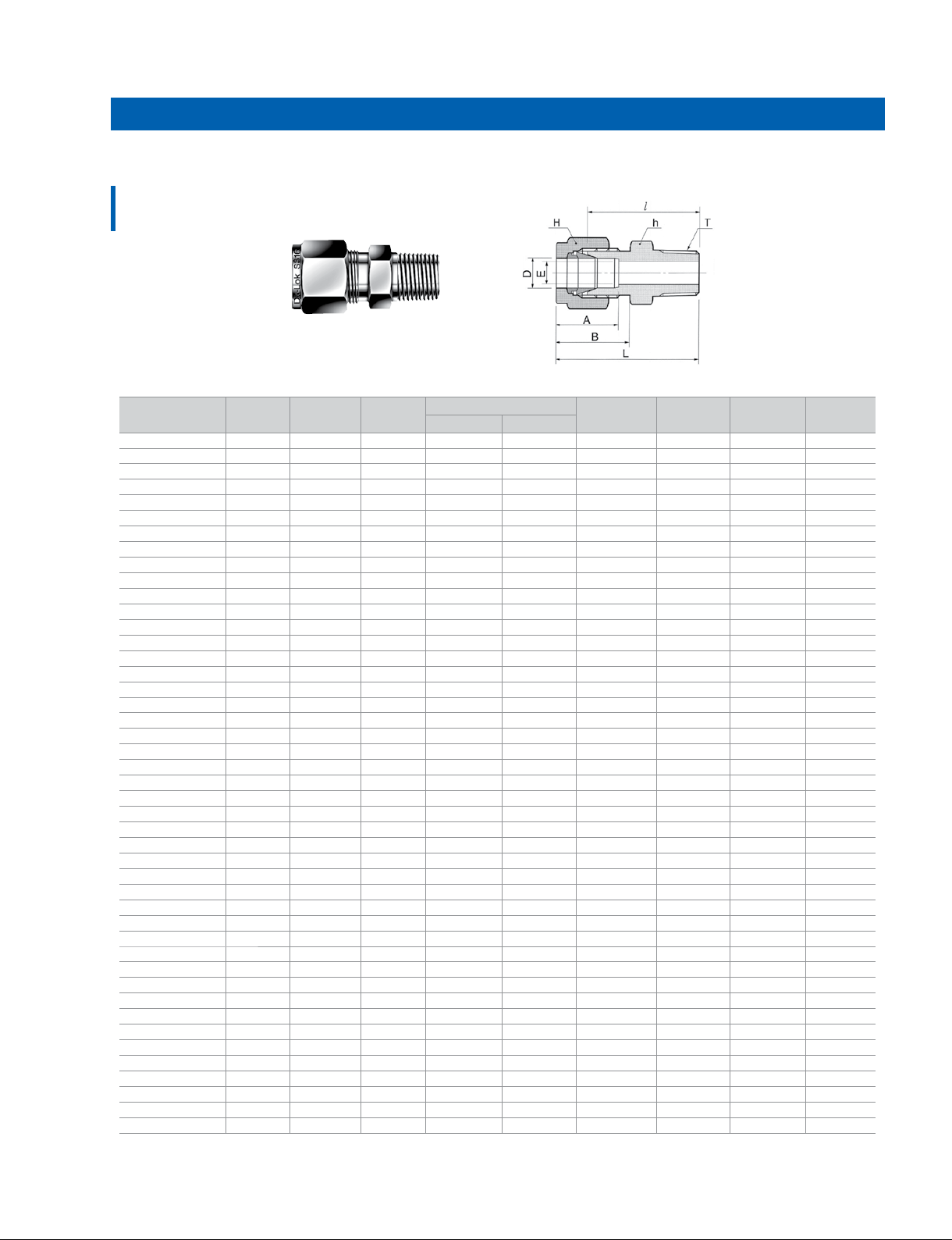
Male Connector
DMC-R
Connects fractional tube to female ISO tapered thread
Tube O.D.
Part No.
DMC2-2R 1/8 3.17 1/8 2.28 7/16 11.11 7/16 11.11 12.70 15.24 23.87 30.48
DMC2-4R 1/8 3.17 1/4 2.28 9/16 14.28 7/16 11.11 12.70 15.24 28.95 35.56
DMC4-2R 1/4 6.35 1/8 4.82 1/2 12.70 9/16 14.28 15.24 17.78 25.40 32.76
DMC4-4R 1/4 6.35 1/4 4.82 9/16 14.28 9/16 14.28 15.24 17.78 30.48 37.84
DMC4-6R 1/4 6.35 3/8 4.82 11/16 17.46 9/16 14.28 15.24 17.78 30.98 38.35
DMC4-8R 1/4 6.35 1/2 4.82 7/8 22.22 9/16 14.28 15.24 17.78 37.33 44.70
DMC5-2R 5/16 7.93 1/8 4.82 9/16 14.28 5/8 15.87 16.25 18.54 26.67 34.03
DMC5-4R 5/16 7.93 1/4 6.35 9/16 14.28 5/8 15.87 16.25 18.54 31.24 38.60
DMC5-16R 5/16 7.93 1 6.35 1-3/8 34.92 5/8 15.87 16.25 18.54 46.2 50.0
DMC6-2R 3/8 9.52 1/8 4.82 5/8 15.87 11/16 17.46 16.76 19.30 27.94 35.30
DMC6-4R 3/8 9.52 1/4 7.11 5/8 15.87 11/16 17.46 16.76 19.30 32.51 39.87
DMC6-6R 3/8 9.52 3/8 7.11 11/16 17.46 11/16 17.46 16.76 19.30 32.51 39.87
DMC6-8R 3/8 9.52 1/2 7.11 7/8 22.22 11/16 17.46 16.76 19.30 38.86 46.22
DMC6-12R 3/8 9.52 3/4 7.11 1-1/16 26.98 11/16 17.46 16.76 19.30 40.38 47.75
DMC8-2R 1/2 12.70 1/8 4.82 13/16 20.64 7/8 22.22 22.86 21.84 28.70 38.86
DMC8-4R 1/2 12.70 1/4 7.11 13/16 20.64 7/8 22.22 22.86 21.84 33.27 43.43
DMC8-6R 1/2 12.70 3/8 9.65 13/16 20.64 7/8 22.22 22.86 21.84 33.27 43.43
DMC8-8R 1/2 12.70 1/2 10.41 7/8 22.22 7/8 22.22 22.86 21.84 38.86 49.02
DMC8-12R 1/2 12.70 3/4 10.41 1-1/16 26.98 7/8 22.22 22.86 21.84 40.38 50.54
DMC8-16R 1/2 12.70 1 10.41 1-3/8 34.92 7/8 22.22 22.86 21.84 46.99 57.15
DMC10-6R 5/8 15.87 3/8 9.65 15/16 23.81 1 25.40 24.38 21.84 34.03 44.19
DMC10-8R 5/8 15.87 1/2 11.93 15/16 23.81 1 25.40 24.38 21.84 38.86 49.02
DMC10-12R 5/8 15.87 3/4 12.70 1-1/16 26.98 1 25.40 24.38 21.84 40.38 50.54
DMC12-8R 3/4 19.05 1/2 11.93 1-1/16 26.98 1-1/8 28.58 24.38 21.84 40.38 50.54
DMC12-12R 3/4 19.05 3/4 15.74 1-1/16 26.98 1-1/8 28.58 24.38 21.84 40.38 50.54
DMC12-16R 3/4 19.05 1 15.74 1-3/8 34.92 1-1/8 28.58 24.38 21.84 46.99 57.15
DMC16-12R 1 25.40 3/4 15.74 1-3/8 34.92 1-1/2 38.10 31.24 26.41 45.21 57.40
DMC16-16R 1 25.40 1 22.35 1-3/8 34.62 1-1/2 38.10 31.24 26.41 50.03 62.23
DMC20-12R 1-1/4 31.75 3/4 15.74 1-3/4 44.45 1-7/8 47.63 41.14 38.86 50.0 72.10
DMC20-16R 1-1/4 31.75
DMC20-20R 1-1/4 31.75 1-1/4 27.68 1-3/4 44.45 1-7/8 47.63 41.14 38.86 55.11 77.21
DMC32-32R 2 50.80 2 45.97 2-3/4 69.85 3 76.20 67.56 62.73 76.20 113.53
D
in. mm in. mm in. mm
T
PTE Min.
1 22.35 1-3/4 44.45 1-7/8 47.63 41.14 38.86 55.11 77.21
Width across at
AB
NJ
LhH
Thermocouple Connector
DMCT
23
Most DK-Lok male connectors can be bored-through thermocouple ttings except
those ttings with small male thread like 1/8 in.
To order, insert T in DMC male connector part number. Example: DMCT8-8N-S
DK-Lok bored-through ttings have no shoulder or sizing angle inside the body. This
allows thermocouples or dip tubes to pass beyond the tting male thread.
Assembly instruction
1. Position the length of thermocouple to pass through tting male thread and hold
it to prevent shifting during assembly.
2. Wrench tightens the nut 1 1/4 turns from nger tight position, keeping the body
steady with backup wrench.
•Tighten the nut 3/4 turn for 1/8, and 3/16; 3, and 4mm Tube Fittings.
All dimensions are in millimeters unless otherwise specied and only for reference subject to change.
DK-Lok Tube Fitting
Male Connector
DMC-R
Connects metric tube to female ISO tapered thread
Part No.
DMC2M-2R 2 1/8 1.7 12 12 12.9 15.3 23.9 30.5
DMC3M-2R 3 1/8 2.4 12 12 12.9 15.3 23.1 29.7
DMC3M-4R 3 1/4 2.4 14 12 12.9 15.3 29.0 35.6
DMC4M-2R 4 1/8 2.4 12 12 13.7 16.1 24.6 31.2
DMC4M-4R 4 1/4 2.4 14 12 13.7 16.1 29.7 36.3
DMC6M-2R 6 1/8 4.8 14 14 15.3 17.7 25.4 32.8
DMC6M-4R 6 1/4 4.8 14 14 15.3 17.7 30.2 37.6
DMC6M-6R 6 3/8 4.8 18 14 15.3 17.7 31.0 38.4
DMC6M-8R 6 1/2 4.8 22 14 15.3 17.7 37.3 44.0
DMC8M-2R 8 1/8 4.8 15 16 16.2 18.6 26.7 34.2
DMC8M-4R 8 1/4 6.4 15 16 16.2 18.6 31.2 38.7
DMC8M-6R 8 3/8 6.4 18 16 16.2 18.6 31.8 39.2
DMC8M-8R 8 1/2 6.4 22 16 16.2 18.6 37.3 44.8
DMC10M-2R 10 1/8 4.8 18 19 17.2 19.5 28.7 36.3
DMC10M-4R 10 1/4 7.1 18 19 17.2 19.5 33.3 40.9
DMC10M-6R 10 3/8 7.9 18 19 17.2 19.5 33.3 40.9
DMC10M-8R 10 1/2 7.9 22 19 17.2 19.5 38.1 45.7
DMC10M-12R 10 3/4 7.9 27 19 17.2 19.5 38.9 46.5
DMC12M-4R 12 1/4 7.1 22 22 22.8 22.0 33.3 43.4
DMC12M-6R 12 3/8 9.5 22 22 22.8 22.0 33.3 43.4
DMC12M-8R 12 1/2 9.5 22 22 22.8 22.0 38.1 48.2
DMC12M-12R 12 3/4 9.5 27 22 22.8 22.0 38.9 49.0
DMC14M-6R 14 3/8 9.5 24 25 24.4 22.0 34.0 44.1
DMC14M-8R 14 1/2 11.1 24 25 24.4 22.0 34.0 44.1
DMC15M-6R 15 3/8 9.5 24 25 24.4 22.0 34.0 44.1
DMC15M-8R 15 1/2 11.9 24 25 24.4 22.0 38.9 49.0
DMC16M-4R 16 1/4 7.1 24 25 24.4 22.0 34.0 44.1
DMC16M-6R 16 3/8 9.5 24 25 24.4 22.0 34.0 44.1
DMC16M-8R 16 1/2 11.9 24 25 24.4 22.0 38.9 49.0
DMC16M-12R 16 3/4 12.7 27 25 24.4 22.0 38.9 49.0
DMC18M-8R 18 1/2 11.9 27 30 24.4 22.0 40.4 50.5
DMC18M-12R 18 3/4 15.1 27 30 24.4 22.0 40.4 50.5
DMC20M-8R 20 1/2 11.9 30 32 26.0 22.0 42.2 52.3
DMC20M-12R 20 3/4 15.9 30 32 26.0 22.0 42.2 52.3
DMC22M-8R 22 1/2 11.9 30 32 26.0 22.0 42.2 52.3
DMC22M-12R 22 3/4 15.9 30 32 26.0 22.0 42.2 52.3
DMC22M-16R 22 1 18.3 35 32 26.0 22.0 47.8 57.9
DMC25M-8R 25 1/2 11.9 35 38 31.3 26.5 45.2 57.5
DMC25M-12R 25 3/4 15.9 35
DMC25M-16R 25 1 21.8 35 38 31.3 26.5 50.0 62.3
DMC28M-16R 28 1 21.8 41 46 36.6 36.6 51.6 72.4
DMC28M-20R 28 1-1/4 21.8 46 46 36.6 36.6 52.3 73.1
DMC30M-20R 30 1-1/4 26.2 46 50 39.6 39.2 55.6 77.2
DMC32M-20R 32 1-1/4 28.6 46 50 42.0 41.6 56.6 79.6
DMC38M-24R 38 1-1/2 33.7 55 60 49.4 47.9 64.0 91.6
Tube O.D.
D
PT
T
E
Min.
Width across at
hH
38 31.3 26.5 45.2 57.5
AB
NJ
L
All dimensions are in millimeters unless otherwise specied and only for reference subject to change.
www.dklok.com
24
 Loading...