

Page 1
DETAIL K2 INC.
CHIPPER ASSEMBLY GUIDE
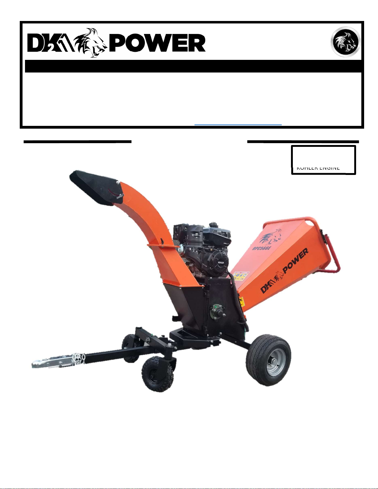
MODEL: OPC566E
6 INCH KINETIC DRUM CHIPPER
DK2 POWER USA
4301 S Valley View Blvd STE 10-11
Las Vegas, NV 89103
1-702-331-5353
PARTS AND SERVICE 702-331-5353 OR WWW.DK2POWER.COM CONTACT US
DETAIL K2, INC.
1080 Clay Avenue Unit 2
Burlington, Ontario, Canada L7L0A1
6IN KINETIC DRUM CHIPPER
DK2 USA EAST
6245 Industrial Parkway
Whitehouse, OH 43571
KINETIC DRUM
DOT TOWABLE
KOHLER ENGINE
OPC566E 6 INCH
KINETIC DRUM CHIPPER
REV 1 – 9-19-2019
Page 2
STEP 1:
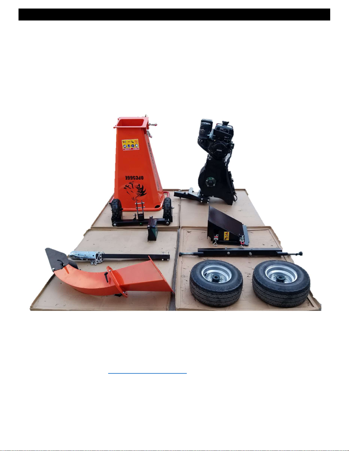
Open and unpack all items. Leave lots of working space.
Inspect all parts.
The CHIPPER is shipped in a crate. Remove all sides before
you begin.
NOTE: UPON INSPECTION OF PARTS IF YOU FIND ANY DAMAGE OR MISSING
PARTS PLEASE CALL DK2 POWER AT 702-331-5353 OR CONTACT US VIA
OUR WEBSITE WWW.DK2POWER.COM
WE WILL REPLACE ANY MISSING PARTS TO YOU FREE
PLEASE DO NOT RETURN TO THE STORE
REV 1 – 9-19-2019
Page 3
STEP 2:
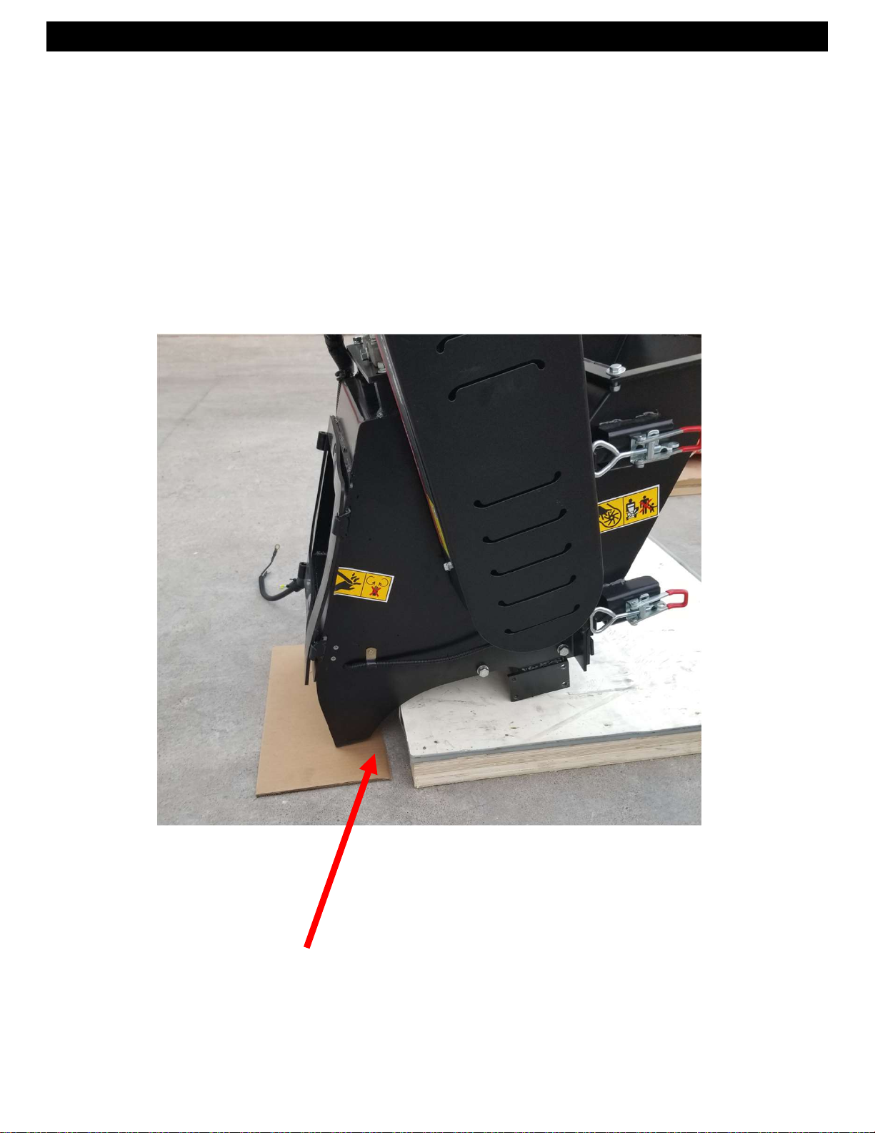
1. PREPARE TO INSTALL THE AXLE
2. Slide chipper body to hang off side of the crate as shown.
3. Have a helper tip the unit forward while you complete the
next step.
Extend the unit off the crate
REV 1 – 9-19-2019
Page 4
STEP 3:
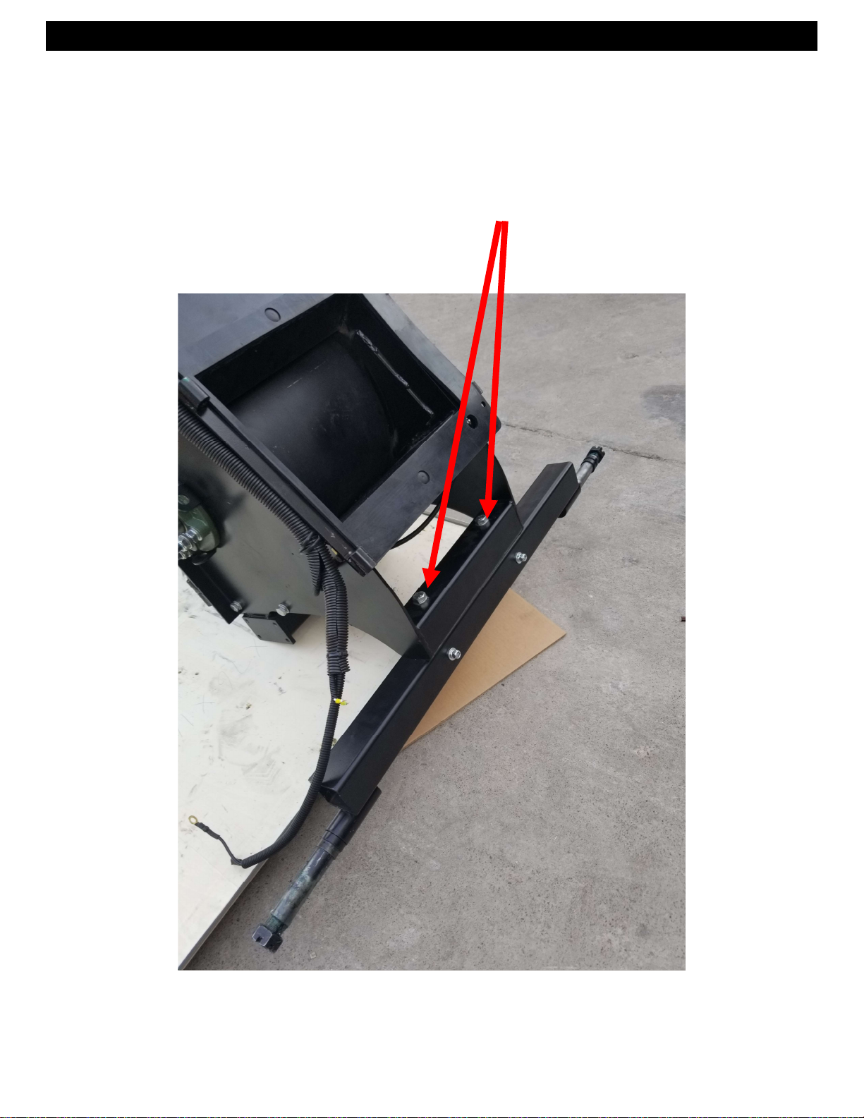
1. Tip the unit forward
2. Install the axle using the 2 bolts and hardware provided and
tighten.
2 BOLTS AND NUTS
REV 1 – 9-19-2019
Page 5
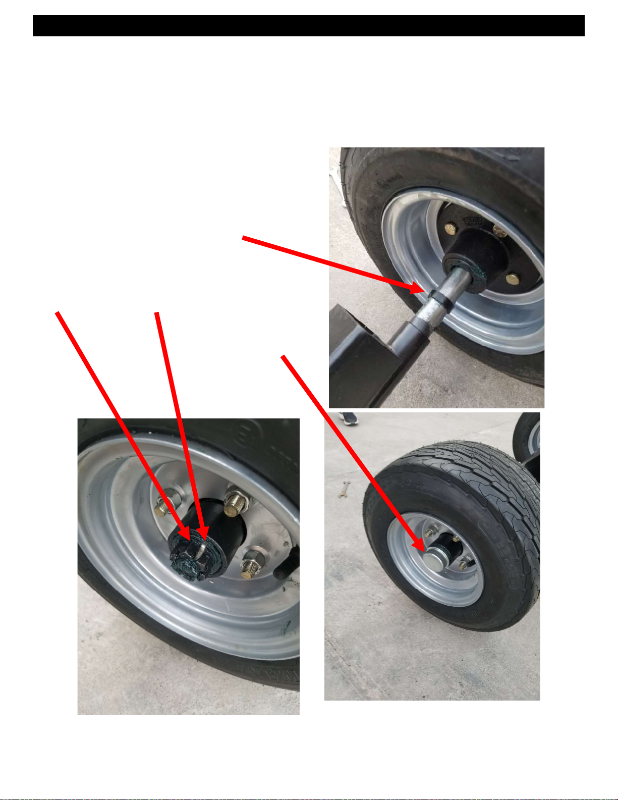
STEP 4:
1. INSTALL THE WHEELS
2. Place 1 black spacer on the axle first
3. Install the wheel, washer, nut and pin.
4. Wheels should spin free.
5. Install end cap
6. Repeat for other wheel.
Spacer
Washer then Nut and Pin
End Cap
REV 2 – 3/6/2020
Page 6
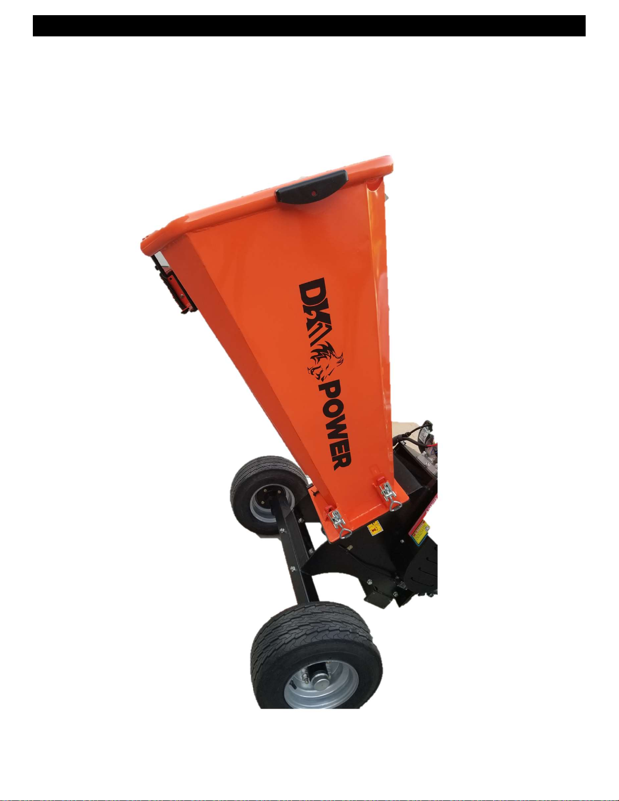
STEP 5:
1. INSTALL FEED CHUTE
2. With a helper slide the feed chute hinge pins into place,
close and latch.
REV 1 – 9-19-2019
Page 7
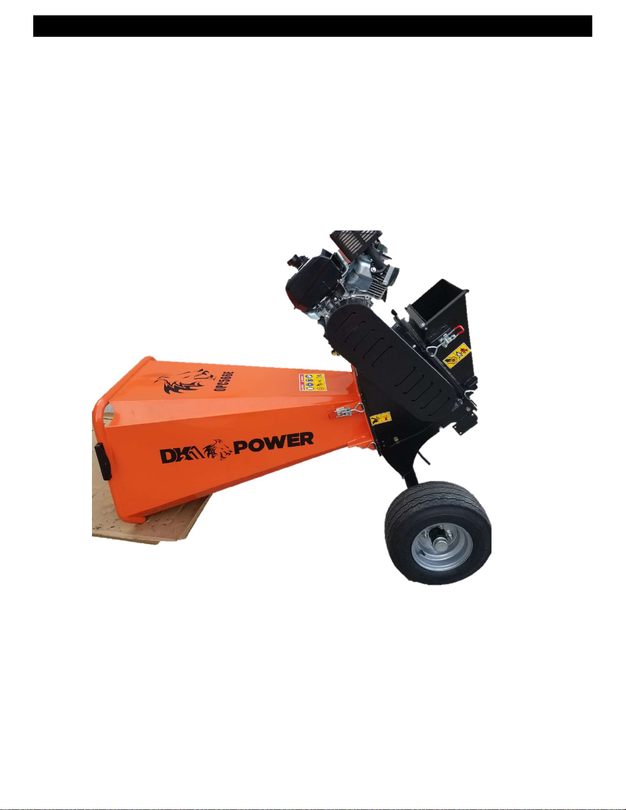
STEP 6
1. Holding the feed chute, lay the unit down as shown
2. Prepare to install the front hitch assembly.
REV 1 – 9-19-2019
Page 8
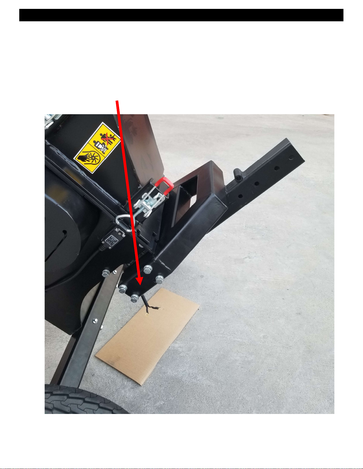
STEP 7
1. Install the front hitch assembly
2. Use 8 bolts and hardware provide and secure tightly
Use bolts provided both sides
REV 1 – 9-19-2019
Page 9
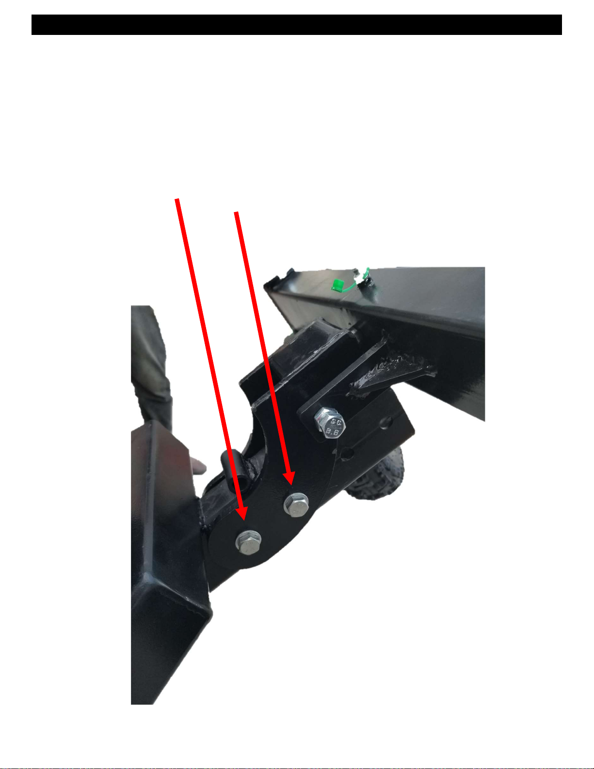
STEP 8
1. Install the articulated front wheel assembly
2. Use bolt and pin hardware provide and semi tight to allow
assembly to raise and lower.
3. Raise and pin when towing
PIN
BOLT
REV 1 – 9-19-2019
Page 10
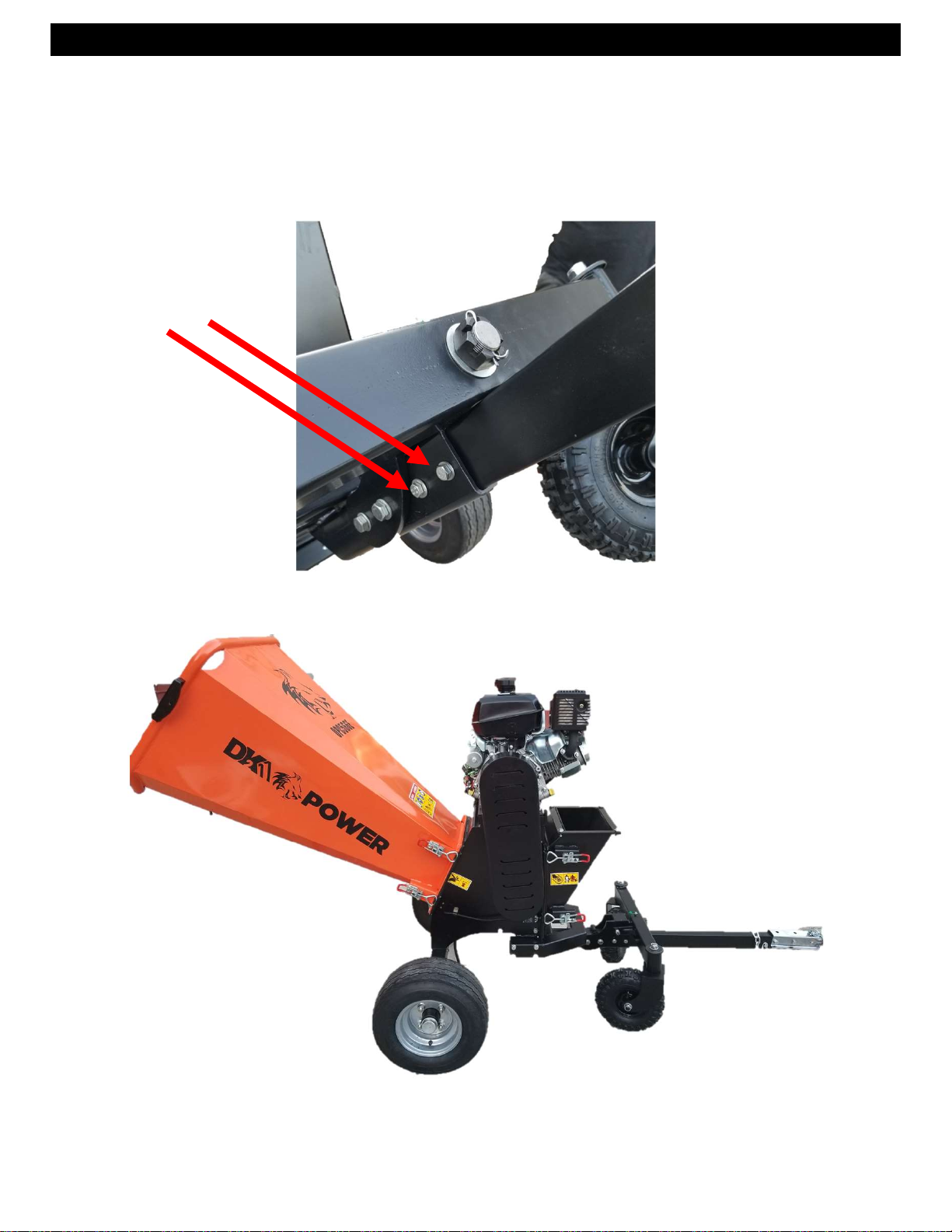
STEP 9
1. Install the TOW BAR
2. Use 2 bolts and hardware provide and secure tightly
3. Tip unit forward and lower to level
Use 2 bolts provided
REV 1 – 9-19-2019
Page 11
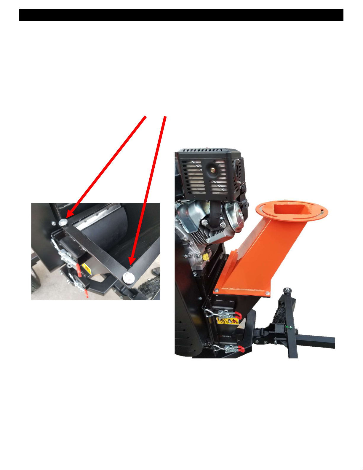
STEP 10
1. Install the Lower Chip Chute
2. Carefully remove the mounting hardware from the frame so
as to NOT drop into the cutting chamber.
3. You can OPEN the door while removing the hardware to be
safe. Then reclose the door to mount the chute.
4. Mount with 4 bolts and hardware provided.
REV 1 – 9-19-2019
Page 12
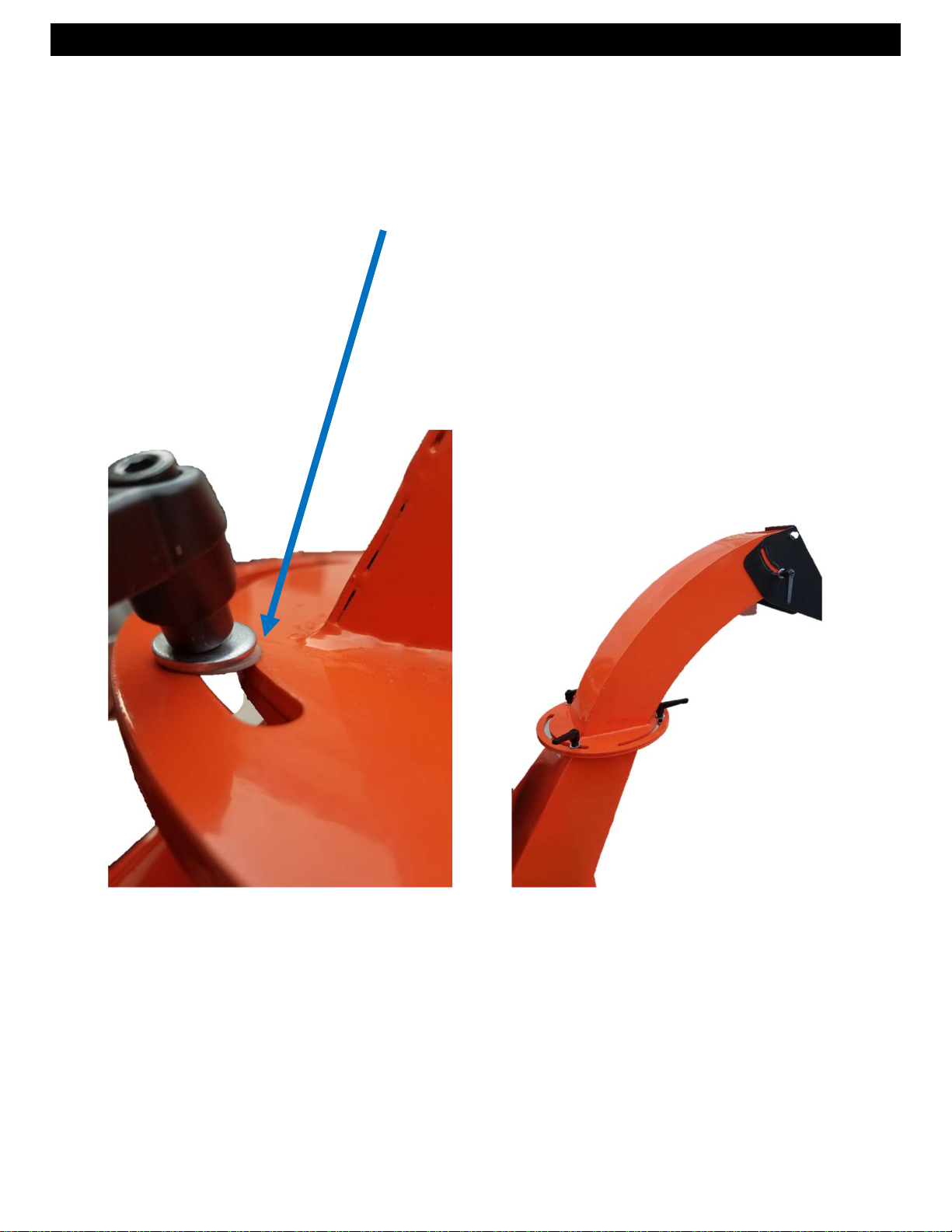
STEP 11
1. INSTALL THE TOP CHIP CHUTE.
2. Use 3 HAND BOLTS and hardware provide and secure tightly
3. PLACE THE NYLON WASHER BETWEEN THE METAL WASHER
AND THE CHUTE AS SHOWN.
REV 1 – 9-19-2019
Page 13
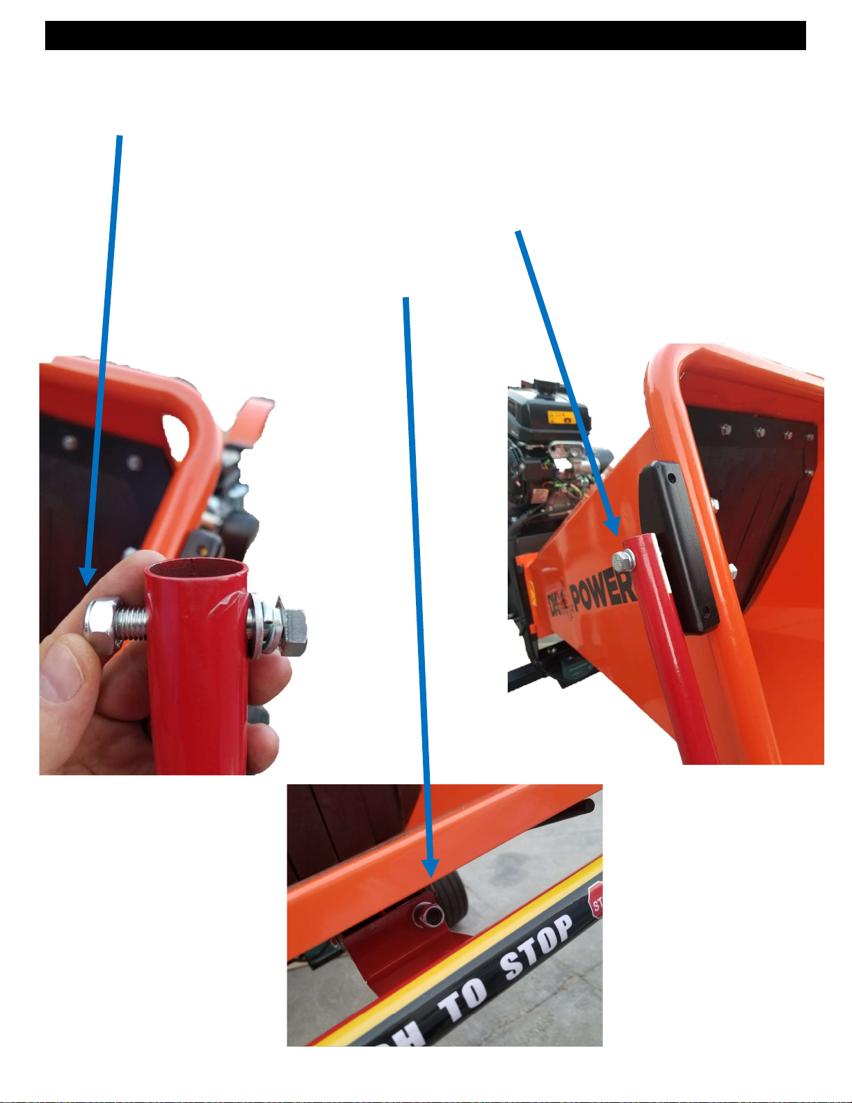
STEP 12
1. Install the Safety shut-off bar
2. REMOVE THE PACKING NUT FROM THE BOLT AND DISCARD.
IT WILL NOT BE NEEDED AND ONLY IS USED TO RETAIN THE
MAIN HARDWARE DURING SHIPPING.
3. Install the 2 bolts and bar as shown.
4. Remove nut from spring bolt,
5. Install bar and replace the nut.
REV 1 – 9-19-2019
Page 14
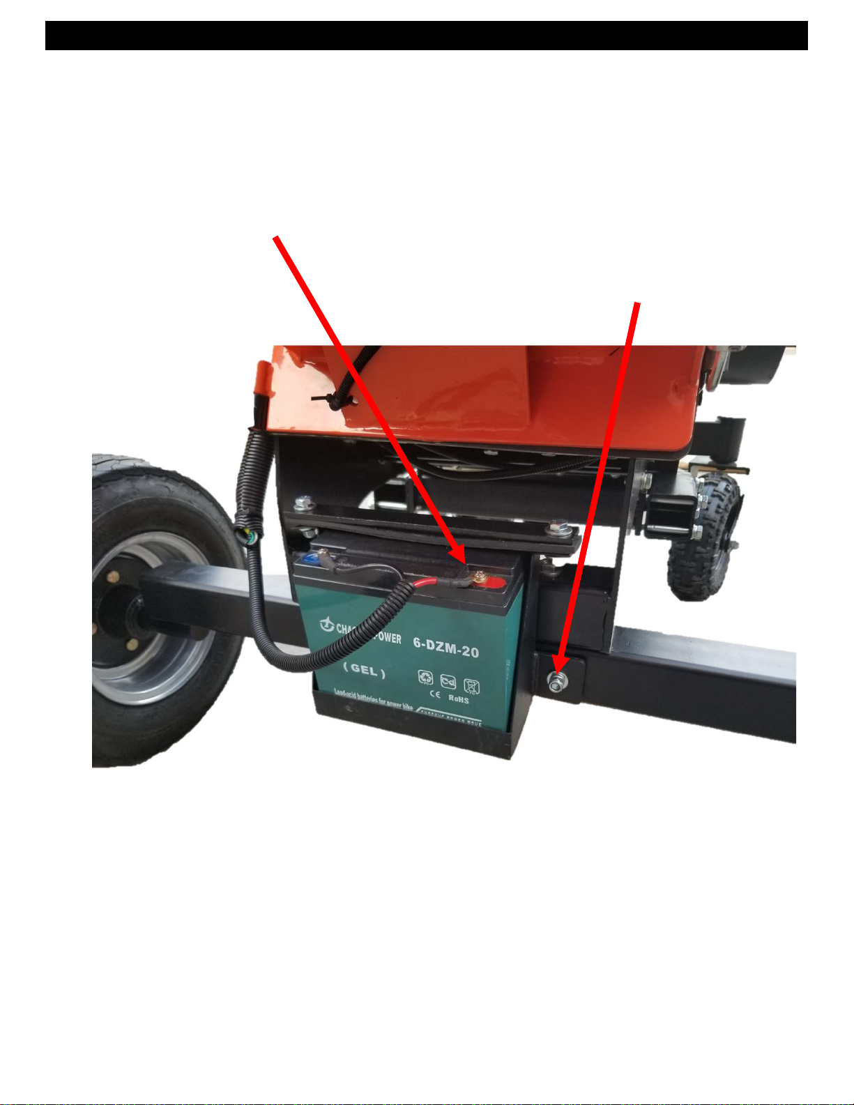
STEP 13
1. Install the Battery
2. Use 2 bolts and hardware provide and secure tightly
3. Connect the wiring as shown.
4. Be carefull as to not touch your wrench to metal frame
when installing the positive red wire.
Use 2 bolts provided
REV 1 – 9-19-2019
Page 15
REV 1 – 9-19-2019
Page 16

Ref.No. Description Ref.No.2 Description3
1
2
3
4
5
6
7
8
9
10
11
12
13
14
15
Rubber fixer strip
Kill switch cover
Return lever spring
Rubber plate
Emergency stop bar
Bar fixture(left)
M10 lock nut
Infeed hopper
Bar fixture(right)
Seal cover(left)
Infeed Damping Rubber
Engine(recoil/electric start)
Engine fixture plate
Main-frame
Spacer Ø35*Ø45*10
34
35
36
37
38
39
40
41
42
43
44
45
46
47
48
Discharge(middle part)
Discharge(top part)
Spacer Ø21*Ø25*95
Fore-wheel fixture
Wheel 4.10-4
Washer Ø16*Ø26*3
Screw M16*12
Dust cap
M24*1.5 slotted nut
Wheel 16*8.0-7
Flange
Rear wheel axle
Bearing F207
Roller
16
17
18
19
20
21
22
23
24
25
26
27
28
29
30
Kill switch
Buckle
Seal cover(right)
Belt inner cover
Discharge Damping Rubber
Arch plate
Front wheel frame
Front wheel rotation frame
M10 screw and nut
M10 lock nut
Axle cover
Bearing 6204
M24*1.5 slot nut
Tow bar
Tow hitch
49
50
51
52
53
54
55
56
57
58
59
60
61
62
63
Blade
Frame-Switch cover
Anvil
Anvil fixture
Battery fixture
Battery box
Battery 12V20AH
Bearing cover
M10 nut
SpringØ20*Ø16*Ø2.0*135
Restore pole
Screw bolt
V-Belt 17*1143
Engine pulley
Roller Pulley
31
32
33
Chain
Deflector
Discharge(bottom part)
64
65
66
Belt cover
Fore-wheel fixing frame
REV 1 – 9-19-2019
Page 17
READ THE KOHLER ENGINE MANUAL SUPPLIED WITH YOUR
UNIT FOR FULL ENGINE OPERATION, SAFETY, AND
MAINTENANCE.
YOUR UNIT HAS A COMMERCIAL KOHLER ENGINE WITH A 3YR
PARTS AND SERVICE WARRANTY. FOR WARRANTY IN YOUR
AREA CONTACT THE NEAREST KOHLER DEALER.
VISIT WWW.KOHLERENGINES.COM FOR PARTS, SERVICE,
MANUALS, AND DEALER LOCATIONS.
REV 1 – 9-19-2019
Page 18

OPERATION – BEFORE STARTING ENGINE
CLEAR AREA OF ALL PEOPLE AND PROPERTY THAT COULD BE DAMAGED.
THINK SAFETY. THIS CHIPPER CAN CAUSE INJURY IF SAFETY IS NOT
ENFORCED. ONLY ONE OPERATOR SHOULD WORK THIS UNIT. NEVER HAVE
ANOTHER PERSON IN THE AREA OR IN FRONT OF THE CHIP EXIT CHUTE.
IF YOUR UNIT WILL NOT START –
1. CHECK THE OIL LEVEL. YOUR ENGINE HAS A LOW OIL SHUTOFF PROTECTION
AND WILL NOT START IF LOW ON OIL.
2. MAKE SURE SPARK PLUG WIRE IS SEATED.
3. MOVE THE GAS LEVER ON TO THE RIGHT. LEFT POSITION IS OFF.
4. USE THE CHOKE IF NEED TO START IN COLD WEATHER.
5. CHECK YOUR GAS LEVEL
• DO NOT WEAR LOOSE FITTING CLOTHES THAT COULD GET STUCK IN THE RAM
• ONLY CHIP WOOD, NO METAL OR PLASTIC OR RUBBER. WOOD ONLY.
• CHILDREN SHOULD NOT RUN THIS EQUIPMENT
• STAY ALERT OF YOUR SURROUNDING AND PERSONS THAT COULD APEAR IN THE
AREA WHILE YOU ARE WORKING.
• LOAD TREES INTO FEED CHUTE. THIS IS A GRAVITY DRUM FEED CHIPPER. MOST
TREES UPTO 3 IN DIAMETER MAY FEED ON THEIR OWN HOWEVER LARGER DIA
TREES SHOULD BE CONTROLED INTO THE CHIPPER. ALLOW TIME BETWEEN CUTS
ON LARGER TREES FOR DRUM TO REGAIN RPM BEFORE THE NEXT CUT.
• IF ENGINE SPEED IS REDUCED WHEN CHIPPING ADJUST ROLLER SPEED.
• WEAR SAFETY GLASSES, GLOVES AND PROTECTIVE SHOES.
• OPERATE OUTDOORS ONLY – GAS FUMES ARE DEADLY INDOORS.
RUN ENGINE AT FULL RPM.
ALLOW MACHINE TO REGAIN RPM BETWEEN CHIPPING.
NEVER DISCONNECT SAFETY SWITCHES OR RUN WITH COVERS OPEN
RESPECT THE MACHINE- IT IS POWERFUL – BE SAFE IN YOUR OPERATION
TOW MACHINE SAFELY 25MPH MAX ON STREETS WITH D.O.T. APPROVED TIRES.
LIFT THE FRONT ARTICULATED WHEELS AND PIN WHILE TOWING.
REV 1 – 9-19-2019
Page 19

PLEASE DO NOT RETURN TO THE STORE
YOU HAVE A 1 YEAR WARRANTY AND DK2 WILL REPLACE A DEFECTIVE PART FOR FREE
CALL US AT
WHAT IS COVERED
DK2 Inc. warrants to the original purchaser of any DK2 product that it will be free and clear of manufacturing
defects in workmanship and materials under normal use and service for a period of one (1) year from the
date of the original purchase.
If within one (1) year from the original date of purchase this product fails due to defect in material or
workmanship. DK2 POWER outdoor power equipment is 1-year parts only warranty no labor.
Upon expiry of one (1) year, Detail K2 will have no further liability related to the product. Detail K2 does not
authorize any party, including its authorized distributors or dealers, to offer any other warranty on behalf of
Detail K2 Inc.
KOHLER ENGINES – KOHLER CH SERIES ENGINES COMMERCIAL 3 YR PARTS AND LABOR WARRANTY
see your Kohler manual for specific warranty.
DIESEL TRACTORS – Chassis component parts only, no labor, ENGINES – 1 YR KOHLER WARRANTY
DK2 POWER OUTDOOR EQUIPMENT – 1-Year parts only, no labor.
THIS WARRANTY DOES NOT COVER OR APPLY TO:
Damage to the product due to misuse, mishandling and abuse
(b) Improper installation, maintenance and storage
(c) Expendable parts such as nuts and bolts, pins and springs, wiring and switch components, hydraulic
hoses and fittings, cutting teeth, cutting chains, cutting blades, throttles, belts and tires.
(d) Normal wear and tear
(e) Consequential damage & incidental damages such as damage to persons or property
702-331-5353
FOR FAST WARRANTY PARTS AND QUESTIONS
PROCEDURE FOR OBTAINING AN RETURN AUTHORIZATION
Within the one (1) year warranty period, the purchaser of the product must notify DK2 of the claimed defect
and provide proof of original purchase. At this time the validity of the claim will be determined, and if
approved replacement parts will be issued.
No returned product will be accepted under warranty unless accompanied by an RGA# issued by Detail K2
Inc.
RESOLUTION FOR A DEFECTIVE PRODUCT
DK2 POWER – Tractors, Chippers, Stump Grinders, Log Splitters, and Outdoor Power Equipment.
Call DK2 at 702-331-5353 in Las Vegas between 8am-4pm M-F Pacific Time.
REV 1 – 9-19-2019
 Loading...