


Professional USB Turntable
USER MANUAL (ENGLISH)---------------------------------------------------------------------P1-P9
CONTENTS:
MANUEL D’UTILISATION (FRANÇAIS)--------------------------------------------------P10-P18
CONTENUS:
Schnellbednugscanleitung (DEUTSCH) -----------------------------------------------P19-P27
INHALT:
Snel Begin Het Handboek van de eigneaar (DUTCH) ------------------------------P28-P36
INHOUD
Manual de incio rápido del usuarío (ESP AÑOL) ---------------------- ---------------P37-P45
CONTENIDO
Manual Rapido di Utilizzazione (ITALIANO)
In Process
IMPORTANT SAFETY INSTRUCTIONS
OPERATION
CONTROLS OVERVIEW
SPECIFICATIONS
INFORMATION DE SÉCURITÉ IMPORTANTE
AVANT L’UTILISATION
VUE D’ENSEMBLE DES COMMANDES
CARACTERISTIQUES
WICHTIGE SICHERHEITSHINWEISE
BEDIENUNG
STEUERUNG UND FUNKTIONEN
EIGENSCHAFTEN
BELANGRIJKE VEILIGHEIDSVOORZORGEN
DE BEDIENING
OVERZICHT V AN DE BEDIENINGSKNOPPEN
TECHNISCHE GEGEVENS
IMPORTANTES INSTRUCCIONES DE SEGURIDAD
OPERACIONES
VIST A DE CONJUNTO DE LOS CONTROLES
ESPECIFICACIONES

IMPORTANT SAFETY INSTRUCTIONS
1. Read Instructions – All the safety and operating instructions should be read before this product is operated.
2. Retain Instructions - The safety and operating ins tructions should be retained for future reference.
3. Heed Warnings - All warnings on the appliance and in the operating instructions should be adhered to.
4. Follow Instructions - All operating and use instructions should be followed.
5. Water and Moisture - The appliance should not be used near water - for example, near a bathtub, washbowl, kitchen
sink, laundry tub, in a wet basement, or near a swimming pool, and the like.
6. Carts and Stands - The appliance should be used only with a cart or stand that is recommended by the
manufacturer. An appliance and cart combination should be moved with care. Quick stops, excessive
force, and uneven surfaces may cause the appliance and cart combination to overturn.
7. Wall or Ceiling Mounting - The product should not be mounted to a wall or ceiling.
8. Heat - The a ppli ance shou ld be situ ated away from heat sources such as radiators, heat registers, st oves , o r oth er
appliances (including amplifiers) that produce heat.
9. Power Sources – This product should be operated only from the type of power source indicated on the rating label. If you
are not sure of the type of power supply to your home, consult your product dealer or local power company. For
products intended to operate from battery power, or other sources, refer the operating instructions.
10. Grounding or Polarization – This product may be equipped with a polarized alternation-current line plug (a plug having
one blade wider than the other). This plug will fit into the power outle t only one way. This is a safety feature. If you are
unable to insert the plug fully into the outlet, try reversing the plug. If the plug should still fail to fit, contact your
electrician to replace your obsolete outlet. Do not defeat the safety purpose of the polarized plug.
11. Power-Cord Protection-Power-supply cords should be routed so that they are not likely to be walked on or pinched by
items placed upon or against them, paying particular attention to the cord in correspondence of plugs, convenience
receptacles, and the point where they exit from the appliance.
12. Cleaning - The appliance should be cleaned only as recommended by the manufacturer. Clean by wiping with a cloth
slightly damp with water. Avoid getting water inside the appliance.
13. For AC line powered units - Before returning repaired unit to user, use an ohm-meter to measure from both AC plug
blades to all exposed metallic parts. The resistance should be more than 100,000 ohms.
14. Non-use Periods-The power cord of the appliance should be unplugged from the outlet when left unused for a long
period of time.
15. Object and Liquid Entry-Care should be taken so that objects do not fall and liquids are not spilled into the enclosure
through openings.
16. Damage Requiring Service-The appliance should be serviced by qualified service personnel when:
A. The power-supply cord or the plug has been damaged; or
B. Objects have fallen, or liquid has been spilled into the appliance; or
C. The appliance has been exposed to rain; or
D. The appliance does not appear to operate normally or exhibits a marked change in performance; or
E. The appliance has been dropped, or the enclosure damaged.
17. Servicing-The user should not attempt any service to the appliance beyond that described in the operating
instructions. All other servicing sho uld b e referred to qualified service personnel.
18. Ventilation – Slots and openings in the cabinet are provided for ventilation and to ensure reliable operation of the
pro duct and t o pr otec t it f rom overheating, and these openings must not be blocked or c over ed. T he op enin gs sh ould
never be blocked by placing the product on a bed, sofa, rug, or other similar surface. T his product should not be place d
in a built-in installation such as a bookcas e or rack unless proper ventilation is the manufacturer’s instructions have
been adhered to.
19. Attachments – do not use attachments not recommended by the product manufacturer as they may cause hazards.
20. Accessories – Do not place this product on an unstable cart, stand, tripod, bracket, or table. The product may fall,
causing serious injury to a child or adult, and serious damage to the product. Use only with a cart, st and, tripod, bracket,
or table recommended by the manufacturer, or sold with the product. Any mounting of the product should follow the
manufacturer’s instructions, and should use a mounting accessory recommended by the manufacturer.
21. Lightning – For added protection for this product during a lightning storm, or when it is left unattended and unused for
long periods of time, unplug it from the wall outlet and disconnect the antenna or cable system. This will prevent
damage to the product due to lightning and power-line surges.
22. Replacement Parts – When replacement parts are required, be sure the service technician has used replacement
parts specified by the manufacturer or have the same characteristics as the original part. Unauthorized substitutions
may result in fire, electric shock, or other hazards.
23. Safety Check – Upon completion of any service or repairs to this product, ask the service technician to perform safety
checks to determine that the product is in proper operating condition
1
CAUTION: To reduce the risk of electric shock, do not remove any cover.
No user-serviceable parts inside. Refer servicing to qualified service
personnel only.
The lightning flash with arrowhead symbol within the equilateral triangle is intended to alert the use to the
presence of un-insulated “dangerous voltage” within the product’s enclosure that may be of sufficient
magnitude to constitute a risk of electric shock.
The exclamation point within the equilateral triangle is intended to alert the user to the presence of important
operation and maintenance (servicing) instructions in the literature accompanying this appliance.
CAUTION
To prevent electric shock, do not use this polarized plug with an extension cord, receptacle or other outlet unless the
blades can be fully inserted to prevent blade exposure.
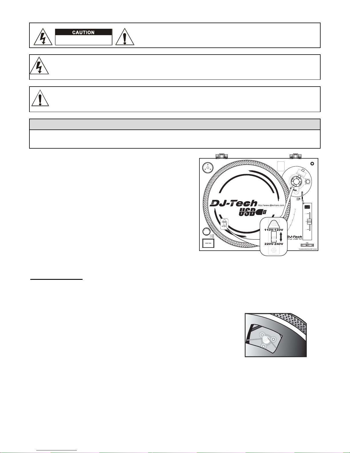
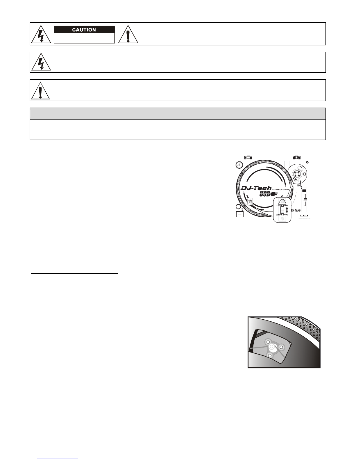
LINE VOLTAGE SELECTION
Just for dual voltage mode only! Because power supplies vary from
location to location we have incorporated a selectable power supply.
The desired voltage may be set with the VOLTAGE SELECTOR
switch located under the platter. (use a flat head screw driver).
Do not force the VOLTAGE SELECTOR switch as this may cause
damage.
If the VOLTAG E SELECTOR switch does not move smoothly, please
contact a qualified service technician.
BEFORE USE
Check for the following parts included in the package with the main unit:
Platter
Slipmat
Headshell
Cartridge
USB cable
Counter weight
DISC
RCA cable
Dust cover
45 rpm adaptor
Instruction manual
Very Important!
Do not forget to attach rubber belt to motor for correct operation. After placing the
Turntable Platter onto the turntable through the Center Spindle, move one of the
large windows on the Platter to top right corner. Attach rubber belt around motor.
(Rubber belt is already attached to the underside of the Turntable Platter.)
Notes:
1. Do not connect the AC power plug before assembly has been completed.
2. Before turning the power on, make sure once again all the connections and power voltage settings are correct.
Always turn off the power when connecting or disconnecting.
3. Read this manual carefully before using the unit .Be sure to store the manual in a safe place for future reference.
DO NOT OPEN
RISK OF ELECTRIC SHOCK
2

ASSEMBLY
1. Remove the main unit with the packing from the box and remove the packing.
2. Set the 45-rpm adaptor on the main unit.
3. Set the turntable platter onto the center spindle.
4. Set the slip mat on the platter.
5. Installation of cartridge:
When installing a cartridge, refer to the operating instructions of that cartridge.
During installation, attach the stylus protector to guard the stylus tip from damage.
(a) Connect the lead wires to the cartridge terminals. The terminals of most cartridges are color-coded. Connect each
lead wire to the terminal of the same color.
White (L+)…………………………… Left channel+
Blue (L-) .....................………………Left channel-
Red (R+) ......................…………… Right channel+
Green(R-) ................………………. Right channel-
(b) Install the cartridge to the headshell and tighten it with screws provided with the cartridge.
6. Insert the headshell into the front end of the tonearm, and then turn the lock nut counterclockwise with the headshell
firmly held horizontally.
7. Slide counterweight onto tonearm. Twist it lightly and it will screw onto the rear shaft of the tonearm.
8. Adjustment of horizontal “zero” balance and stylus pressure:
(a) Remove the stylus protector from the headshell; do not touch the stylus tip during the adjustment.
(b) Set the cueing lever to the lowered position.
(c) Release the tonearm clamp and lift the tonearm from the armrest to free it.
(d) Rotate the counterweight until the tonearm is approximately balanced horizontally (floats freely).
(e) Refasten the tonearm with the tonearm clamp.
(f) Hold the counterweight stationary with one hand and rotate only the stylus-pressure ring to bring the number "0" of
the ring into alignment with the centerline on the tonearm rear shaft.
(g) Rotate the counterweight including the stylus-pressure ring counterclockwise until the scale shows the value
corresponding to the pressure of the stylus used. Should you use a separate Stylus, please follow the
manufacturer’s instructions.
9. Set the anti-skating control knob to the same value as the stylus pressure.
10. Install the dust cover to the main unit’s dust cover hinges.
PLACEMENT
Do not place the unit in a location where it will be exposed to direct sunlight or near a heating appliance.
Do not place the unit in a location where there is high humidity or a lot of dust.
Cartridge may pick up slight sound pressures or vibrations of the speakers coming along the floor or through the air
resulting in feedback or “howling” sound. Find a location that is very stable and vibration free.
The legs have functions for adjusting the height of the unit itself. Adjust the legs to stabilize the main body horizontally.
3
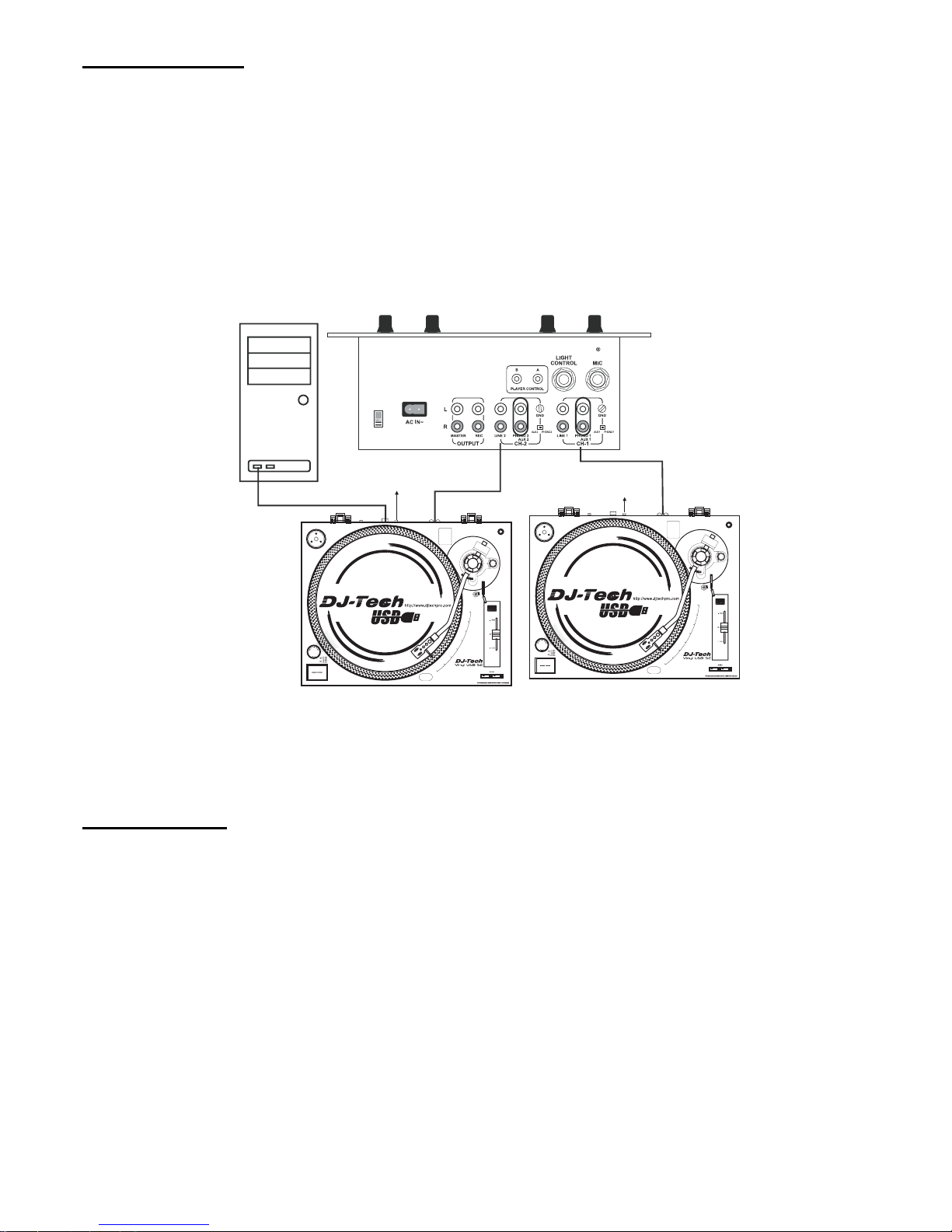
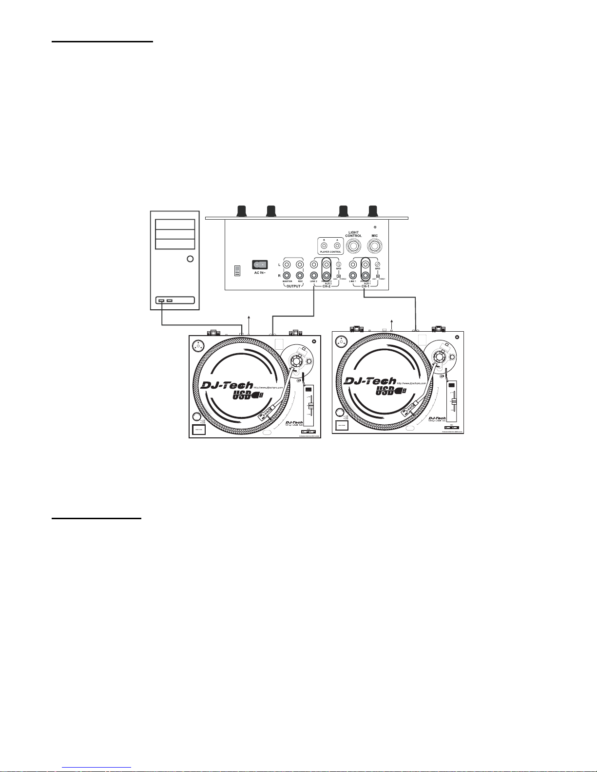
CONNECTIONS
Before connecting the unit it is advised that you also consult your current equipment instruction manual.
IMPORTANT : Be sure to turn off the equipment before you make changes to the different connections.
1. Connect the power cord to an AC outlet.
2. Connect the RCA cable to the PHONO input of your AMPLIFIER.
Output terminals Amplifier (Receiver)
L (White) L Channel
R (Red) R Channel
NOTE:
If this connection is not made or is loose, a power source "HUM" will result.
You can also use a line input by setting the phono / line switch at the rea r of the turntable to line.
3. Connect PC via USB cord.
OPERATIONS
1. Turn the On/Off Switch clockwise to turn on the power, the speed indicator and the strobe-illuminator, which is located
beneath the On/Off switch, will light up.
2. Place a record on the slip mat. When playing a 45-rpm record with a large center hole, place the 45-rpm adapter on the
center spindle.
3. Set the speed to match the record.
4. Remove the stylus protector from the Headshell Stylus and then release the Tonearm clamp.
5. Set the cueing lever to the up position.
6. Press the Start/Stop Button; the turntable platter will start to rotate.
7. Move the tonearm over the desired groove.
8. Set the cueing lever to the down position, the tonearm will descend slowly onto the record and begin playing.
9. When play is finished, raise the cueing lever, move th e tonearm onto the Tonearm clamp.
10. Press the Start/Stop Button to stop the platter from rotating. Turn the On/Off Switch counterclockwise to turn off the
power.
*SUSPEND PLAY
Set the cueing lever to “UP” position during play, the stylus tip of the cartridge will be lifted from the record.
PC
Set thePHONO/LINE
swi tch to “LI NE” .
Set thePHONO/LINE
switch to“PHONO” .
4

CHANGING THE SPEED
As long as the pitch control is in center “detent” click position, the turntable is operated at selected speed.
The speed can be increased or decreased by 10% by the pitch control.
An incorrect adjustment done on purpose can also be used to have the turntable rotate extremely slow or fast.
The strobe dots at the edge of the turntable are used for speed monitoring.
MAINTENANCE
Clean the stylus periodically with a soft brush to prevent the accumulation of dust.
When sound becomes distorted or noisy, check the stylus. If the stylus is worn out, replace it with a new one.
From time to time, the dust cover and turntable cabinet should be wiped down with a soft, rdy cloth.
Volatile materials should not be used, such as: alcohol, thinner, benzine etc. They may remove the paint or damage the
luster.
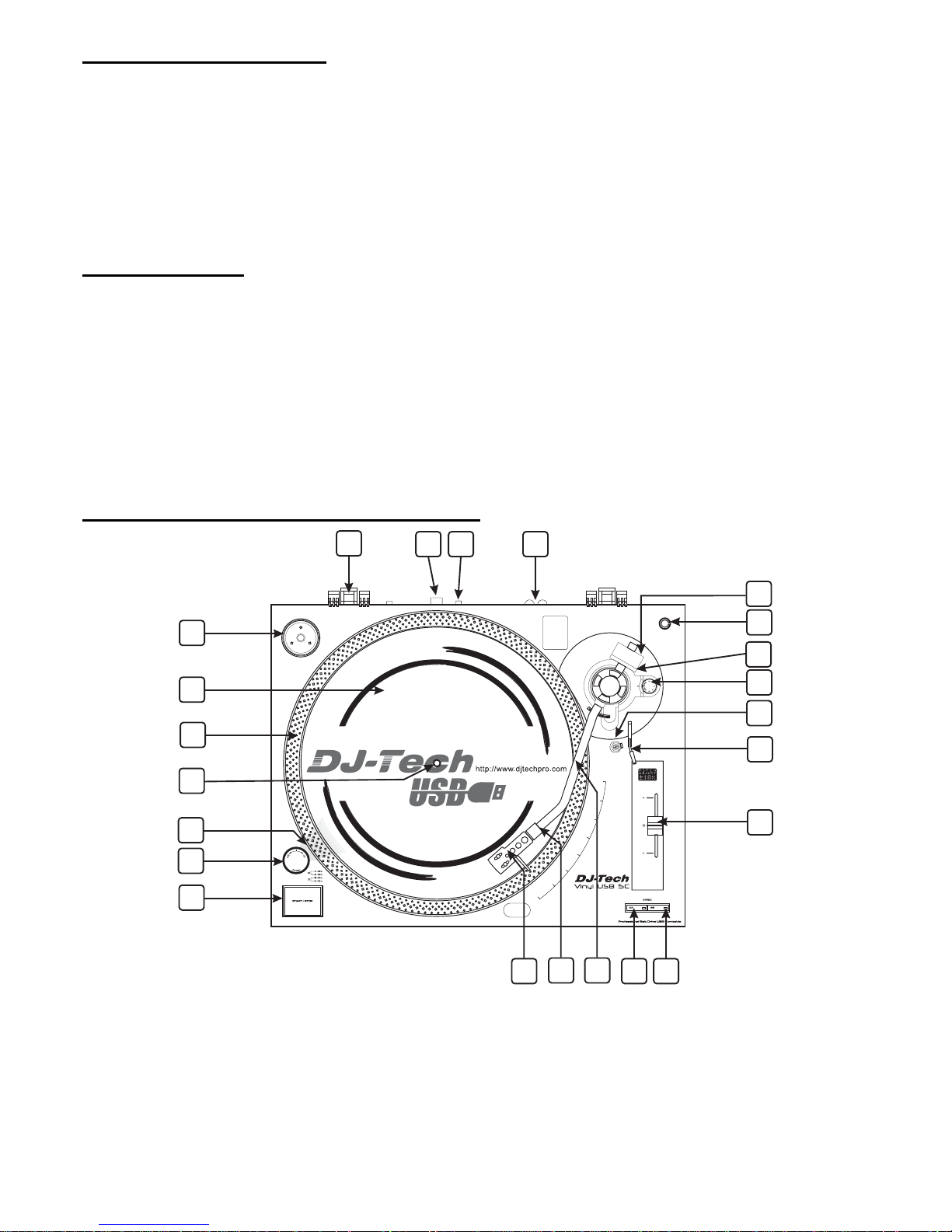
CONTROLS OVERVIEW
1. 45-rpm Adaptor
This adapter allows you to play standard 7” EP vinyl
records with large center holes. Place the adapter on
the CENTER SPINDLE 7" records.
2. Turntable Platter
This platter connects directly to the center spindle. The
platter and center spindle holds a vinyl record perfectl y
center. The platter also spins the record at a consistent
speed.
3. Strobe Indicators
The PLATTER has four rows of indicators. These
indicators are used to visually detail various stages of
pitch. The indicators are illuminated by the STROBE
INDICATOR PILOT LAMP. Each row may appear to
stand still at different pitch levels.
Note: The use of heavy fluorescent lighting directly
above the turntable will defeat the STROBE LAMP
PILOT LAMP affect indicator accuracy.
1
3
4
6
5
7
13
14
15
16
17
18
9
8
11
12
10
23
21
22
19
2
20
5

4. Center Spindle
This spindle holds the turntable PLATTER records
stable and centered.
5. Strobe Indicators Pilot Lamp
This is lamp specially designed to pulse a beam of light
at the STROBE INDICATORS on the turntable PLATTER.
This will give the illusion that indicators are n o t spinni n g
at certain speeds.
6. Power Switch
This is a rotary power switch. To turn main power on
turn the switch in a clockwise direction. To turn main
power off turn the switch in counterclockwise direction.
7. Start/Stop Button
This over sized push button cont rols platter moti on. When
the unit is turned on the platter will not automatically
begin to spin. Pressing the button once will engage the
high torque motor and spin the platter, pressing this
again will stop the platter.
8. Headshell
The included HEADSHELL is used to connect your stylus
with the tone arm.
9. Headshell Locking Nut
After attaching the headshell to the tonearm, this
locking nut will securely hold the headshell to the
tonearm.
10. S-Shaped Tone Arm
The tonearm is the mechanism that holds the HEADSHELL and stylus allowing it to glide across a re cord.
11. 33-RPM Speed Select Button
Engaging this button will rotate the platter at 33
revolutions per a minute (RPMs). A function LED will
glow when this function is activated.
12. 45- RPM Speed Select Button
Engaging this button will rotate the platter at 45 RPMs.
A function LED will glow when this function is activated.
13. Pitch Control Slider
This slider is used to adjust the playback pitch
percentage (platter speed).
14. Tone Arm Lever
This lever is used to safely elevates the tone arm
above a record surface without endangering a records
surface.
15. Arm Rest Clamp and Rest
Use this rest to safely hold the tonearm in position
during non-use and transportation.
16. Anti-skate Knob
The anti-skate applies inward force to the tonearm to
prevent outward skipping across the record due to the
centrifugal force cause by platter rotation. The anti-skate
value should be equally to that of the stylus
counterweight pressure.
17. Stylus-Pressure Ring
* The counterweight scale must face toward the DJ.
18. Extra Stylus Holder
This cut out has been designed to safely store an extra
stylus headshell.
19. Counterweight
Use the counterweight to balance the tone arm and t o
adjust the stylus pressure.
20. Hinge For Dust Cover
21. USB Socket (USB cable limit within 3m)
After connecting the Turntable to the computer via USB,
you can record your vinyl to your hard disk using the
included Audacity software.
22. Phono/Line Selector
This switch is used to change the mode of phono
output or line output.
23. RCA output Jacks
The output is able to switch to PHONO output or LINE
output. For example: These jacks are used to send a
low voltage "phono" level output signal to a mixers
"phono" input jacks. Turntables should be connected to
“Phono” inputs on a mixer. The red colored RCA jack
repr e s e n t s t h e r i g h t ch a n nel input and the white
represents the left channel input.
6
AUDACITY SOFTWARE OVERVIEW
Audacity is free software, licensed under the GNU General Publi c License (GPL). More informat ion as well a s open sou rce
code can be found on the CD included or on the web at http://audacity.sourceforge.net/
* Please ensure you have installed the software before starting.
Setting up your PC to work with Audacity
1. Connect an input source to the unit.
2. Connect the USB lead to your computer.
3. Install the Audacity recording software.
4. Open the Audacity program.
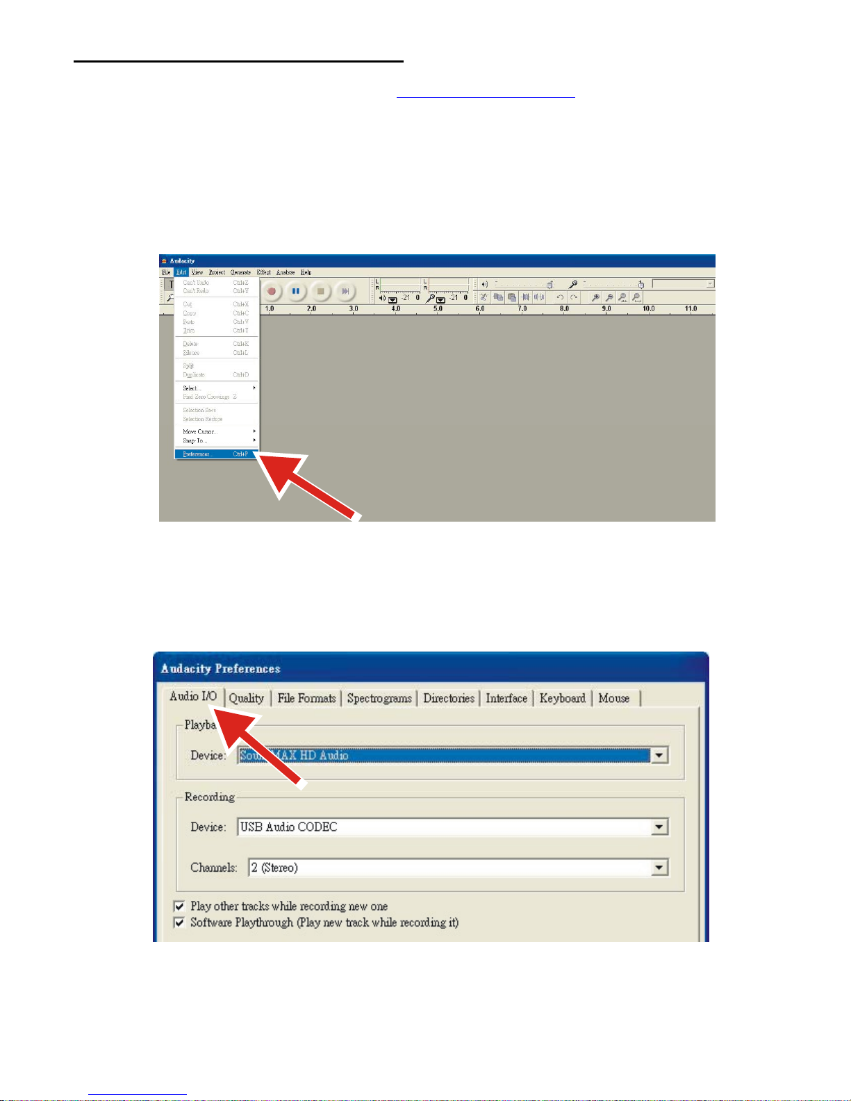
5. Select Preference from the Edit tab in the Audacity Menu.
6. Select Audio I/O tab at the top left.
Under Playback, Device, select your internal sound card.
Under Recording, Device, select USB Audio CODEC.
Under Recording, Channels, select 2 (Stereo).
Check the box marked Play other tracks while recording new one.
Check the box marked Software Playthrough.
7
Recording Albums with Audacity
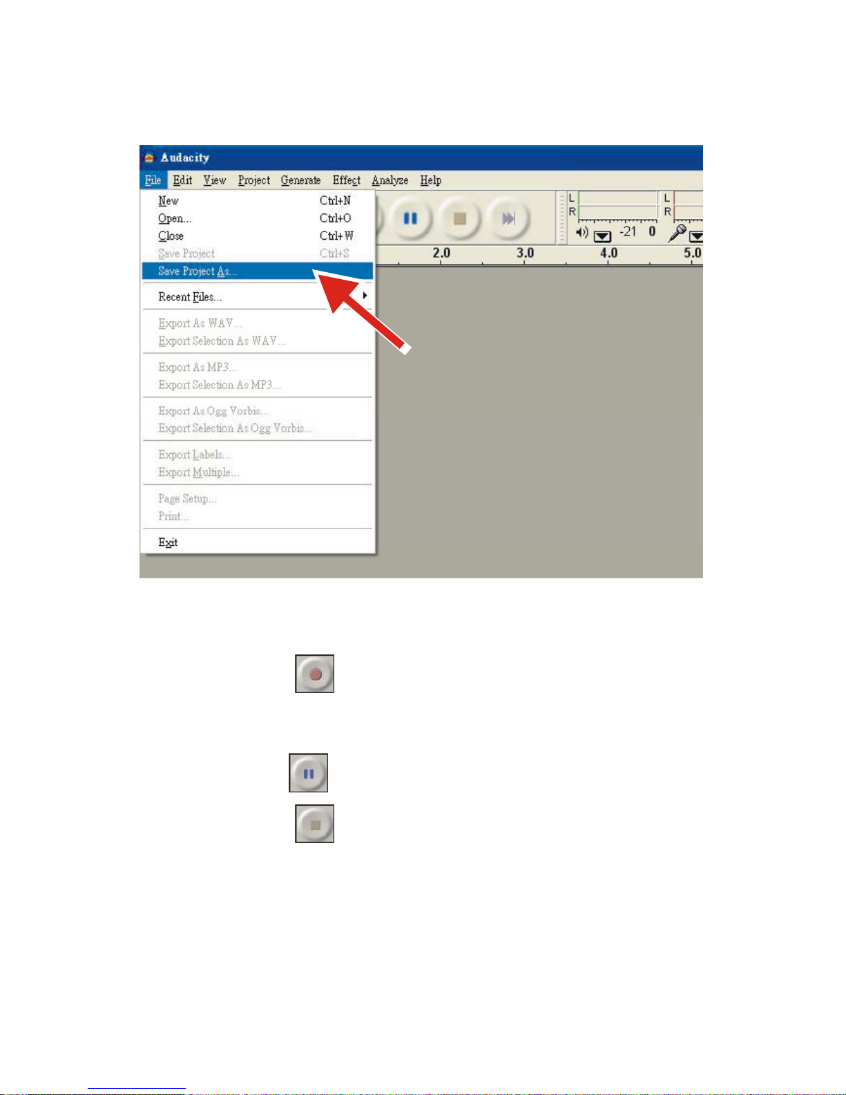
1. Saving a project
Audacity writes all the changed and recorded audio to a directory called Projectname_data, which is located
right where you saved the project file itself.
Thus, select Save project as from your Audacity File tab and choose a location and filename for your project.
Please note that when you startup Audacity fresh, only the “Save As...” menu option is available.
2. How to record
Set your USB turntable up to play the song or album you want to record.
Click on the red Record button
to begin recording.
Lower tone arm on USB turntable onto album and track you want to record.
Click on the blue Pause button
to pause the recording. Press it again to continue.
Click on the yellow Stop button.
That's it. You can now play around with your recording and explore the editing capabilities of Audacity. Remember that you
can use the Undo function almost without limits while the project is open.
NOTE: CD's cannot be burned directly from the Audacity application. Other CD burning applications should be used.
8

SPECIFICATION
GENERAL
Model: Vinyl USB 5C
Professional Belt Drive USB T urntable
Dimensions: 450(W) x 350(D) x145 (H) mm
Weight: 4.0Kgs
Power supply: Dual Voltage: AC 115V~60Hz/230V~50Hz, User Selectable
Power consumption: 8W
Standa rd test condition: Ambient Temperature: 23 +/- 2 degC
Relative Humidity: 65% +/- 5%
NOTE: Measurements can be carried out between 5 degC to 35 degC and 45% to 85% relative humidity.
TURNT ABLE SECTION:
Type 2-speed full manual
Motor DC motor
Driving Method Belt drive
Turntable Platter 330mm dia. Plastic
Speeds 33
1
/3 and 45rpm
Wow and Flutter Less than 0.25% WRMS (JIS WTD) with 33
1
/3 rpm
S/N Ratio More than 50dB (DIN-B)
Pitch Controls +/- 10%
Starting Time Less than 1 sec with 33
1
/3
Braking Time Less than 1 sec. with 33
1
/3
Time for Speed Change Less than 1 sec. from 33
1
/3 to 45 rpm
Less than 1 sec. from 45 to 33
1
/3 rpm
Speed tolerance at pitch=0 Within +/-1.3%
USB Function USB rec. Function
A/D, D/A 16BIT 44.1KHz or 48KHz USB SELECTABLE
Computer interface USB 1.1 compliant, WINDOWS XP or MAC OSX
TONEARM SECTION:
Type Static balanced S-shaped tonearm with detachable headshell
Effective Arm Length 220 mm
Tracking Error Angle Less than 3 degree
Applicable Cartridge Weight 6~10g
Anti-skating Range 0-4g
Phono Output Level 1.5~3.6 mV at 1KHz 5cm/sec (HP-4005)
Line Output Level 90~216mV at 1KHz 5cm/sec (HP-4005)
Frequency Response 20Hz-20KHz
Channel Separation More than 15dB
Channel Balance Within 2.5dB at 1KHz
Needle Pressure range 3~4g
High of cue(first track) 6~10.5mm
Descend of cue 1~3sec
EQ AMP
Output 150mV +/-4dB (IN: 2.5 mV 1KHz)
RIAA 20Hz~20KHz +1/-3dB (IN: 1.5 mV 1KHz)
9

INFORMATION DE SÉCURITÉ IMPORTANTE
1. Toutes les intructions de sécurité et précautions doivent être lu avant l’utilisation de l’appareil.
2. Retenir les instructions. Les instructions de sécurité et opérations doivent être retenu pour de future référence.
3. Faire attention à l’avertissent. Vous deve z adhérer à tous les avertissements et opération d’emploi
4. Suivre les instructions. Toutes les opérations et instructions doivent être suivi.
5. Eau et l’humidité. L’appareil ne doit pas être placé près de l’eau, par exemple, près d’une baignoire, cuisine, sale
d’eau, piscine, endroit humide.
6. Chariot et stand. L’appareil doit être utilise sur un stand recommander par le fabriquant. L’appareil doit
être manipulé avec soin. Un arrêt trop brusque ou une force excessive peu causer des dommages à
l’appareil.
7. Montage au mur ou plafond. Le produit peu être monté sur un mur ou un plafond seulement si c’est recommander par
le fabriquant
8. Chaleur-L’appareil doit être situé loin des sources de chaleur comme radiateur, cuisinière ou tout autre appareil qui
produit de la chaleur .
9. Sources d’alimentation. Ce produit ne peu être utilise uniquement que sur une source d’alimentation adapté à l’appareil.
Vous trouverez les informations sur l’étiquette de l’appareil. Si vous n’êtes pas sur de la tension secteur de votre
habitation, consultez la compagnie d’électricité local.
10. Protection cordon d’alimentation. Le cordon d’alimentation doit être placé de façon à ce que les gens ne marche pas
dessus ni qu’ils se prennent les pieds dedans.
11. Nettoyage - l'appareil devrait être nettoyé seulement comme recommandé par le fabricant. Nettoyer en essuyant avec
un tissu légèrement humidifié avec de l'eau. Éviter de mettre de l'eau à l'intérieur de l'appareil
12. Le cordon de secteur. Le cordon secteur de l'appareil devrait être débranché de l’alimentation une fois laissé inutilisé
pendant une longue période
13. Entrée d'objet et de liquide - le soin devrait être pris de sorte que les objets ne tombent pas à l’intérieur et des liquides
ne soient pas renversés dans l’appareil par les ouvertures
14. Dommages exigeant le service - l'appareil devrait être entretenu par le personnel de servi ce qualifié quand : Le cordon
d’alimentation ou la prise a été endommagée ; ou Les objets sont tombés, ou le liquide a été renversé dans l'appareil ;
ou L'appareil a été exposé à la pluie ; ou L'appareil ne semble pas fonctionner normalement ou ne montre pas un
changement marqué d'exécution ; ou l'appareil est tombé, ou couvercle a été endommagée
15. Entretien - l'utilisateur ne devrait essayer aucun entretien à l'appareil au delà de cela décrit dans les consignes
d'utilisation. Tout l'autre qui entretient devrait être mentionné a qualifié le personnel de service
16. Ventilation - des fentes et les ouvertures dans le coffret sont données pour la ventilation et pour assurer l'opération
fiable du produit et pour la protéger contre la surchauffe, et ces ouvertures ne doivent pas être bloquées ou couve rtes.
Les ouvertures devraient ne jamais être bloquées en plaçant le produit sur un lit, le sofa, la couverture, ou toute autre
surface semblable. Ce produit ne devrait pas être placé dans une installation intégrée telle qu'une bibliothèque ou le
support à moins que la ventilation appropriée soit les instructions du fabricant ont été respectées.
17. Les accessoires - ne pas utiliser les accessoires non-recommandés par le fabricant de produit comme ils peuvent
causer des risques.
18. Des accessoires - ne pas placer ce produit sur un chariot, un stand, un trépied, ou une table instable. Le produit peut
tomber, endommageant des dommages sérieux à un enfant ou à un adulte, et sérieux dommage sur le produit. Porter
seulement avec un chariot, un stand, un trépied, ou une table recommandée par le fabricant, ou vendue avec le
produit. N'importe quel support du produit devrait suivre les instructions du fabricant, et devrait utiliser un accessoire
de support recommandé par le fabricant.
19. Foudre - pour la protection supplémentaire pour ce produit pendant une foudre, ou quand elle est laissée sans
surveillance et inutilisée pendant de longues périodes, débrancher de la prise murale et débrancher le système
d'antenne ou de câble. Ceci empêchera des dommages au produit dû aux montées subites de foudre et de ligne à
haute tension.
20. Pièces de rechange - quand des pièces de rechange sont exigées, être sûr que le technicien de service a employé
des pièces de rechange indiquées par le fabricant ou a les mêmes caractéristiques que la partie originale. Les
substitutions non autorisées peuvent avoir comme conséquence le feu, la décharge électrique, ou d'autres risques
21. Le contrôle de sûreté - sur l'accomplissement de tout le service ou réparations à ce produit, demandent au technicien
de service d'exécuter des contrôles de sûreté pour déterminer que le produit est en condition de fonctionnement
appropriée.
22. Fondre ou polarisation - ce produit peut être équipé d'une ligne alternance-courante polarisée prise (une prise ayant
une lame plus large que l'autre). Cette prise s'adaptera dans la de prise de courant seulement. C'est un dispositif de
sûreté. Si vous ne pouvez pas insérer la prise entièrement dans la sortie, essayer de renverser la prise. Si la prise
s'adapte, contactent votre électricien pour remplacer votre sortie. Ne pas défaire le but de sûreté de la prise polarisée.
23.
Le cordon d’alimentation P devrait être conduite de sorte qu'elles ne soient pas susceptibles d'être marché dessus ou
pincées par des articles placés sur ou contre eux, porté une attention particulière au cordon dans la correspondance
des prises, les réceptacles de convenance, et le point où ils sortent de l'appareil.
10
Avertissement: Pour réduire les risques de chocs électriques, ne pas
ouvrir l’appareil. Referez-vous à un personnel qualifié
Ce logo vous indique la présence de “tension dangereuse”, il y a risque de choc électrique.
Ce logo vous indique des opérations de maintenance importante.
CAUTION
Pour empêcher les décharges électriques, ne pas utiliser cette prise polarisée avec un cordon de prolongation,
Empêcher tout introduction d’objet dans le réceptacle pour éviter tout risque d’incident.
INE VOLTAGE SELECTION
Juste pour le mode double tension seulement ! Puisque les alimentations
d'énergie changent d’un l'endroit à un autre nous avons incorporé une
alimentation d'énergie sélectionnable.
La tension désirée peut être placée avec le commutateur de SÉLECTEUR de
TENSION placé sous le plateau. (utiliser un tournevis plat). Ne pas forcer le
commutateur de SÉLECTEUR de TENSION comme ceci peut endommager. Si le
commutateur de SÉLECTEUR de TENSION ne se déplace pas sans à-coup,
contacter svp un technicien qualifié de service.
AVANT L’UTILISATION
Vérifier les pièces suivantes incluses dans le paquet avec l'unité principale:
Plateau
Slipmat
Tête
Cartouche
Cable USB
Contre poids
Disque
Câble RCA
Adaptateur 45 rpm
Manuel ’utilisation
Couvercle antipoussière transparent
Très important !
Ne pas oublier d'attacher la courroie en caoutchouc au moteur pour un
fonctionnement correcte. Après placement du plateau tourne-disques sur le
tourne-disques par l'axe central, déplacer une des grandes fenêtres sur le plateau
au bon coin supérieur. Attacher la couroie en caoutchouc autour du moteur. (La
courroie en caoutchouc est déjà attachée au dessous du plateau de plateau
tourne-disques.)
Notes:
1. Ne pas relier la prise de courant alternatif avant que l'assemblage ait été accomplie.
2. Avant de rétablir le courant, s'assurer que de nouveau tous raccordements et réglage de tension sont corrects.
Couper toujours le courant en se reliant ou en débranchant.
3. Lire ce manuel soigneusement avant d'utiliser l’apareil. Être sûr de stocker le manuel dans un endroit sûr pour une
future consultation.
DO NOT OPEN
RISK OF ELECTRIC SHOCK
11

ASSEMBLAGE
1. Enlever l'unité principale avec l'emballage de la boîte et enlever l'emballage.
2. Placer l'adapteur de 45 t/mn sur l'unité principale.
3. Placer le plateau de plateau tourne-disques sur l'axe central.
4. Placer la feutrine sur le plateau.
5. Installation de la cartouche:
En installant une cartouche, se référer aux consignes d'utilisation de cette cartouche.
Pendant l'installation, attacher le protecteur d'aiguille pour protéger le bout de l’aiguille des dommages.
(a) Relier les fils aux bornes de cartouche. Les bornes de la plupart des cartouches sont de code à couleurs. Relier
chaque fil à la borne de la même couleur.
Blanc L+ canal gauche +
Blue L- canal gauche +
Rouge R+ canal droit +
Vert R- canal droit -
(b) Installer la cartouche sur la tête et la serrer avec des vis de la cartou che.
6. Insérer la tête dans l'embout avant du bras, puis tourner le contre-écrou dans le sens contraire des aiguilles d'une
montre avec la tête tenu fermement horizontalement.
7. Glisser le contrepoids sur le bras. Le tournez légèrement et il vissera sur l'arbre arriè re du bras
8. Ajustement de l’équilibre l’horizontale “zero” et de l'aiguille :
(a) Enlever le protecteur d'aiguille de la tête, ne pas toucher le bout d'aiguille pen dant l'ajustement.
(b) Placer le levier positionnant dans la position abaissée.
(c) Libérer la bride du bras et soulever et le bras du repos pour le libérer.
(d) Tourner le contrepoids jusqu'à ce que le bras soit approximativement équilibré horizontalement (flotte librement).
(e) Rattacher le bras avec la bride bras.
(f) Juger le contrepoids stationnaire avec une main et tourner seul ement l'ann eau d'aiguille-pression p our introdui re le
nombre « 0 » de l'anneau dans l'alignement avec la ligne centrale sur l'arbre arrière bras.
(g) Tourne le contrepoids comprenant l'anneau d'aiguille-pression dans le sens contraire des aiguilles d'une montre
jusqu'à ce que la balance montre la valeur correspondant à la pression de l'aiguille utilisée. Si vous utilisez une
aiguille séparée, suivre svp les instructions du fabricant.
9. Lacer le bouton de commande anti-patinage à la même valeur que la pression d'aiguille
.
10. Installer le cache anti-poussière sur les charnières du cache anti-poussière de l’appareil.
PLACEMENT
Ne pas placer l’apareil dans un endroit où elle sera exposé à la lumière du directe du soleil ou proche d'un appareil de
chauffage.
Ne pas placer l’appareil dans un endroit où il y a humidité élevé ou beaucoup de poussière.
La cartouche peut prendre de légères pressions acoustiques ou vibrations des haut parleurs venant le long du plancher
ou par l'air ayant pour résultat la rétroaction ou le bruit de « FREDONNEMENT ». Trouver un endroit stable sans
vibration.
Les pattes ont des fonctions pour ajuster la taille de l'appareil elle-même. Ajuster les pattes pour stabiliser le corps
principal horizontalement.
12
CONNECTIONS
Avant de relier l'appareil on vous conseille de consulter également votre manuel d'instruction.
IMPORTANT : Être sûr d'arrêter l'appareil avant que vous fassiez des raccordements.
1. Connecter le câble d’alimentation vers une source d’alimentation
2. Connecter le câble Rca vers l’entrée phono de votre table de mixage.
Connecteur de sortie Amplificateur (recepteur)
L (Blanc) Canal Gauche
R (rouge) Canal Droit
Note:
Si ce rapport n'est pas établi ou est lâche, une source d'énergie « ronflement » en résultera.
Vous pouvez également employer une ligne entrée en plaçant le phono/ligne commutateur à l'arrière du plateau
tourne-disques pour rayer.
3. Connect un PC via un cordon Usb.
OPERATIONS
1. T ourne r le commut ateur "Marche/Arrêt" dans le sen s des aiguilles d'une montre pour alimenter l’app areil, l'indicateur d e
vitesse et le bloc d'éclairage stroboscope, qui est placé sous le commutateur "Marche/Arrêt", s'allumera.
2. Placer un disque sur la feutrine. En jouant un disque de 45 t/mn avec un grand trou central, placer l'adapteur de 45 t/mn
sur l'axe central.
3. Régler la vitesse du disque.
4. Enlever la protection de l'aiguille de la tête et puis libérer la bride du bras.
5. Placer le levier en le positionnant dans la position haute.
6. Appuyer sur le bouton start / stop, le plateau du tourne-disques commencera à tourner.
7. Déplacer le bras vers le disque.
8. Placer le levier en le positionnant à la position basse, le bras descendra lentement sur le disque et commencera à
jouer.
9. Quand la lecture est fini, soulever le levier, déplacer l e bras sur la bride du bras.
10. Appuyer sur le bouton start/stop pour arrêter la rotation du plateau. Tourner le commutateur "Marche/Arrêt" dans
le sens contraire des aiguilles d'une montre pour éteindre.
*SUSPENDRE LA LECTURE
Placer le levier en le positionnant « VERS LE HAUT » pendant le jeu, le bout d'aiguille de la cartouche sera soulevé du
disque.
PC
Set thePHONO/LINE
swi tch to “LI NE” .
Set thePHONO/LINE
switch to“PHONO” .
13
CHANGER LA VITESSE
T ant que la commande de pitch est en position centrale « détente », le plateau tourne-disques est actionnée à la vitesse
choisie.
La vitesse peut être augmentée ou diminuée de 10% par la commande de pitch.
Un ajustement incorrect fait tourner la plateau tourne-disques extrêmement lent ou rapide.
Les points de stroboscope au bord du plateau tourne-disques sont employés pour la surveillance de la vitesse
MAINTENANCE
Nettoyer l'aiguille périodiquement avec une brosse molle pour empêcher l'accumulation de la poussière.
Quand le bruit devient saturé ou bruyant, vérifier l'aiguille. Si l'aiguille est tordu, la remplacer avec une neuve.
De temps en temps, le cache anti-poussière et le coffret de plateau tourne-disques devraient être essuyés vers le ba s
avec un tissu mou et sec.
Des matériaux volatils ne devraient pas être employés, comme : alcool, diluant, benzin etc. Ils peuvent enlever la
peinture ou endommager la façade.
VUE D’ENSEMBLE DES COMMANDES
1. Adaptateur 45 rpm
Cet adapteur te permet de jouer la norme 33 tr des
disques de vinyle avec de grands trous centraux.
Placer l'adapteur sur l'AXE CENTRAL 33 tr des
disques.
2. Plateau de plateau tourne-disques
Ce plateau se relie directement à l'axe central. L'axe du
plateau et du centre tient le centre du disque vinyle
parfaitement. Le plateau tourne également le disque à
une vitesse cohérente.
3. Indicateurs de stroboscope
Le plateau a quatre rangées des indicateurs. Ces
indicateurs sont employés pour détailler visuellement de
diverses étapes de lancement. Les indicateurs sont
illuminés par la lampe pilote d'indicateur stroboscope.
Chaque rangée peut sembler s'élever toujours à
différents niveaux de lancement. Note : L'utilisation de
l'éclairage fluorescent lourd directement au-dessus du
plateau tourne-disques défera la Lampe stroboscope.
La lampe pilote affectent l'exactitude d'indicateur.
1
3
4
6
5
7
13
14
15
16
17
18
9
8
11
12
10
23
21
22
19
2
20
14

4. Axe central
Cet axe maintient les disque stables et a centre sur le
plateau.
5. Lampe pilote indicateurs de stroboscope
Cette lampe particulièrement conçue pour palpiter un
faisceau de lumière aux indicateurs stroboscope pla tea u
tourne-disques.Ceci donnera l'illusion que les
indicateurs ne tournent pas à certaines vitesses.
6. Power Switch
C'est un commutateur d’alimentation rotatif. Pour
allumer tourner le commutateur dans un sens horaire.
Pour arrêter tourner commutateur dans le sens
anti-horaire.
7. Start/Stop Button
Quand l'appareil est allumé le plateau ne commencera
pas automatiquement à tourner. Appuyer sur le bouton
une fois pour engager le haut du moteur de couple et
tourner le plateau, appuyer une seconde fois pour
arrêter le plateau.
8. Headshell
Le tête inclus est employé pour relier votre aiguille au
bras de tonalité.
9. Headshell Locking Nut
Après fixation de la tête au bras, cet écrou de
fermeture tiendra solidement le tête sur le bras.
10. S-Shaped Tone Arm
Le bras est le mécanisme qui tient la tête et l'aiguille,
lui permettant de glisser à travers un disque.
11. 33-RPM Speed Select Button
Appuyer ce bouton ça tournera le plateau à 33 tours
par minute (RPMs). Une LED rouge s’éclaire quand
cette fonction est activée.
12. 45- RPM Speed Select Button
Appuyer ce bouton il tournera le plateau à 45 RPMs.
Une LED rouge s’éclaire quand cette fonction est
activée.
13. Pitch Control Slider
Ce curseur est utilisé pour ajuster le pourcentage de
pitch (vitesse de plateau).
14. Tone Arm Lever
Ce levier est employé pour élèver sans risque le bras
de tonalité au-dessus de la surface du disque sans
mettre en danger celle ci.
15. Arm Rest Clamp and Rest
Utiliser pour tenir sans risque le bras en position
pendant le non-usage et le transport.
16. Anti-skate Knob
L'anti-patinage applique la force centrifuge au bras
pour empêcher sauter à l'extérieur à travers le disque
dû à la cause de force centrifuge par rotation de
plateau. La valeur d'anti-patinage devrait être
également à cela de la pression de contrepoids
d'aiguille.
17. Stylus-Pressure Ring
La balance de contrepoids doit faire face vers le DJ.
18. Extra Stylus Holder
Ceci coupé a été conçu pour stocker sans risque un
headshell supplémentaire d'aiguille.
19. Counterweight
Utiliser le contrepoids pour équilibrer le bras de
tonalité et pour ajuster la pression d'aiguille.
20. Cache poussière
21. USB Socket (USB cable limit within 3m)
Après avoir relié la plateau tourne-disques à
l'ordinateur par l'intermédiaire de l'USB, vous pouvez
enregistrer votre vinyle à votre disque dur en utilisant le
logiciel inclus.
22. Phono/Line Selector
Ce commutateur est utilisé pour changer le mode ligne
ou phono.
23. RCA output Jacks
La sortie peut commuter en LIGNE ou PHONO. Par
exemple: Ces jacks sont employés pour envoyer un
bas signal de sortie de niveau de « phono » de tension
aux jacks d'une entrée de « phono » de mélangeurs.
Des plateaux tourne-disques devraient être reliées
aux entrées de « Phono » sur un mélangeur. Le jacks
RCA coloré par rouge représente le bon canal entré et
le blanc représente l'entrée gauche de canal.
15

LOGICIEL AUDACY
Logiciel gratuit: Audacity sous licence GNU General Public License (GPL). Pour plus d’information consulter le site
internet:http://audacity.sourceforge.net
* Please ensure you have installed the software before starting.
PROCEDURE ET REGLAGE
1. Connectez l’appareil à une source d’entrée
2. Connectez le câble USB vers l’ordinateur
3. Installez le logiciel d’enregistrement Audacity
4. Ouvrir le programme Audacity
5. Sélectionner Préférence dans le menu edit du logiciel Audacity.
6. Sélectionner Audio I/O en haut à gauch e.
En lecture, sélectioner votre carte son interne
En enregistrement, sélectionner le CODEC Audio USB
En enregistrement, sélectionner 2 (stereo).
Vérifier la boite, lire d’autre piste tout en enregistrant une nouvelle piste
Vérifier la boite, logiciel.
16

Enregistrer des albums avec Audacity
1. Sauver un projet
Audacity écrit tout changement et enregistrement dans un repertoire appelé Projectname_data, qui est situé ou
vous avez enregistré le projet.
Choisir suver le projet comme à partir de votre étiquette de dossier et choisir un endroit et un nom de fichier pour
votre projet.
Veuillez noter quand vous démarré Audacity, seul ement « sauver sous… » dans l'option de menu est disponible.
2. Comment enregistrer
Placer votre tourne-disques USB jusqu'à la lecture de la chanson ou l'album que vous voulez enregistre r.
Clic sur le bouton record rouge pour commencer à enregistrer.
Abaisser le bras sur le plateau tourne-disques USB sur l'album et la piste que vous souhaité enregistrer.
Clic sur la touche attente bleue pour faire une pause à l'enregistrement.
Le presser encore pour continuer.
Clic sur la touche "ARRÊT" jaune.
Voilà. Vous pouvez maintenant jouer avec votre enregistrement et explorer les possibilités de édition de Audacity. Se rap p el er
que vous pouvez employer la fonction de annulation presque sans limi tes tandi s que le projet est o uvert.
NOTE : Des CD ne peuvent pas être gravé directement de l'application Audacity. D'autres applications de gravure de CD
devraient être employées.
17

CARACTERISTIQUES
GENERAL
Model: Vinyl USB 5C
Tourne disque Professionnel USB entrainement à courroie
Dimensions: 450(W) x 350(D) x145 (H) mm
Poids: 4.0Kgs
Alimentation: Double Voltage: AC 115V~60Hz/230V~50Hz, Sélectionnable
consomation: 8W
Condition de test standard: Temperature ambiant: 23 +/- 2 degC
Taux d’humidité: 65% +/- 5%
NOTE: Mesuré à 5 degC to 35 degC and 45% à 85% taux d’humidité.
SECTION TOURNE DISQUE:
Type 2-vitesse manuel
Moteur Moteur DC
Mode d’entrainement Entrainement couroie
Plateau 330mm dia. Plastic
Vitesse 33
1
/3 and 45rpm
Wow et Flutter Moins de 0.25% WRMS (JIS WTD) avec 33
1
/3 rpm
S/N Ratio Moins de 50dB (DIN-B)
Pitch +/- 10%
Temps de démarage Moins de 1 sec avec 33
1
/3
Temps de freinage Moins de 1 sec. avec 33
1
/3
Temps de changement
de vitesse
Moins de 1 sec. de 33
1
/3 to 45 rpm
Moins de 1 sec. de 45 to 33
1
/3 rpm
Tolerrance de vitesse pitch=0 avec +/-1.3%
Fonction USB USB rec. Fonction
A/D, D/A 16BIT 44.1KHz ou 48KHz USB SELECTIONNABLE
Interface informatique USB 1.1, WINDOWS XP ou MAC OSX
SECTION BRAS:
Type Static balanced S-shaped tonearm with detachable headshell
Longeur du bras 220 mm
Angle d’erreur Less than 3 degree
Poids de la cartouche 6~10g
Anti-skating Range 0-4g
Phono Output Level
Line Output Level
1.5~3.6 mV at 1KHz 5cm/sec (HP-4005)
90~216mV at 1KHz 5cm/sec (HP-4005)
Fréquence de Réponse 20Hz-20KHz
Séparation de canal More than 15dB
Canal Balance Within 2.5dB at 1KHz
Pression 3~4g
High of cue(first track) 6~10.5mm
Descente 1~3sec
EQ AMP
Sortie 150mV +/-4dB (IN: 2.5 mV 1KHz)
RIAA 20Hz~20KHz +1/-3dB (IN: 1.5 mV 1KHz)
18

WICHTIGE SICHERHEITSHINWEISE
1. Lesen Sie bitte alle Warn- und Bedienungshin weise sorgfältig durch, bevor Sie dieses Gerät in Betrieb nehmen.
2. Bewahren Sie diese Bedienungsanleitung für evtl. später auftauch ende Fragen sorgfältig auf.
3. Entfernen Sie bitte nicht die Warnhinweise am Gerät.
4. Befolgen Sie bitte alle Hinweise in dieser Bedienungsanleitung genau.
5. Nutzen S ie dieses Gerät niemals in der Nähe von feuchten Stellen wie z.B. Waschbecken, Badewannen ode r Teichen und
Seen.
6. Dieses Gerät sollte nur in solchen Einbauhalterungen e ingebaut werden, die der Hersteller zum Transport
empfiehlt. Achten Sie beim Transport darauf, dass das Gerät ausreichend gesichert ist! Unebene
Oberflächen oder plötzliche Bremsbewegungen können. zum Umkippen der Einbauhalterung, worin das
Gerät eingebaut wurde, führen und es beschädigen.
7. Der Einbau in eine Einbauhalterung darf nur so vorgenommen werden, wie es vom Hersteller vorgesehen i st.
8. Das Gerät muss von anderen, Wärme verursachenden Geräten wie Endstufen, Heizkörpern usw. ferngehalten werden.
9. Dieses Gerät darf nur mit der Betriebsspannung versorgt werden, die der Hersteller vorsieht. Wenn Sie sich nicht
sicher sind, ob Ihr Stro mnetz für di eses Produkt geei gnet ist, kontaktieren Sie bitte Ihren Fachhändler. Bei Geräten, die
batteriebetrieben werden, nehmen Sie sich die entsprechende Bedienungsanleitung zur Hilfe.
10. Dieses Produkt verfügt möglicherweise über einen Schutzkontakt Stecker, der nur in einer Position in die Steckdose
passt. Dies ist ein Sicherheitsmerkmal zur Erdung des Produkts. Entfernen Sie niemals Bauteile vom Stecke r, damit er
besser in die Steckd ose passt.
11. Achten Sie im Betrieb darauf, dass das Stromanschlusskabel nicht eingeklemmt oder eingeschnitten werden kann.
Verlegen Sie das Kab el immer so, dass es von keinen anderen Geräten beschädigt werden kann.
12. Reinigung des Gerätes: Reinigen Sie das Gerät nur wie vom Hersteller vorgesehen. Nutzen Sie hierfür einen weichen,
leicht feuchten Lappen und wischen Sie das Gerät damit vorsichtig ab. Achten Sie darauf, das s n iemals Feu chtigkeit ode r
gar Flüssigkeit ins Geräteinnere gelangen kann.
13. Bevor Sie Wechselstromgeräte nach einer Reparatur wieder in Betrieb nehmen, messen Sie an allen metallischen
Gehäuseteilen den Widerstand. Er sollte mehr als 100.000 Ohm betragen.
14. Wenn Sie das Gerät für längere Zeit nicht benutzen wolle n, ziehen Sie den Netzstecker vom S tromnetz ab.
15. Achten Sie darauf, dass das Gerät nicht in Flüssigkeiten fällt, so dass diese ins Gehäuseinnere eindringen könnte.
16. Das Gerät sollte von einem autorisiertem Servicetechniker gewartet werden wenn:
A. Das Stroman schlusskabel oder der Stecker beschädigt wurde oder
B. Das G e rä t heru n t e r g e f a l l e n ist od e r F l ü s s i g k e i t eingedrungen ist oder
C. Das Gerät Regen ausgesetzt war oder
D. Das Gerät nicht fehlerfrei arbeitet bzw. Fehler im Betrieb verursacht oder
E. Das Gerät geworfen wurde oder das Gehäuse si chtbar beschädigt ist.
17. Nehmen Sie keine Reparatur- oder Wartungsarbeiten vor, die nicht ausdrücklich in dieser Anleitung aufgeführt sind.
Kontaktieren Sie für solche Arbeiten immer Ihren Fachhändler.
18. Lüftungsschlitze und Öffnungen am Gerät dienen zur K ühl ung w ähre nd d es Be tri ebes . Di e Kü hllu ftzu fuh r dar f ni emal s
durch zu dicht am Gerät stehende Gegenstände blockiert werden. Achten Sie bei der (Fest-) Installation darauf, dass
eine ausreichende Kühlluftzufuhr stets gewährleistet ist. Nutzen Sie das Gerät nicht auf Gegenständen wie z.B. Sofa
oder Bett, da die s die Lüftu ngsschlitze block iert und verdreckt. Sollten die Lüftungsschlitze verstaubt oder verdreckt sein,
reinigen Sie diese bitte.
19. Benutzen Sie kein Zubehör, welches nicht vom Hersteller empfohlen wurde. Es kön nte Schäden verursachen.
20. Benutzen Sie dieses Gerät nicht auf Gegenständen wie wackeligen Tischen oder Ähnlichem. Durch ungewolltes
Herunterfallen kann nicht nur das Gerät stark beschädigt oder Zerstört werden, sondern es können auch Personen
oder Kinder verletzt werden. Bauen Sie das Gerät nur so auf und ein, wie es vom Hersteller empfohlen wird oder in
Einbauhalterungen die mit diesem Gerät angeboten oder verkauft werden. Fragen Sie ggf. Ihren Fachhändler nach
geeigneten Einbauhalterungen.
21. Zu Ihrer eigenen Sicherheit trennen Sie das Gerät bei Gewitter oder langen Nutzungspausen vom Stromnetz. Somit
gewährleisten Sie, dass auch andere Geräte nicht in Mitleidenschaft gezogen werden und das Gerät lange und
zuverlässig funktioniert.
22 . F alls E rsatz teile erfor derli ch sin d, ach ten Sie dara uf, dass nur vom Hersteller empfohlene oder baugleiche Tei le ve rw en det
werden. Lassen Sie den Einbau nur durch Ihren Servicetechniker durchführen.
23. Kontaktieren Sie zur optimalen Sicherheit von Zeit zu Zeit Ihren Fachhändler und lassen Sie ihn einen
Sicherheitscheck durchführen. Solche kurzen Checks sind in der Regel immer kostenlos und tragen erheblich zur
Sicherheit im Betrieb bei.
19

ACHTUNG: Um das Risiko eines elektrischen Stromschlags zu
minimieren, entfernen Sie bitte keine Gehäusedeckel! Gefährliche
Betriebsspannung im Gehäuseinneren kann lebensgefährlich für den
Menschen sein. Überlassen Sie evtl. Reparaturen ausschließlich
qualifiziertem Fachpersonal!
Um einen elektrischen Schlag zu vermeiden, öffnen Sie niemal s das Gerät! Hohe Betriebsspan nung im Innern
des Gerätes kann für den Menschen lebensgefährlich sein! Schützen Sie das Gerät unbedingt vor
Feuchtigkeit!
Dieses Symbol weist Sie darauf hin, dass der Betrieb dieses Gerätes unbedingt das Lesen der
Bedienungsanleitung erfordert. Unsachgemäße Anwendung birgt Gefahren für Mensch und Umwelt und kann
zu schweren gesundheitlichen Schäden führen.
ACHTUNG
Um einen lebensgefährlichen Stromschlag zu verhindern, nutzen Sie bitte nur Verlängerungskabel zum Anschluss an
das Stromnetz, wenn diese exakt passgenau sind.
SPANNUNGSVERSORGUNG
J Die Netzspannung sollte bei den Geräten bereits voreingestellt
sein. Überprüfen Sie jedoch vor dem Ersteinsatz, ob vielleicht
versehentlich der Spannungswahlschalter falsch geschaltet ist.
Ändern Sie niemals die Spannungsvorwahl.
Ein Umschalten kann unter Umständen zu schweren
Beschädigungen führen.
Sollte der Spannungswahlschalter defekt sein, kontaktieren Sie
bitte einen Fachmann zur Überprüfung.
VOR DEM BENUTZEN
Bitte überprüfen Sie, ob folgende Teile im Lieferumfang enthalten sind:
Plattenteller
Rutsch-Matte
Headshell (Systemhalte r)
Patrone
USB-Kabel
Gegengewicht
Diskette
Audio-Kabel
Durchsichtige Staubdecke
45rpm Adapter
Bedienungsanleitung
Achtung!
Verbinden Sie unbedingt den Antrie bsriemen mit dem Motor, damit der Plattenspieler
richtig funktioniert! Nachdem Sie den Plattenteller auf d en Plattenspueler gelegt haben,
drehen Sie den Teller, bis eines der beiden Sich tfenster Über dem Antriebsmotor des
Plattenspielers liegt. Befestigen Sie nun den Riemen an der Antriebswelle des Motors.
(Der Riemen ist bereits an der Unterseite des Plattentellers befestigt.)
Anmerkung:
1. Verbinden Sie das Gerät nicht eher mit dem Stromnetz, bevor nicht alle Vorbereitungen abgeschlossen sind.
2. Gehen Sie vor dem einschalten des Gerätes sicher, dass alle Verbindungen korrekt sind und die richtige Volt
Spannung a m GerVt eingestellt ist. Schalten Sie das Gerät immer erst ab, wenn Sie es vom Stromnetz trennen.
3. Lesen Sie diese Bedienungsanleitung sorgfältig durch, bevor Sie das Gerät benutzen und bewahren sie für spatter
auftauchende Fragen gut auf.
DO NOT OPEN
RISK OF EL ECT RIC SHOCK
20

Zusammenbau
1. Nehmen Sie das Gerät aus der Verpackung und entfernen sie die Schutzfolie.
2. Legen Sie den 45 U/min-Adapter an seinen vorgesehnen Platz.
3. Stellen Sie zunächst den Betriebsspannungsschalter (auf der Oberseite des Gehäuses, unter dem Plattenteller) auf
die örtliche Netzspannung ein.
4. Setzen sie nun den Plattenteller mit der Rutschmatte auf das Gehäuse auf.
5. Montage des Tonabnehmersystems: Richten Sie sich für den korrekten Anschluss eines Tonabnehmersystems nach
dessen Anleitung und lassen Sie während der Montage die Schutzkappe so lange wie möglich montiert, um den
sensiblen Tonabnehmer nicht zu beschädigen.
(a) verbinden Sie die Kabel des Systems mit dem Systemhalter. Die meisten Halter und Systeme sind farblich
gekennzeichnet, so dass Sie nur die Farben übereinstimmend zuordnen m üssen.
Weiss (L+) Links +
Blau (L-) Links –
Rot (R+) Rechts +
Grün (R-) Rechts –
(b) Befestigen Sie den Tonabnehmer mit den beiden Schrauben am Systemhalter und ziehen Sie die Schrauben mit
einem passenden Schraubenzieher nicht zu fest an.
6. Befestigen Sie den Systemhalter mit dem System am Tonarm und ziehen Sie die Überwurfmutter des Tonarms
handfest an.
7. Setzen Sie das Gegengewicht auf und drehen Sie im Uhrzeigersinn auf den Tonarm auf.
8. Einstellen des korrekten Auflagegewichtes des Tonabnehmers.
(a) Nehmen Sie die Schutzkappe vom Tonabnehmer. Berühren Sie die Nadel nicht mit der Hand.
(b) Stellen Sie den Lift-off Hebel um auf AB.
(c) Lösen Sie den Tonarm aus der Arretierung.
(d) Stellen Sie das Gewicht so ein, dass der Tonarm horizontal ausbalanciert ist und in keine Richtung kippt.
(e) Legen Sie den Arm zurück auf die Halterung und befestigen Sie ihn mit der Arretierung.
(f) Halten Sie das Gegengewicht mit einer Hand fest und drehen Sie nur den Ring mit der Skala, so dass die 0 nach
oben zeigt.
(g) Drehen Sie jetzt das Gewicht und den Anzeigering um den gewünschten Einstellwert in Richtung des
Tonabnehmers. Falls gewünscht können Sie das Gewicht nun in der aktuellen Position durch anziehen der
Befestigungsschraube fixieren.
9. Stellen sie das Anti-skating Rad auf denselben Wert ein.
10. Setzen Sie die Scharniere der Staubschutzabdeckung in die vorgesehenen Ha lterungen ein.
Aufstellen des Gerätes
Stellen Sie das Gerät an einem trockenen Ort auf, der nicht dauerhaft und direkt von der Sonne beschienen wird.
Verwenden S ie das Gerät nicht in besonders staubiger Umgebung.
Auf schwingenden Böden wie z.B. alten Dielenböden, wird jeder Schritt von der Nadel als Vibration wahrgenommen
und über die Anlage als Störgeräusch übertragen. Stellen Sie das Gerät daher an einem möglichst vibrationsarmen
Ort auf.
Die Füße des Plattenspielers sind verstellbar, so dass das Gerät bei einem unebenen Untergrund horizontal
ausgerichtet werden kann.
21

Anschluss des Plattenspielers
Bs Gerät anschließen, empfehlen wir dringend, auch die Anleitungen Ihrerbereits vorhandenen Geräte zu lesen, die Sie
zusammen mit diesem Gerät nutzen möchten.
WICHTIG:
Gehen Sie sicher, dass immer alle Geräte abgeschaltet sind, bevor Sie Anschlüsse verändern.
1. Verbinden Sie das Stromkabel mit dem Plattenspieler und dem Stromnetz.
2. Verbinden Sie das RCA Kabel mit dem PHONO Eingang Ihres Mixers/Verstärkers.
Ausgänge Mischpult (Stereo Anlage)
L (Weiß) Linker Kanal
R (Rot) Rechter Kanal
ANMERKUNG:
Wenn diese Verbindung nicht besteht oder si e zu locker ist, kann es zu einer “Brummschleife” kommen.
Wenn Sie am Plattenspieler den Phono/Line Schalter auf Line stellen, können Sie auch einen Line Eingang am
Mischpult auswählen.
3. Verbinden Sie den PC mit Hilfe de s USB Kabels.
BEDIENUNG
1. Drehen Sie den Einschalt-Knopf im Uhrzeigersinn um das Gerät einzuschalten. Das Stroboskop und die
Geschwindigkeitsanzeige leuchten daraufhin auf.
2. Legen sie eine Schallplatte auf die Rutschmatte des Plattentellers.
3. Stellen Sie die Gesch win digkeit entsprechend der Schallplatte ein.
4. Entfernen Sie die Schutzkappe vom Tonabnehmer und lösen Sie die Arretierung des Tonarmes.
5. Heben sie den Tonarm mit dem Lift-off Hebel an.
6. Drücken Sie Start um den Plattenteller in Bewegung zu setzen.
7. Schwenken Sie den Tonarm über die gewünschte Stelle auf der Platte.
8. Lassen Sie den Tonarm mit dem Lift-off Hebel herunter. Er sinkt langsam auf die Platte und beginnt mit der
Wiedergabe.
9. Wenn die Schallplatte zu ende ist, Heben Sie den Tonarm mit de m Lift-off Hebel an und setzen Sie ihn zurück in die
Halterung.
10. Drücken Sie die Start/Stop Taste um den Plattenteller anzuhalten und Drehen Sie den EIN/Aus-Schalt-Knopf gegen
den Uhrzeigersinn, um den Plattenspieler auszuschalten.
*WIEDERGABE UNTERBRECHEN:
Heben Sie den Tonarm mit Hilfe des Hebels für die Tonarmstütze an, um die Wiedergabe kurz zu unterbrechen.
PC
Set thePHONO/LINE
swi tch to “LI NE” .
Set thePHONO/LINE
switch to“PHONO” .
22

GESCHWINDIGKEIT WECHSELN
Solange der Pitch Fader mittig steht, spielt der Plattenspieler in der eingestellten Geschwindigkeit ab.
Die Geschwindigkeit kann bis zu +/- 10% erhöht oder verringert werden.
Das ermöglicht auch eine feine Justierung der Geschwindigkeit, wenn der Plattenteller zu schnell oder zu langsam
dreht.
Die Profilpunkte an Rande des Platentellers dienen dabei als Geschwindigkeit sindikator.
WARTUNG
Befreien Sie die Nadel von Zeit zu Zeit mit einer weichen Bürste von Staub.
Wenn der Klang trotz reiner Nadel verkratzt oder schlecht ist, tauschen Sie das Nadelsystem aus.
Reinigen Sie das Gehäuse von Zeit zu Zeit mit einem leicht feuchten Tuch.
Benutzen Sie keine aggressiven Reinigungsmittel wie Benzin oder Verdünnung. Sie können die Farbe und das
Gehäuse angreifen.
Steuerung und Funktionen
1. 45-U/min-Adapter
Mit diesem Adapter können sie 7” Schallplatten mit
großen Loch in der Mitte abspielen.
2. Plattenteller
Der Teller wird direkt auf das Gehäuse aufgesteckt.
3. Markierungen
Die Markierungen auf dem Plattenteller
reflektieren das Licht des Stroboskops und
dienen der korrekten Pitch-Einstellung.
4. Zentrierdorn
Schallplatten werden durch den mittig angeordneten
Dorn zentriert.
1
3
4
6
5
7
13
14
15
16
17
18
9
8
11
12
10
23
21
22
19
2
20
23

5. Stroboskop
Das Stroboskop beleuchtet die Markieru ngen auf dem
Plattenteller und hilft bei der
Geschwindigkeitsregelung.
6. Ein/Aus-Schalter
Zum Einschalten im Uhrzeigersinn drehen, zum
Ausschalten gegen den Uhrzeigersinn drehen
7. Start//Stop-Taste
8. Systemhalter
Die einschraubbare Halterung dient der Befestigung
des Tonabnehmersystems.
9. Verschraubung
Mit dieser Überwurfmutter wird der Systemhalter
befestigt. Diese Mutter wird nur handfest angezogen,
es ist nicht viel Kraft notwendig.
10. Tonarm
Achten Sie bei allen Arbeiten am Tonabnehmer darauf,
dass die hier verbauten Präzisionsteile sehr leicht
beschädigt werden können. Arbeiten Sie mit Gefühl
und nur mit passendem Werkzeug und schützen Sie
die Nadel des Tonabnehmers.
11/12 Geschwindigkeitswahlschalter
Hier können Sie 33 U/min oder 45 U/min einstellen.
13. Pitch-Control Regler
Mit diesem Schieber können Sie die Geschwindigkeit
der abgespielten Schalltplatte während des Betriebs
herauf- oder herabsetzen.
14. Lift-off Hebel
Mit diesem Hebel können sie den Tonarm auf die
Schallplatte absenken oder nach oben anheben, ohne
dabei den Tonarm zu berühren.
15. Transportsicherung
Dieser Clip sichert den Tonarm in der Halterun.
Arretieren Sie den Arm unb edingt mit der
Transportsi cherung, wenn Sie das Gerät an einen
anderen Ort bewegen. Die Nadel des Tonabnehmers
könnte sonst beschädigt werden.
16. Anti-skate Einstellung
Die Anti-skate Einstellung übt leichten Druck nach
Innen auf den Tonarm aus, um entstehenden
Zentrifugalkräften entgegenzutreten. Der eingestellte
Wert sollte grundsätzlich dem eingestellten W ert des
Gegengewichtes am Tonarm entsprechen.
17. Skala des Gegengewichtes
Das Gewicht muss so eingesetzt werden, dass die
Skala in Richtung des DJs zeigt.
18. Reservehalterung
Hier kann ein weiterer Systemhalter sicher und
griffbereit aufbewahrt werden.
19. Gegengewicht
Verwenden S ie das Gegengewicht, um den
Anspressdruck der Nadel auf den für die Nadel
benötigten Wert einzustellen.
20. Aufnahmen für den Staubschutzdeckel
21. USB-Anschluss
Nach dem Anschlu ss des Plattenspielers an Ihren
Computer, können Sie Ihre Schallplatten digitalisieren.
Hierzu können Sie die mitgelieferte Software
AUDACITY verwenden. "Audacity" ist eine kostenlose
Software, lizensiert von GNU General Public License
(GPL). Die maximale Kabellänge für das USB-Kabel
ist in diesem Fall auf maximal 3 Meter limitiert.
22. Phono/Line-Wahlschalter
Wählen Sie hier, in wel chem Modus Sie Ihren
Plattenspieler verwenden möchten. Auf PHONO gibt
der Plattenspieler das Tonsignal analog an eine
Anlage wieder. Steht der Regler auf LINE, wird das
Signal digitalisiert und über den USB-Anschluss
ausgegeben.
23. Cinchanschlussbuchsen
Im Phono-Betrieb wird ein Niedervolt-Phonosignal
ausgegeben. Der Plattenspieler verfügt nicht über
einen eingebauten Vorverstärker, so dass er beim
Anschluss an eine Anlage nicht an den
AUX-Anschluss angeschlossen werden kann, sondern
stets an den PHONO-Anschluss angeschlossen
werden muss.
24

AUDACITY SOFTWARE ÜBERSICHT
Audacity ist eine Gratis-Software, die durch die GNU General Public Lizenz (GPL) lizenziert ist. Weitere Informationen
sowie den Quellcode erhalten Sie auf der Webseite http://audacity.sourceforge.net/
Hinweis: Bitte installieren Sie die Software, bevor Sie das Gerät aufbauen und mit dem Computer verbinden.
PC für die Nutzung von Audacity vorbereiten
1. Verbin den Sie eine Audio Quelle mit der Einheit
2. Verbin den Sie das USB Kabel mit Ihrem Computer
3. Installieren Sie die Audacity Recording Software
4. Öffnen Sie das Audacity Programm
5. Wählen Sie den Punkt Einstellungen aus der Registerkarte Bearbeiten im Audacity Menü aus
6. Wählen Sie im sich nun öffnenden Menüfenster die Registerkarte Audio E/A oben links aus
Unter dem Punkt “Wiedergabe” wählen bei “Gerät” Ihre Soundkarte
Unter dem Punkt “Aufnahme” wählen Sie bei „Gerät“ USB Audio CODEC
Unter “Aufnahme” “Kanäle” wählen Sie bitte 2 (Stereo)
Markieren Sie das Kästchen “Multiplay” bestehende Spuren während Aufnahme einer neuen anhören) mit einem
Haken
Markieren Sie das Kästchen “Software Playthrough” (neue Spuren während Aufnahme mithören) mit einem
Haken
25

Alben mit Audacity aufnehmen
1. Ein Projekt speichern
Audacity schreibt alle Änderungen und Audio-Aufnahmen in einen Ordner namens “IhrProjektname_data”,
welcher exakt dort gespeichert wird, wo Sie auch das Projekt als solches abgelegt haben
Wählen Sie dazu “Projekt speichern unter” aus dem Menü „Datei“ aus und spei chern Sie die Datei an dem Ort ab,
wo Sie das Projekt ablegen wollen
Bitte beachten Sie: Wenn Sie das Programm öffnen, steht zu nächst nur “Projekt speichern unter” zur Verfügung.
2. So startet man eine Aufnahme
Bereiten Sie die Platte, die Sie mit Ihrem USB-Plattenspieler aufnehmen wollen, vor.
Drücken Sie diesen roten Knopf, um die Aufnahme zu starten.
Senken Sie den Tonarm an der Stelle, wo Sie die Aufnahme beginnen wollen, ab.
Klicken Sie auf das Pause Symbol, wenn Sie die Aufnahme unterbrechen möchten.
Klicken Sie auf den gelben Stop-Knopf, wenn Sie die Aufnahme beenden möchten
Das ist schon alles. Sie können sich jetzt in aller Ruhe mit der Audacity Software vetraut machen und Ihre Schallplatten
aufnehmen. Bemerkung: Mit der “Rückgängig” Funktion können Sie nahezu unbegre nzt S chritte zurückset zen und sind so
sehr flexibel bei der Bearbeitung.
Hinweis: CD’s können mit Audacity nicht gebrannt werden. Nutzen Sie hierfür eine entsprechende Brennsoftware.
26

EIGENSCHAFTEN
ALLGEMEIN
Modus: Vinyl USB 5C
Plattenteller mit USB-ausgang
Abmessungen: 450(B) x 350(T) x 145(H)mm
Gewicht: 4,0Kg
Stromversorgung: 115V~60Hz / 230V~50Hz
Stromverbrauch: 8W
Umgebungsbedingungen: Beste Betriebstemperatur: 23 +/- 2 degC
Ideale Relative Luftfeuchtigkeit: 65% +/- 5%
Technische Daten Gehäuse
Typ: 2-speed manuell
Motor Gleichstrom-Motor
Antrieb Riemenantrieb
Drehteller 330mm Durchmesser, Kunststoff
Geschwindigkeiten 331/3 und 45 U/min
Gleichlaufabweichung Weniger als 0.25% WRMS (JIS WTD) bei 331/3 U/min
Rauschabstand Mehr als 50dB (DIN-B)
Pitch-Control +/- 10%
Beschleunigung Weniger als 1 sec auf 331/3
Stoppzeit Weniger als 1 sec. with 331/3
Benötigte Zeiten für den Weniger als 1 sec. from 331/3 to 45 rpm
Geschwindigkeitswechsel Weniger als 1 sec. from 45 to 331/3 rpm
Abweichnung bei Pitch = 0 Innerhalb +/-1.3%
USB-Funktion USB Aufnahmefunktion
A/D, D/A 16BIT 44.1KHz or 48KHz USB-Computerschnittstelle
Kompatibel mit USB 1.1, WINDOWS XP or MAC OSX.
Technische Daten Tonarm:
Typ S-förmiger. Metallarm mit Stellgewicht, Anti-Skating Regler u. Handhebel
Effektive Tonarmlänge 220 mm
Tracking-Abweichung Weniger als 3 Grad
Gewicht des Tonabnehmers 6~10g
Anti-skating Bereich 0-4g
Ausgangsleistung Phono 1.5~3.6 mV bei 1KHz 5cm/sec (HP-4005)
Ausgangsleistung Line-Out 90~216mV at 1KHz 5cm/sec (HP-4005)
Frequenzgang 20Hz-20KHz
Kanaltrennung Mehr als 15dB
Kanal-Balance Innerhalb 2.5dB bei 1KHz
Nadelauflagedruckbereich 3~4g
High of cue(first track) 6~10.5mm
Descend of cue 1~3sec
EQUALIZER AMP
Output 150mV +/-4dB (IN: 2.5 mV 1KHz)
RIAA 20Hz~20KHz +1/-3dB (IN: 1.5 mV 1KHz)
27

BELANGRIJKE VEILIGHEIDSVOORZORGEN
1. LEES EN VOLG DE INSTRUCTIES OP --- Alle veiligheidsvoorzorgen en gebruiksaanwijzingen dienen te worden
gelezen voordat men het product gaat gebruiken.
2. BEWAAR DE GEBRUIKSAANWIJZINGEN---De veiligheid-svoorzorgen en gebruiksaanwijzingen moeten worden
bewaard als referentie voor later.
3. NEEM ALL E WAARSCHUWINGEN IN ACHT --- Alle waarschuwingen op het product en in de gebruiksaanwijzingen
moeten in acht worden genomen.
4. VOLG DE INSTRUCTIES OP – Alle instructies voor het gebruik moeten worden opgevolgd.
5. WATER EN VOCHT - Gebruik dit product niet vlakbij water, bijvoorbeeld naast een bad, wasbak of gootsteen.
6. DE STEUN VAN DE MUUR OF VAN HET PLAFOND - het product zou niet aan een muur of een plafond moeten
worden opgehangen.
7. HITTE - Dit product moet uit de buurt van warmtebronnen als radiatoren, warmteregisters, fornuizen of andere apparatuur
die warmte genereert (versterkers inbegrepen) worden geplaatst.
8. STROOMBRONNEN ---Dit product mag uitsluitend worden gebruikt met het type stroombron dat op het
informatieplaatje is vermeld. Indien u twijfelt over het stroomtype van uw huishoudelijke netvoeding moet u uw
plaatselijke verdeler of elektriciteitsmaatschappij raadplegen. Raadpleeg de gebruiksaanw ijzingen wanneer u he t p ro du ct
op batterijenstroom of andere stroombronnen wenst te gebruiken.
9. AARDLEIDING OF POLARISATIE --- Dit product kan uitgerust zijn met een gepolariseerde wisselstroom lijnstekker
(waarvan één pin breder is dan de andere). Deze stekker past slechts op één manier in het stopcontact. Dit is een
veiligheidskenmerk. Indien u de stekker niet volledig in het stopcontact kunt stoppen, moet u hem proberen om te
draaien. Indien de stekker op deze manier nog niet past, moet u een elektricien contacteren om het verouderde
stopcontact te laten vervangen. Probeer het veiligheidskenmerk van de gepolariseerde stekker in geen geval te
omzeilen!
10. BESCHERMING VAN HET NETSNOER ---Het netsnoer moet zo worden geleid dat niemand erover kan vallen en het
niet door voorwerpen kan worden platgedrukt. Hierbij moet men bijzondere aandacht besteden aan het snoer bij de
stekker en het punt waar het snoer het product verlaat.
11 . HET SCHOONMAKEN --- Verwijder de stekker van dit product uit het stopcontact voordat u het gaat schoonmaken. G e br u ik
alleen een vochtige doek voor het schoonmaken en gebruik nooit vloeibare schoonmaakproducten of sprays.
12. WANNEER HET APPARAAT LANGE TIJD NIET WORDT GEBRUIKT -Het netsnoer van dit product moet uit het
stopcontact worden verwijderd wanneer men het een lange periode niet gaat geb ruiken.
13. HET BINNENDRINGEN VAN VOORWERPEN EN VLOEISTOFFEN - Steek nooit voorwerpen door de openingen van
dit product, omdat zij gevaarlijke voltagepunten zouden kunnen raken en kortsluiting kunnen veroor zaken , wat op z ijn
beurt kan leiden tot brand of elektrische schokken. Mors geen enkel soort van vloeistoffen op het produ ct.
14. SCHADE DIE HERSTELD MOET WORDEN --- Verwijder in de volgende gevallen de stekker van dit product uit het
stopcontact en raadpleeg een gekwalificeerde servicedienst voor reparatie:
A. Wanneer het netsnoer of de stekker is beschadigd.
B. Indien een vloeistof op het product werd gemorst of een voorwerp in de behuizing is gevallen.
C. Indien het product werd blootgesteld aan regen of water.
D. Indien het product abnormaal functioneert bij het opvolgen van de gebruiksaanwijzingen. Gebruik uitsluitend de
instellingen zoals deze in de gebruiksaanwijzingen beschreven staan. Ongeoorloofde instellingen van andere
bedieningsknoppen kan leiden tot schade en vergt achteraf vaak heel wat extra werk van een gekwalificeerde
technicus om het product terug tot normale werking te herstellen.
E. Wanneer het product een opmerkelijke verandering in de werking vertoont - dit geeft de nood voor een
onderhoudsbeurt aan.
15 . HE RSTE L LI NG --- P robe e r d it pr oduc t ni et ze lf te h er stel l en , omdat het v erwi j de ren o f op e nm aken v an d e behuizing u
aan gevaarlijke voltages of andere risico's kan blootstellen. Raadpleeg voor alle herstelwerkzaamheden gekwalificeerd
personeel.
16. VENTILATIE - De gleuven en openingen in de behuizing zijn voorzien van ventilatie om een betrouwbare werking van
het product in stand te houden door het tegen oververhitting te beschermen. Deze openingen mogen bijgevolg niet
worden geblokkeerd of afgedekt. De openingen mogen niet worden gebl okkeer d doo r het pr oduct te geb ruike n op e en
bed, sofa, tapijt of gelijkaardige ondergrond. Dit product mag niet worden ingebouwd in bijvoorbeeld een boekenkast of
-rek, tenzij een degelijke ventilatie mogelijk is en de instructies van de fabrikant worden opgevolgd.
17. AANHECHTINGEN --- Gebruik geen aanhechtingen die niet door de fabrikant van het product worden aanbevolen
omdat dit risico's kan inhouden.
18. TOEBEHOREN --- Plaats dit product niet op een onstabiel oppervlak. Het product zou kunnen vallen met ernstige
verwondingen bij een kind of volwassene en ernstige schade aan het product tot gevolg. De montage van het product
dient te gebeuren volgens de aanwijzingen van de fabrikant en met behulp van hulpstukken die door de fabrikant zijn
aanbevolen.
19. BLIKSEM --- Voor extra bescherming van dit product tegen bliksem of wanneer het onbewaakt achtergelaten en lange tijd
niet gebruikt wordt, verwijdert men de stekker uit het stopcontact en ontkoppelt men de antenne of het kabelsysteem. Dit
voorkomt schade aan het product door blikseminslag en stroomschommelingen.
28

20. VERVANGINGSONDERDELEN --- Wanneer onderdelen moeten worden vervangen, moet men de reparatiedienst
vragen vervangingsonderdelen te gebruiken die dezelfde veiligheidskenmerken hebben als de oorspronkelijke
onderdelen. Het gebruik van vervangingsonderdelen met de technische gegevens van de fabrikant kan brand,
elektrische schokken en andere risico's voorkomen.
21. VEILIGHEIDSTEST --- Na elke reparatie- of onderhoudsbeurt van dit product moet men de reparatiedienst vragen de
door de fabrikant aanbevolen veiligheidstest uit te voeren, om te bepalen of het product in een veilige staat van
werking is.
WAARSCHUWING: Om Het Risico Op Elektrocutie Zoveel Mogelijk Te
Beperken, Mag De Behuizing (Of De Achterkant) Niet Wor den Verwijderd. Er
Bevinden Zich In Dit Apparaat Geen Onderdelen Die Door De Gebruiker Zelf
Kunnen Worden Hersteld. Raadpleeg Voor Alle Reparaties Gekwalificeerd
Personeel.
De bliksemschicht met het pijlsymbool in een gelijkbenige driehoek wijst de consument op de aanwezigheid
binnenin de behuizing van dit product van ongeïsoleerde, "gevaarlijke" voltages, die voldoende sterk kunnen
zijn om een gevaar voor elektrische schokken bij mensen te betekenen.
Het uitroepteken in een gelijkbenige driehoek wijst de consument op de belangrijke gebruiks- en
onderhoudsaanwijzingen in de literatuur die bij dit apparaat hoort.
VOORZICHTIG
Om elektrische schokken te voorkomen mag deze gepolariseerde stekker niet met een verlengsnoer, verdeeldoos of
ander stopcontact worden gebruikt als de pinnen van de stekker niet volledig kunnen worden ingestopt en gedeeltelijk
blootliggen.
SELECTIE VAN HET LIJNVOLTAGE
Alleen voor de modellen met een voltageschakelaar!
Omdat de stroomvoeding niet overal gelijk is hebben wij dit apparaat
uitgerust met een instelbare voltageschakelaar.
Het gewenste voltage kan worden ingesteld met behulp
van de VOLTAGESCHAKELAAR, die zich onder het plateau
bevindt (gebruik hiervoor een platte schroevendraaie r).
Forceer de VOLTAGESCHAKELAAR niet omdat dit het
apparaat kan beschadigen.
Gelieve een gekwalificeerde reparatietechnicus te raadplegen
wanneer de VOLTAGESCHAKELAAR niet gemakkelijk kan
worden geschakeld.
VOOR INGEBRUIKNAME
Gelieve na te kijken of de volgende onderdelen bij het hoofdapparaat in de verpakking zijn ingesloten:
Plateau
Slipmat
Headshell
Cartridge
USB-kabel
45-toerenadapter
Contragewicht
Gebruiksaanwijzing
RCA-kabel
Disk
Transparante stofkap
Zeer Belangrijk!!
Vergeet niet de rubberen aandrijfriem aan de motor te bevestigen voor een correcte werking.
Nadat u het plateau van de draaitafel op de middenas van de draaitafel heeft gezet, verplaatst
u één van de grote vensters op he t plateau naar de rechterbovenhoek. Ma ak de rubberen
riem rond de motor vast. (De rubberen riem is reeds op de onderzijde van het plateau van
de draaitafel bevestigd.)
Opmerkingen:
1) Sluit het apparaat niet aan op een stopcontact voordat de assemblage is voltooid.
2) Kijk na of alle aansluitingen en de voltage-instelling correct gemaakt zijn voordat u de stroom inschakelt. Schakel
altijd de stroom uit voordat u aansluitingen maakt of loskoppelt.
3) Gelieve deze gebruiksaanwijzing aandachtig te lezen voordat u dit apparaat in gebruik neemt. Bewaar de
gebruiksaanwijzing op een veilige plaats voor toekomstig gebruik.
V
OORZICHTI G
29

ASSEMBLAGE
1. Neem het hoofdapparaat met de verpakking uit de doos en verwijder de verpakking.
2. Zet de 45-toerenadapter op het hoofdapparaat.
3. Zet het plateau van de draaitafel op de middenas.
4. Leg de slipmat op het plateau.
5. Installatie van de cartridge:
Gelieve bij het installeren van een cartridge de gebruiksaanwijzing van de cartridge te raadplegen.
Zet tijdens het installeren de naaldkap op om beschadiging van de tip van de naald te voorkomen .
(a) Sluit de kabels aan op de contacten van de cartridge. De contacten van de meeste cartridges zijn gekleurd
volgens een bepaalde code.
Sluit elke kabel aan op het contact van dezelfde kleur.
Wit
(L+)…………………………….Linker kanaal+
Blauw (L-) ..................... ……………Linker kanaal-
Rood
(R+) ......................…………..Rechter kanaal+
Groen (R-) ................………………..Rechter kanaal-
(b) Installeer de cartridge op de headshell en maak stevig vast met de meegeleverde schroeven.
6. Stop de headshell in het voorste uiteinde van de toonarm en draai dan de vergrendelmoer tegen de richting van de
klok zodat de headshell stevig horizontaal blijft.
7. Schuif het contragewicht op de toonarm. Draai voorzichtig om het vast te schroeven op de achterste schacht van de
toonarm.
8. Instellen van de horizontale “nulbalans” en naaldkracht:
(a) Verwijder de naaldkap van de headshell zonder de tip van de naald tijdens het instellen aan te raken.
(b) Breng de toonarmhendel in de laagste stand.
(c) Maak de klem van de toonarm los en til de toonarm uit de armrust om hem los te maken.
(d) Draai het contragewicht tot de toonarm ongeveer horizontaal in evenwicht is (vrij zweeft).
(e) Maak de toonarm opnieuw vast met de klem van de toonarm.
(f) Houd het contragewicht stil met de ene hand en draai alleen de drukring van de naald om het cijfer "0" van de ring
op één lijn te brengen met de middellijn op de achterste schacht van de toonarm.
(g) Draai het contragewicht met de drukring van de naald tegen de richting van de klok tot de schaal een waarde
aangeeft die overeenstemt met de gebruikte naaldkracht. Gelieve de instructies van de fabrikant te volgen
wanneer u een andere naald gebruikt.
9. Stel de anti-skating knop in op dezelfde waarde als de naaldkracht.
10. Installeer de stofkap op de scharnieren voor de stofkap van het hoofdapparaat.
PLAATSING
Plaats dit apparaat niet waar het aan rechtstreeks zonlicht kan worden blootgesteld of vlakbij een verwarmingstoestel.
Plaats dit apparaat niet waar het aan vochtigheid of veel stof kan worden blootgesteld.
De cartridge kan via de vloer of lucht wat geluidsdruk of trillingen van de luidsprekers opnemen, waardoor feedback of
een “huilgeluid” ontstaat. Zoek een plaats die zeer stabiel en vrij van trillingen is.
De poten dienen voor het instellen van de hoogte van het apparaat zelf. Stel de poten in om het appa raat horizontaal te
stabiliseren.
30

AANSLUITINGEN
Het verdient aanbeveling om ook de handleiding van uw huidige apparatuur te raadplegen voordat u het apparaat aansluit.
BELANGRIJK: Vergeet niet de apparatuur uit te schakelen voordat u veranderingen in de verschille nde aansluitingen aanbrengt.
1. Sluit het stroomsnoer aan op het stopcontact.
2. Sluit de RCA-kabel aan op de PHONO-ingang van uw VERSTERKER.
Uitgangscontacten Versterker (ontvanger)
L (wit) L kanaal
R (rood) R kanaal
OPMERKINGEN:
Wanneer deze aan sluiting niet is gemaakt of loszit, veroorzaakt dit een "GEBROM" van de stroombron.
U kunt ook een lijningang gebruiken door de phono/line schakelaar achte raan de draaitafel op “line” te zetten.
3. Sluit de PC aan via een USB-kabel.
DE BEDIENING
1. Draai de schakelaar On/Off in de richting van de klok om de stroom in te schakelen. De snelheidsindicator en de
stroboscoop onder de schakelaar On/Off gaan branden.
2. Zet een vinylplaat op de slipmat. Zet de a 45-toerenadapter op de middenas wanneer u een 45-toerenplaat met een
grote opening in het midden gebruikt.
3. Stel de snelheid naa rgelang de vinylplaat in.
4. Verwijder de naaldkap van de headshell en maak dan de klem van de toonarm los.
5. Zet de toonarmhendel in de hoogste stand.
6. Druk op de toets Start/Stop: het plateau van de draaitafel begint te draaien.
7. Verplaats de toonarm naar de gewenste groef.
8. Stel de toonarmhendel in de laagste stand, zodat de toonarm langzaam op de plaat neerkomt en de weergave start.
9. Til wanneer u klaar bent met de weergave de toonarmhendel op en plaats de toonarm in de klem van de toonarm.
10. Druk op de toets Start/Stop om het draaien van het plateau te stoppen. Draai de schakelaar On/Off tegen de richting
van de klok om het apparaat uit te schakelen.
*TIJDELIJK ONDERBREKEN VAN DE WEERGAVE
Zet tijdens de weergave de toonarmhendel in de stand “OP” om de tip van de naald van de plaat te tillen.
PC
Set thePHONO/LINE
swi tch to “LI NE” .
Set thePHONO/LINE
switch to“PHONO” .
31

INSTELLEN VAN DE SNELHEID
Zolang de snelheidsregeling in de middelste stand “detent” vast geklikt is, draait de draaitafel op de geselecteerde
snelheid.
De snelheid kan met 10% worden verhoogd of verlaagd via de snelheidsregeling.
U kunt ook bewust een onjuiste instelling maken om de draaitafel extreem snel of langzaam te laten draaien.
De stroboscooppunten op de rand van de draaitafel worden gebruikt voor het monitoren van de snelheid.
ONDERHOUD
Maak de naald regelmatig schoon met behulp van een zachte, gespecialiseerde borstel om ophoping van stof te
voorkomen.
Kijk de naald na wanneer het geluid vervormd is of geluidsstoringen voorkomen. Vervang de naald door een nieuwe
wanneer deze versleten is.
Veeg van tijd tot tijd de stofkap en de draaitafel schoon met een zachte, droge doek.
Gebruik geen vluchtige stoffen zoals alcohol, thinner, benzine etc. omdat deze de afwerking en de glans van het
apparaat kunnen beschadigen.
OVERZICHT VAN DE BEDIENINGSKNOPPEN
1. 45-toerenadapter
Deze adapter dient voor de weergave van standaard 7” E P
vinylplaten met een grote opening in het midden. Zet de
adapter op de MIDDENAS voor 7" platen.
2. Plateau van de draaitafel
Dit plateau is rechtstreeks met de middenas verbonden.
Het plateau en de middenas houden een vinylplaat
precies gecentreerd. Het plateau draait bovendien de
vinylplaat op een constante snelheid rond.
3. Stroboscoop indicatoren
Het PLATEAU is voorzien van vier rijen met
stroboscoop indicatoren. Deze indicatoren worden
gebruikt om verschillende fasen van de snelheid
visueel aan te geven. De indicatoren worden verlicht
door de STROBOSCOOP PILOOTLAMP. Elke rij kan
bij verschillende snelheidsniveaus stil lijken te staan.
Opmerking: Het gebruik van sterke fluorescente
ve rlic hti ng onmiddellijk boven de draaitafel beïnvloedt d e
nauwkeurigheid van de STROBOSCOOP PILOOTLAMP.
1
3
4
6
5
7
13
14
15
16
17
18
9
8
11
12
10
23
21
22
19
2
20
32

4. Middenas
Deze as houdt het PLATEAU van de draaitafel en
vinylplaten stabiel en gecentreerd.
5. Stroboscoop pilootlamp
Deze lamp werd speciaal ontworpen om een lichtstraal
te pulseren naar de STROBOSCOOP INDI CATOREN op
het PLATEAU van de draaitafel . Dit geeft de illusie dat de
indicatoren niet op een bepaalde snelheid draaien.
6. Stroomschakelaar
Dit is een draaiende stroomschakelaar. Draai de knop
in de richting van de klok om de stroom in te schakelen.
Schakel de stroom uit door de schakelaar tegen de richting
van de klok te draaien.
7. De knop Start/Stop
Deze extra grote knop regelt de beweging van het
plateau. Wanneer het apparaat wordt ingeschakeld begint
het plateau niet automatisch te draaien. Druk eenmaal op
deze knop om de hoge torsiemotor in te schakel en en
het plateau te laten draaien, en druk nogmaals om het
plateau te stoppen.
8. Headshell
De meegeleverde HEADSHELL wordt gebruikt om uw
naald aan de toonarm vast t e make n.
9. Headshell vergrendelmoer
Na het bevestigen van de headshell op de toonarm maakt
u met deze vergrendelmoer de headshell stevig op de
toonarm vast.
10. S-vormige toonarm
De toonarm is het mechanisme dat de HEADSHELL en de
naald vasthoudt en over een plaat laat glijden.
11. 33-toeren snelheidknop
Door deze knop in te drukken draait de draaitafel 33
revoluties per minuut (RPM). Een LED controlelampje
brandt wanneer deze functie is geactiveerd.
12. 45-toeren snelheidknop
Door deze knop in te drukken draait de draaitafel 45
toeren. Een LED controlelampje brandt wanneer deze
functie is geactiveerd.
13. Snelheid schuifschakelaar
Deze schuifschakelaar wordt gebruikt om het
percentage van de weergavesnelheid in te stellen
(plateausnelheid).
14. Toonarmhendel
Deze hendel wordt gebruikt om de toonarm op een
veilige manier van platen te tillen zonder het oppervlak
van de platen te beschadigen.
15. Toonarm klem en rust
Gebruik deze rust om de toonarm veilig op zijn plaats te
houden wanneer het apparaat niet gebruikt of vervoerd
wordt.
16. Anti-skate knop
De anti-skate voert een binnenwaartse kracht uit op de
toonarm om te voorkomen dat de toonarm door de
centrifugale kracht van het draaiende plateau naar
buiten toe wordt geslingerd. De anti-skate w aa rde mo et
gelijk zijn aan die van de druk van het contragewicht
van de naald.
17. Drukring van de naald
*De schaal van het contragewicht moet naar de DJ
gericht zijn.
18. Reservenaald houder
Deze uitsparing werd in het ontwerp inbegrepen om
veilig een reserve headshell op te bergen.
19. Contragewicht
Gebruik het contragewicht om de toonarm in
evenwicht te houden en om de naaldkracht in te stellen.
20. Scharnier voor stofkap
21. USB-contact (USB-kabel van maximum 3m)
Nadat de draaitafel via USB op de computer is
aangesloten kunt u muziek van uw vinylplaten met
behulp van de meegeleverde Audacity software naar uw
harde schijf kopiëren.
22. Keuzeschakelaar Phono/Line
Deze schakelaar wordt gebruikt om de modus
phono-uitgang of lijnuitgang te kiezen.
23. RCA-uitgangcontacten
De uitgang kan worden geschakeld naar de uitgang
PHON O of de LIJN-uitga ng. Voorbeeld: deze contacten
worden gebruikt om een uitgangsignaal met laag voltage
“phono” niveau naar de ingangcontacten “phono” van
een mixer te versturen. Draaitafels moeten worden
aang esl ot en op d e ingangen “Phono” van een mixer. Het
roodgekleurde RCA-contact staat voor de rechter
kanaalingang, terwijl het witte voor de linker kanaalingang
staat.
33

OVERZICHT VAN DE SOFTWARE AUDACITY
Audacity is gratis software die wordt gebruikt onder licentie van de GNU General Public License (GPL). Meer informatie e n
de publieke broncode vindt u op de cd of het internet op http://audacity.sourceforge.net/
Gelieve de software te installeren voordat u begint.
WERKWIJZE VOOR DE OPSTELLING
1. Sluit een ingangbron aan op het apparaat.
2. Sluit de USB-kabel aan op uw computer.
3. Installeer de opnamesoftware Audacity.
4. Open het programma Audacity.
5. Selecteer Voorkeu r uit het Bewe rkingsblad in het Audacity-menu.
6. Selecteer het AUDIO I/O blad linksboven.
Onder Weergave, Apparatuur, selecteer uw interne geluidskaart.
Onder Opname, Apparatuur, selecteer USB Audio CODEC.
Onder Opname, Apparatuur , Kanalen, selecteer 2 (Stereo).
Kruis het vak Weer gave van andere stukken tijdens opname van een nieuw stuk aan.
Kruis het vak Software Doorspelen aan.
34

Albums opnemen met Audacity
1. Een project opslaan
Audacity schrijft alle veranderde en opgenomen audiobestanden op een map genaamd Projectname_ data, die zich
precies op de plaats van het opgeslagen projectbestand bevindt.
Selecteer dus Project opslaan als uit uw Audacity Bestandblad en kies een locatie en bestandnaam voor uw project.
Denk eraan dat alleen de “Opslaan als...” menu-optie beschikbaar is wanneer u Audacity opnieuw opstart.
2. Het opnemen
Stel uw USB-draaitafel in voor de weergave van de melodie of het album dat uw wilt opnemen.
Klik op de rode Opname toets
om met de opname te beginnen.
Laat de toonarm van de USB-draaitafel neerkomen op het album en het stuk dat u wilt opnemen.
Klik op de blauwe Pauze
toets om de weergave te pauzeren.
Druk de toets nogmaals in om de weergave te hervatten.
Klik op de gele Stop toets.
Klaar! U kunt nu de vele mogelijkheden van Auda city uitproberen om uw programma te bewerken.
Denk eraan dat u de herstelfunctie vrijwel onbeperkt kunt gebruiken terwijl het project open is.
OPGELET: U kunt geen CD’s direct vanuit het Audacity toepassingsprogramma branden. Hiervoor dient u andere
toepassingsprogramma’s speci aal voor het branden van CD’s te gebruiken.
35

TECHNISCHE GEGEVENS
ALGEMEEN
Model: Vinyl USB 5C
professionele USB-draaitafel met aandrijfriem
Afmetingen: 450(B) x 350(D) x 145(H)mm
Gewicht: 4.0 kg
Stroomvoeding: Selecteerbaar voltage: 115V~60Hz/230V~50Hz wisselstroom
Stroomverbruik: 8W
Standaard testomgeving: Omgevingstemperatuur: 23 +/- 2 ºC
Relatieve vochtigheid: 65% +/- 5%
OPMERKING: metingen kunnen worden uitgevoerd tussen 5 ºC en 35 ºC en tussen 45% en 85% relatieve vochtigheid.
DRAAITAFEL GEDEELTE:
Type 2-snelheden volledig handmatig
Motor gelijkstroom motor
Aandrijfmethode Aandrijfriem
Draaitafel plateau 330 mm dia. kunststof
Snelheden 33
1
/3 en 45 toeren
Wow en flutter Minder dan 0,25% WRMS (JIS WTD) bij 33
1
/3-toeren
Verhouding signaal/storingen Meer dan 50dB (DIN-B)
Snelheidregeling +/- 10%
Starttijd Minde r dan 1 sec bij 33
1
/3
Remtijd Minder dan 1 sec. bij 33
1
/3
Tijd snelheidswijziging Minder dan 1 sec. van 33
1
/3 naar 45-toeren
Minder dan 1 sec. van 45 naar 33
1
/3-toeren
Snelheidtolerantie bij pitch=0 Minder dan +/-1,3%
USB-functie USB-opnamefunctie
A/D, D/A 16BIT 44.1KHz of 48KHz USB INSTELBAAR
Computeri nterface verenigbaar met USB 1.1, WINDOWS XP of MAC OSX
TOONARM GEDEELTE:
Type Statisch gebalanceerde S-vormige toonarm met afneembare headshell
Effectieve armlengte 220 mm
Opsporen fouthoek Minder dan 3 graden
Toepasbaar cartouchegewicht 6~10g
Anti-skating bereik 0-4g
Phono uitgangniveau
Lijn uitgangniveau
1,5~3,6 mV bij 1KHz 5cm/sec (HP-4005)
90~216mV bij 1KHz 5cm/sec (HP-4005)
Frequentierespons 20Hz-20KHz
Kanaalseparatie Meer dan 15dB
Kanaalbalans Minder dan 2,5dB bij 1KHz
Bereik naaldkracht 3~4g
Naaldhoogte (eerste muzieknummer) 6~10,5mm
Neerdalen van naald 1~3sec
EQ AMP
Uitgang 150mV +/-4dB (IN: 2,5 mV 1KHz)
RIAA 20Hz~20KHz +1/-3dB (IN: 1,5 mV 1KHz)
36

IMPORTANTES INSTRUCCIONES DE SEGURIDAD
1. LEA LAS INSTRUCCIONES- Deben leerse todas las instrucciones sobre seguridad y utilización antes de empezar a
hacer uso del equipo.
2. GUARDE LAS INSTRUCCIONES- Las instrucciones de seguridad y utilización deben guardarse en un sitio seguro para
poder remitirse a ellas en el futuro.
3. NO IGNORE LAS ADVERTENCIAS- Debe hacerse caso de todas las advertencias especificadas en el producto y de
aquellas contenidas en el manual de utilización.
4. SIGA LAS INSTRUCCIONES- Debe n seguirse todas las instrucciones de utilización.
5. AGUA Y HUMEDAD- No use este producto cerca del agua- por ejemplo, cerca de una bañera, cuenco de lavar o
fregadero; en un sótano mojado; o cerca de una piscina; y similares.
6. CARROS Y SOPORTES - Cualquier combinación de carro y producto debe moverse con cuidado- paradas súbitas,
fuerza excesiva y superficies irregulares pueden hacer que el conjunto se vuelque al suelo.
7. MONTAJE DE LA PARED O DEL TECHO - el producto no se debe montar a una pared o a un techo.
8. CALOR- El producto debe situarse donde quede alejado de fuentes de calor tales como radiadores, calefactores, cocinas u
otros productos (incluyendo amplificadores) que emanen calor.
9. FUENTES DE ALIMENTACIÓN- E ste pro ducto s ólo debe ser u tilizado de acuerdo con e l tipo de alimentación indicada en
la etiqueta. Si no está seguro del tipo de voltaje eléctrico de su hogar, consulte con su agente o compañía eléctrica
local. En el caso de aquellos productos designados para ser utilizados con pilas u otras fuentes, remítase a las
instrucciones de operación.
10. TOMA DE TIERRA Y POLARIZACIÓN- Este equipo puede que esté equipado con un enchufe polarizado de corr ient e
alterna (un enchufe con una hoja más ancha que la otra). Este enchufe encajará en la toma de corriente sólo de una
manera. Esta es una medida de seguridad: si no es capaz de insertar el enchufe en la toma correctamente, intente
dándole la vuelta. Si aún así no lo consigue, póngase en cont acto con un electricista para que le cambie la toma. No intente
violar este tipo de enchufe seguridad.
11. PROTECCIÓN DEL CABLE DE ALIMENTACIÓN- Los cables de alimentación deben situarse de tal manera que no se
vaya a caminar por encima de e llos o que resu lten daña dos o per forados por obje tos si tuados en su vecind a d, poniendo
una atención especial en los tramos de cable que estén más cerca de los enchufes, tomas de corriente y el punto de
salida del producto.
12. LIMPIEZA- Debe desenchufarse el producto de la toma de pared antes de su limpieza. No use limpiadores líquidos ni
aerosoles. Ayúdese de un paño ligeramente humedecido.
13. PARA LA LÍNEA UNIDADES ACCIONADAS DE LA CA - antes de volver la unidad reparada al usuario, utilice un
ohmímetro para medir de ambas láminas del enchufe de la CA a todas las piezas metáli cas expue stas. L a resi sten cia
debe ser más de 100.000 ohmios.
14. PERÍODOS DE DESUSO- El cable d e alimentación debe desenchufarse de la toma de corriente cuando el apar ato no
vaya a utilizarse durante períodos extendidos de tiempo.
15. ENTRADA DE OBJETOS Y LÍQUIDOS- No introduzca nunca objetos de ningún tipo dentro del producto a través de
los orificios o rendijas, ya que pueden entrar en contacto con puntos de voltaje peligroso y provocar así un ri esgo d e
incendio o shock eléctrico. No derramar nunca líquidos sobre el producto.
16. DAÑOS QUE REQUIEREN ASISTENCIA TÉCNICA- Desenchufe este producto de la toma de corriente y póngase en
contacto con el equipo de asistencia técnica más cercano en los siguientes casos:
A. Cuando el cable de alimentación o enchufe están dañados.
B. Si se ha derramado líquido, o si se han caído objetos extraños en el interior.
C. Si el producto ha quedado expuesto a la lluvia o humedad.
D. Si el producto no funciona normalmente al seguir las instrucciones de operación, ajuste únicamente los controles
que están cubiertos por las instrucciones de operación, ya que un ajuste inapropiado de cualquier otro control puede
resultar en daño y requerirá del trabajo extensivo de un técnico cualificado para restaurar las funciones normales
del producto.
E. Cuando el producto muestra un cambio distintivo en su ejecución- esto indica que necesita ser revisado por un
técnico.
17. ASISTENCIA TÉCNICA- No intente nunca reparar el producto por sí mismo, ya que al abrir el recinto del producto se
expone a voltaje peligroso y otros peligros. Requiera siempre la asistencia técnica de personal debidamente cualificado.
18. VENTILACIÓN- Las aperturas y rendijas del recinto del producto tienen como propósito el asegurar su ventilación
adecuada y protegerlo de sobrecalentamiento, por lo que estos orificios no deben bloquearse nunca. No deberán
quedar nunca bloqueadas al colocar el producto sobre una cama, sofá, alfombra o superfici es similares. Este producto
no debe colocarse en un conjunto empotrado, como por ejemplo librería o estantería, a no ser que su ventilación
quede asegurada o se hayan seguido las instrucciones del fabri cante a este respecto.
19. ACCESORIOS- No haga uso de accesorios no recomendados expresamente por el fabricante ya que podrían provocarse
accidentes.
20. ACCESORIOS- No coloque este producto sobre un carro inestable, soporte, trípode, repisa, o mesa. El producto
podría caerse, causando graves heridas a niños o adultos, además de dañar seriamente el producto. U sar só lo s ob re u n
carro, soporte, trípode, repisa o mesa recomendado exclusivamente por el fabricante, o vendido junto con el producto.
Cualquier montaje del producto deberá llevarse a cabo siguiendo las instrucciones del fabricante, y debe efectuarse
sólo con la ayuda de aquellos accesorios recomendados por él.
37

21. MENTA- Para una protección añadida durante una tormenta, o cuando el aparato se deja sin usar durante períodos
extendidos de tiempo, desenchúfelo de la toma de corriente y desconecte asimismo la antena o sistema de cableado.
Se prevendrá así cualquier posible daño al producto provocado por un rayo o súbitas subidas de tensión.
22. PIEZAS DE RECAMBIO- En el caso de requerirse piezas de recambio, asegúrese de que el técnico usa aquellas
piezas de recambio especificadas por el fabricante, o que tengan las mismas características que la pieza original.
Substituciones no autorizadas pueden resultar en shock elé ctrico y otros pelig ros.
23. PIEZAS DE RECAMBIO- En el caso de requerirse piezas de recambio, asegúrese de que el técnico usa aquellas
piezas de recambio especificadas por el fabricante, o que tengan las mismas características que la pieza original.
Substituciones no autorizadas pueden resultar en shock elé ctrico y otros pelig ros.
CUIDADO:Para reducir el riesgo de incendio o shock eléctrico, no retire
la tapa (o parte trasera), de la unidad. Requiera el servicio de personal
debidamente cualificado.
El símbolo del relámpago con la punta de flecha dentro de un triángulo equilátero tiene como propó sito alert ar
al usuario sobre la presencia de voltaje peligroso no aislado dentro del recinto del producto que puede ser de
magnitud suficiente como para constituir riesgo de shock eléctrico para las personas.
El símbolo de exclamación dentro de un triángulo equilátero tiene como propósito alertar al usuario de la
presencia de importantes instrucciones de operación y mantenimiento (servicio) en la literatura que
acompaña a este equipo.
CUIDADO
Para prevenir shock eléctrico, no use este enchufe polarizado con un alargador, receptáculo u otra salida a no ser que
las hojas puedan insertarse completamente para prevenir que ninguna parte de las hojas quede expue sta.
SELECCIÓN DE VOLTAJE DE RED
¡Sólo para modo de voltaje dual!
Ya que el suministro eléctrico varía dependiendo de la localidad,
debe seleccionar el voltaje antes de conectar el a parato:
El voltaje deseado puede seleccionarse por medio del interruptor
VOLTAGE SELECTOR (Selector de Voltaje) seleccionado en la
parte inferior del plato (utilice un destornillador de punta plana).
No fuerce el interruptor VOLTAGE SELECTOR, podría dañarlo.
Si el interruptor VOLTAGE SELECTOR no se desplaza con
facilidad, póngase en contacto con un técnico debidamente
cualificado.
ANTES DE USAR
Compruebe que los siguientes componentes están incluid os en su embalaje junto a la unidad principal:
Plato
Base antideslizante
Portacápsulas
Cápsula
Cable USB
Adaptador 45 rpm
Contrapeso
Manual de Instrucciones
Cable RCA
Disco
Sobrecubierta transparente
¡¡MUY IMPORTANTE!!
No se olvide de ajustar la correa de goma al motor para un funcionamiento correcto.
Tras colocar el plato del tocadiscos sobre el tocadiscos a través del eje central, sitúe
una de las grandes aperturas del plato sobre la esquina superior derecha. Ajuste la
correa de goma alrededor del motor. (La correa de goma se encuentra ya adherida a la
parte inferior del plato).
Notas:
1. No conecte el enchufe de red antes de que se haya completado el montaje.
2. Antes de conectar a la red, asegúrese de nuevo de que todas las conexiones y ajustes de voltaje se han real izado
correctamente. Desconecte siempre la unidad de la red al realizar conexiones.
3. Lea este manual atentamente antes de usar la unidad. Asegúrese de guardar el manual en un sitio seguro para poder
consultarlo en el futuro.
38

MONTAJE
1. Saque la unidad principal de la caja de transporte retirando todos los restos de material de embalaje.
2. Ajuste el adaptador 45-rpm en la unidad principal.
3. Coloque el plato sobre el eje central.
4. Coloque la base antideslizante sobre el plato.
5. Instalación de la cápsula
Al instalar un cápsula, consulte las instrucci ones de operación de tal cápsula.
Durante la instalación, coloque el protector de aguja para protegerla durante el proce so.
(a) Conecte los hilos conductores a las terminales de la cápsula. Las terminales de la mayoría de las cápsulas e stán
codificadas por colores. Conecte cada hilo conductor a la terminal del mismo color.
Blanco (L+)……………
…………Canal izquierdo +
Azul (L-)…………………………. Canal izquierdo –
Rojo (R+)………………………... Canal derecho +
Verde (R-)…………………………Canal derecho –
(b) Instale la cápsula en el portacápsulas y apriete los tornillos provistos con la cápsula.
6. Inserte el portacápsulas en el extremo frontal del brazo, gire entonces la tuerca de retención en dirección contraria a
las manecillas del reloj sujetando el port acápsulas firmemente en posición horizontal.
7. Deslice el contrapeso sobre el brazo. Gírelo ligeramente y se enroscará en el eje poste rior del brazo.
8. Ajuste “cero” del balance horizontal y fuerza de tracción de la aguja:
(a) Retire el protector de la aguja del portacápsulas, no toque la punta de la aguja con los dedos.
(b) Ajuste la palanca cue a la posición inferior.
(c) Libere el brazo del cierre de seguridad y elévelo por encima del soporte.
(d) Gire el contrapeso hasta que el brazo quede en una perfecta posición horizontal (debe “flotar” libremente).
(e) Vuelva a fijar el brazo con el cierre de seguridad.
(f) Manteniendo el contrapeso estable con una mano y girando sólo el anillo de fuerza de tracció n de la aguja con la otra,
alinee el “0” del anillo con la línea central del eje posterior el brazo.
(g) Gire el contrapeso incluyendo el anillo de fuerza de tracción de la aguja en dirección contraria a las manecillas del
reloj hasta que en la escala se muestre el valor correspondiente a la fuerza de tracción de la aguja.
9. Ajuste el control anti-skating (antideslizante) al mismo valor que la fuerza de tracción de la aguja.
10. Ensamble la cubierta antipolvo sobre las bisagras de la unidad principal.
SITUACIÓN
No coloque la unidad la unidad allí donde quede expuesta a la luz solar directa o cerca de fuentes de calor.
No coloque la unidad donde quede expuesta a alta humedad o polvo.
La cápsula puede recoger ligeras presiones o vibraciones de sonido de los altavoces que se transmiten a lo largo del
suelo o a través del aire, escuchándose como un eco o aullido. Encuentre un sitio estable y libre de vibraciones para
instalar su aparato.
Las patas de la unidad tienen como finalidad ajustar la altura. Ajústelas para poder estabilizarla.
39

CONEXIONES
Antes de conectar la unidad le recomendamos que consulte a su vez el manual de instrucciones de su e quipo actual.
IMPORTANTE: Asegúrese de desconectar el equipo antes de efectuar cualquier tipo de camb io en las conexiones.
1. Conecte el cable de alimentación a una toma de corriente (CA).
2. Conecte el cable RCA a la entrada PHONO (AUDIO) de su AMPLIFICADOR.
Terminales de salida Amplificador (Receptor)
L (Blanco) Canal Izquierdo (L)
R (Rojo) Canal Derecho (R)
NOTA:
Asegúrese de conectar el borne de puesta a tierra firmemente en el amplificador o receptor.
Si esta conexión no se hace o está suelta, se escuchará un “zumbido” eléctrico.
Puede usar también una entrada de línea posicionando el selector phono/ line (audio/ línea) en la parte posterior
de la unidad a line.
3. Conecte el PC a través del cable USB.
OPERACIONES
1. Gire el Interruptor ON/OFF (Encendido) en la dirección de las manecillas del reloj para encender la unidad; el
indicador de velocidad y el iluminador estroboscópico, localizado por debajo del interruptor ON/OFF, se iluminarán.
2. Coloque el disco sobre la base antideslizante. Al reproducir un disco de 45 rpm con un gran agujero central, coloque el
adaptador 45 rpm en el centro del eje.
3. Ajuste la velocidad según el disco.
4. Retire el protector de la aguja del portacápsulas y libere el cierre de seguridad del brazo.
5. Ajuste la palanca cue en la posición superior.
6. Presione el botón START/STOP; el plato del tocadiscos comenzará a girar.
7. Coloque el brazo sobre el surco deseado.
8. Vuelva a ajustar la palanca cue en posición inferior, el brazo descenderá lentamente sobre el disco y comenzará a
reproducirlo.
9. Cuando se haya terminado, levante de nuevo la palanca cue, y coloque el bra zo sobre el soporte.
10. Presione el botón START/STOP, para parar la rotación del plato. Gire el interruptor ON/OFF en dirección contraria a
las manecillas del reloj para desconectar el tocadiscos.
SUSPENDER LA REPRODUCCIÓN
Ajuste la palanca cue en posición superior (UP) durante la reproducción, la punta de la aguja se elevará por enc ima del
tocadiscos.
PC
Set thePHONO/LINE
swi tch to “LI NE” .
Set thePHONO/LINE
switch to“PHONO” .
40

CAMBIAR LA VELOCIDAD
Mientras el pitch control se encuentre en la posición central, el tocadiscos funcionará a la velocidad seleccionada.
La velocidad puede aumentarse o disminuirse en un 10% por el pitch control.
Un ajuste incorrecto realizado a propósito puede también provocarse para que el plato gire a una velocidad
extremadamente lenta o rápida.
Las marcas de luz estroboscópica al borde del tocadiscos sirven como guías para controlar la velocidad.
MANTENIMIENTO
Limpie la aguja periódicamente con un cepillo suave para prevenir la acumulación de polvo.
Cuando la emisión de sonido sea distorsionada, compruebe la a guja. Si la aguja está gastada, reemplácela por una
nueva.
De vez en cuando es aconsejable limpiar la cubierta antipolvo y la caja del tocadiscos con un paño suave y seco.
No debe hacerse uso de materiales volátiles, tales como: alcohol, disolvente, benceno, etc. Pueden dañar la pintura y
acabado del producto.
VISTA DE CONJUNTO DE LOS CONTROLES
1. Adaptador 45 rpm
Este adaptador le permite reproducir discos de vinilo
estándar de 7” EP con grandes agujeros centrales.
Coloque el adaptador sobre el EJE CENTRAL de los
discos de 7”.
2. Plato del T ocadiscos
Este plato está conectado directamente con el eje
central. El plato y eje central mantienen a los discos de
vinilo perfectamente centrados. El plato también hace
girar los discos a una velocidad consistente.
3. Indicadores de Luz Estroboscópica
El PLATO tiene cuatro filas de indicadores. Estos
indicadores se usan para detallar los varios estadios
del pitch. Los indicadores se iluminan por el
INDICADOR DE LUZ ESTROBOSCÓPICA. Cada fila
puede parecer que se encuentra detenida a diferentes
niveles de pitch.
Nota: El uso de luz fluorescente de cierta potencia justo
encima del tocadiscos puede afectar la función del
INDICADOR DE LUZ ESTROBOSCÓPICA e
influenciar su precisión.
1
3
4
6
5
7
13
14
15
16
17
18
9
8
11
12
10
23
21
22
19
2
20
41

4. Eje Central
Este eje mantiene el PLATO del tocadiscos estable y
los discos centrados.
5. Indicador de Luz Estroboscópica
Este piloto está diseñado especialmente para irradiar
un rayo de luz en la dirección de los INDICADORES
DE LUZ ESTROBOSCÓPICA sobre el PLATO del
tocadiscos. Esto creará la ilusión de que los
indicadores no están giran do a diferentes velocidad es.
6. Interruptor de Encendido
Este es un mando giratorio. Para encender la unidad,
gire el interruptor en la dirección de las manecillas de la
unidad. Para desconectarla, gire el interruptor en
dirección contraria a las manecillas del reloj.
7. Botón START/STOP
Este botón pulsador de gran tamaño controla el
movimiento del plato. Cuando la unidad está
encendida, el plato no comenzará a girar de manera
automática. Al presionar este botón el plato
comenzará a girar, al presionarlo de nuevo se
detendrá.
8. Portacápsulas
El PORTACÁPSULAS incluido sirve para conectar la
aguja al brazo de lectura.
9. T uerca de Seguridad del Portacápsulas
Tras haber conect ado el portacá psulas con el brazo de
lectura, esta tuerca mantendrá unido el portacápsulas a l
brazo de lectura.
10. Brazo de Lectura en forma de S
El brazo de lectura es el mecanismo que soporta al
PORTACÁPSULAS y a la aguja permitiendo que se
deslicen a través del disco.
11. Botón Selección Velocidad 33-rpm
Al presionar este botón el plato girará a 33 revoluciones
por minuto (RPMs). Un indicador de función LED se
iluminará al activar esta selección.
12. Botón Selección Velocidad 45-rpm
Al presionar este botón el plato girará a 45 revoluciones
por minuto (RPMs). Un indicador de función LED se
iluminará al activar esta selección.
13. Deslizador Control Pitch
Este deslizador se usa para ajustar el porcentaje de
pitch durante la reproducción (velocidad del plato).
14. Palanca Brazo de Lectura
Esta palanca se usa para elevar el brazo de lectura
con seguridad sobre la superficie del disco sin ponerla
en peligro.
15. Soporte y Cierre de Seguridad del Brazo
Use este soporte y cierre para proteger el brazo y
mantenerlo en posición estable durante épocas de
desuso y transporte.
16. Botón Anti-skate
El anti-skate aplica una fuerza interior al brazo de lectura
para prevenir que salte sobre la superficie del disco
debido a la fuerza centrífuga, causada por la rotación
del plato. El valor del anti-skate debe ser igual al de la
fuerza de tracción del contrapeso de la aguja.
17. Anillo de Fuerza de Tracción de la Aguja
La escala del contrapeso debe estar mirando al DJ.
18. Contenedor de Agujas Extra
Diseñado para poder almacenar con seguridad un
portacápsulas extra.
19. Contrapeso
Use el contrapeso para equilibrar el brazo de lectura y
ajustar la fuerza de tracción de la aguja.
20. Bisagra para la Cubierta Antipolvo
21. Enchufe USB (Límite de longitud de cable USB de 3m)
Tras conectar el Tocadiscos a un ordenador a través de
un puerto USB, puede grabar su disco vinilo al disco
duro del ordenador usando el software AUDACITY
incluido.
22. Selector Phono/Line (Audio/Línea)
Este interruptor se usa para cambiar el modo de salida
phono (audio) a salida line (línea).
23. Jacks de salida RCA
Se puede cambiar entre la salida PHONO (Audio) y la
salida LINE (Línea). Por ejemplo: Estos jacks se usan
para enviar señales de salida de audio (phono) de
bajo voltaje a jacks de entrada de audio (phono) de
mezcladores. Los Tocadiscos deben estar conectados
a las entradas de audio (phono) de los mezcladores.
El jack RCA de color rojo representa la entrada del canal
derecho y el blanco representa la entrada del canal
izquierdo.
42

VISTA DE CONJUNTO DEL SOTWARE AUDACITY
Audacity es un software gratis, con licencia autorizada por GNU General Public License (GPL). Puede obtener más
información así como el código de fuente abierto en el CD incluido o en la web en http:/audacity.sourceforge.net/
*Por favor asegúrese de que ha instalado el software antes de comenzar.
PROCEDIMIENTO DE INSTALACIÓN
1. Conecte una fuente de entrada a la unidad.
2. Conecte el cable conductor USB a su ordenador.
3. Instale el software de grabación Audacity.
4. Abra el programa Audacity.
5. Seleccione Preference desde la pestaña Edit en el Menú de Audacity.
6. Seleccione la pestaña Audio I/O en el extremo superior izquierdo.
Bajo Playback, Device, seleccione su tarjeta de sonido interna.
Bajo Recording, Device, seleccione USB Audio CODEC
Bajo Recording, Channels, seleccione 2 (Estéreo)
Seleccione la caja marcada Play other tracks while recording new one (Reproducir otras pistas mientras se
está grabando una nueva)
Seleccione la caja marcada como Sotware Playthrough (Reproducción simultánea por software)
43

GRABAR ALBUMES CON AUDACITY
1. Salvar un proyecto
Audacity almacena todo el audio grabado y alterado en un directorio llamado Projectname_data, que se encuentra
localizado justo donde Ud. guardó el mismo archivo de proyecto.
Seleccione Save project as (Salvar proyecto como) desde la pestaña de archivo Audacity y seleccione la
localización y nombre de archivo para su proyecto.
Por favor tenga en cuenta que al iniciar Audacity fresh, sólo la opción de menú “Save As...” (Salvar Como...) estará
disponible.
2. Cómo grabar
Prepare el tocadiscos USB para reproducir la canción o álbum que desea grabar.
Haga click en el botón rojo Record ** para comenzar a grabar.
Haga descender el brazo sobre el tocadiscos USB sobre el álbum o pista que desea grabar.
Haga click en el botón azul Pause** para efectuar una pau sa en la grabació n. Presiónelo de nu evo y
continúe.
Haga click en el botón amarillo Stop.
Ya está. Ahora podrá manipular su grabación y explorar las posibilidades de edición que ofrece Audacity.
No olvide que puede usar la función Undo (Deshacer) casi sin límite mientras el proyecto está abierto.
NOTA: Los CDs no pueden quemarse directamente desd e una aplicación Auda city. Deben usarse otras aplicaciones pa ra
quemar CDs.
44

ESPECIFICACIONES
GENERAL
Modelo: Vinyl USB 5C
Tocadiscos Profesional de Correa con Conexión USB
Dimensiones: 450(ancho) x 350(fondo) x 145(alto)mm
Peso: 4.0Kgs
Suministro: Volt aje Dual: AC 115V~60Hz/230V~50Hz, Seleccionable.
Consumo: 8W
Condiciones Funcionamiento Estándar: Temperatura Ambiente: 23 +/- 2 Cº
Humedad Relativa: 65% +/- 5%
NOTA: Las mediciones pueden llevarse a cabo entre 5 Cº y 35 Cº y entre 45% y 85% de humedad relativa.
SECCIÓN GIRADISCOS:
Tipo: 2 velocidades, completamente manual.
Motor Motor DC.
Método Conducción Por correa.
Plato del Giradiscos 330mm diámetro, plástico.
Velocidades 33
1
/3 y 45rpm
Wow & Flutter (Lloro & Trémulo) Menos de 0,25% WRMS (JIS WTD) con 33
1
/3 rpm
Relación S/N Más de 50dB (DIN-B)
Controles de Pitch +/- 10%
Tiempo de Inicio Menos de 1 seg. con 33
1
/3
Tiempo de Suspensión Menos de 1 seg. con 33
1
/3
Tiempo para Cambio de Velocidad Menos de 1 seg. de 33
1
/3 a 45 rpm
Menos de 1 seg. de 45 a 33
1
/3 rpm
Tolerancia de velocidad a pitch=0 Dentro de +/-1,3%
Función USB Función grabación USB.
A/D, D/A 6BIT 44,1KHz o 48KHz USB, SELECCIONABLE.
Interfaz Ordenador Conforme USB 1,1, WINDOWS XP o MAC OSX
SECCIÓN BRAZO DE LECTURA:
Tipo: Brazo equilibrado con forma de S con portacápsulas desmontable.
Largo efectivo del brazo 220 mm
Angulo de error de pista. Menos de 3 grados.
Peso de Cápsula Aplicable 6~10g
Rango de Anti-skating 0-4g
Nivel de Salida de Audio (Phono)
Nivel de Salida de Línea (Line)
1,5~3,6 mV a 1KHz 5cm/seg. (HP-4005)
90~216mV a 1KHz 5cm/seg. (HP-4005)
Respuesta de Frecuencia 20Hz-20KHz
Separación de Canales Más de 15dB
Equilibrio de Canales Dentro de 2,5dB a 1KHz
Rango de Fuerza de Tracción de la Aguja 3~4g
Altura de la palanca cue (primera pista) 6~10,5mm
Descenso de la palanca cue 1~3seg.
EQ AMP
Salida 150mV +/-4dB (IN: 2,5 mV 1KHz)
RIAA 20Hz~20KHz +1/-3dB (IN: 1,5 mV 1KHz)
45


 Loading...