

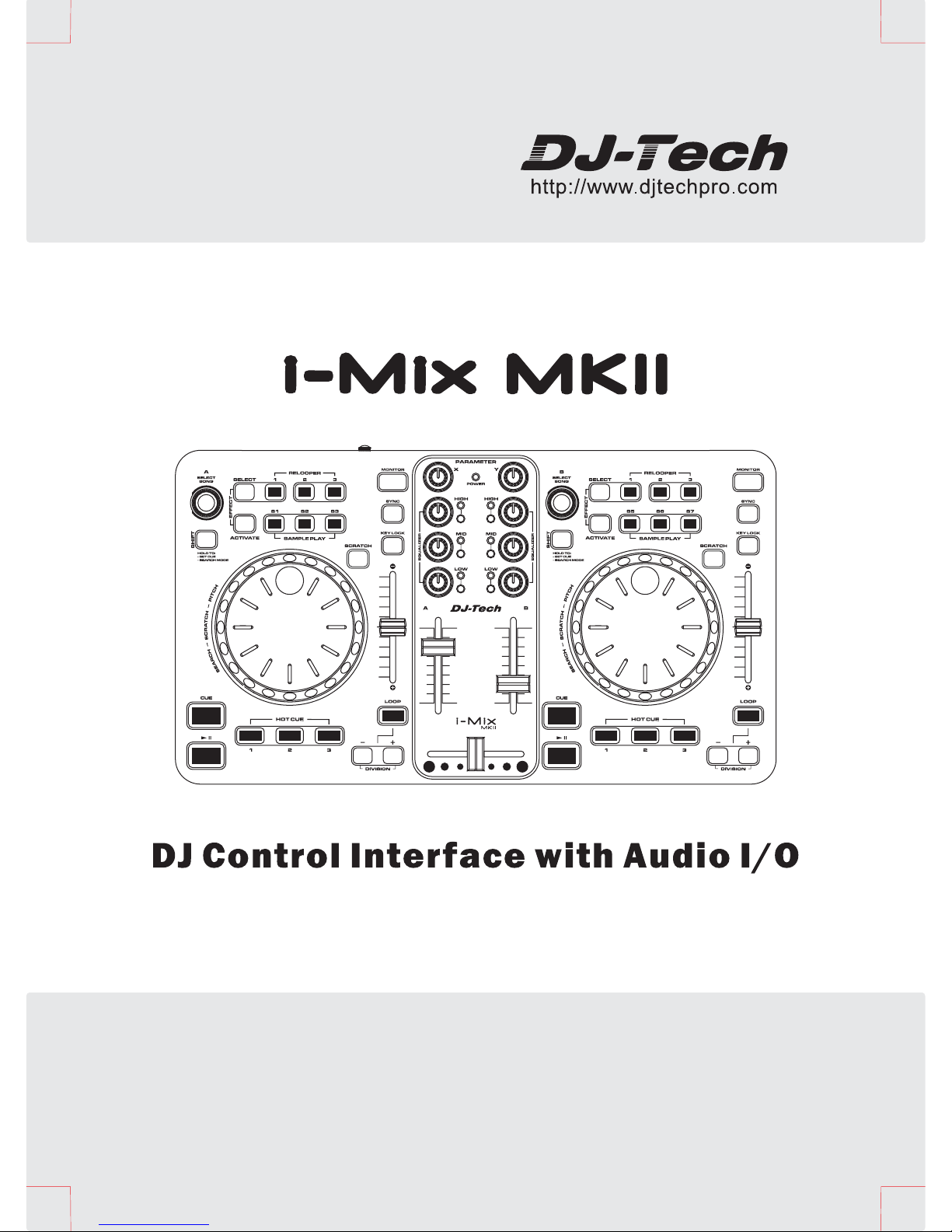
DJ-Tech i-Mix MKII User Manual
USER MANUAL
MANUEL D’UTILISATION
BENUTZERHANDBUCH
GEBRUIKSAANWIJZING
MANUAL DE INSTRUCCIONES
MANUALE DI ISTRUZIONI
(English)
(Français)
(Deutsch)
(Nederlands)
(Español)
(Italiano)
01~06
07~12
13~18
19~24
25~30
31~36

ESPAÑOL
ITALIANO
NEDERLANDS
ENGLISH
FRANÇAIS
DEUTSCH
1. Read these instructions.
2. Keep these instructions.
3. Heed all warnings.
4. Follow all instructions.
5. Do not use the apparatus near water.
6. Clean only with dry cloth.
7. Do not block any ventilation openings. Install in accordance with the manufacturer’s instructions.
8. Do not install near any heat sources such as radiators, heat registers, stoves, or other apparatus
(including amplifiers) that produce heat.
9. Do not defeat the safety purpose of the polarized or grounding-type plug. A polarized plug has two
blades with one wider than the other. A grounding- type plug h as two blad es and a thi rd grounding
prong. The wide blade or the third prong is provided for your saf ety. If the provid ed plug does not fit into
your outlet, consult an electrician for replacement of the obsolete outlet.
10. Protect the power cord from being walked on or pinched particularly at plugs, convenience receptacles,
and the point where they exit from the apparatus.
11. Only use attachments/ accessories specified by the manufacturer.
12. Us e on ly w i t h a c art , st a nd, t rip o d, b rac k et o r table specified by the manufacturer, or
sold with the apparatus. When a cart is used, use caution when moving the
cart/apparatus combination to avoid injury from tip-over.
13. Unplug this apparatus during lighting storms or when unused for lo ng periods of time.
14. Refer all servicing to qualified service personnel. Servicing is required when the apparatus has been
damaged in any way, such as power-supply cord or plug is damaged, liquid has been spilled or
objects have fallen into the apparatus, the apparatus has been exposed to rain or moisture, does not
operate normally, or has been dropped.
15. The main plug is used as the disconnect device, the disconnect device shall be readily operable.
WARNING
To reduce the risk of fire or electric shock, do not expose this apparatus to rain or moisture. The
apparatus shall not be exposed to dripping or splashing and that no objects filled with liquids, such
as vases, shall be placed on the apparatus.
CAUTION: To reduce the risk of electric shock, do not remove any
cover. No user-serviceable parts inside. Refer servicing to qualified
service personnel only.
The lightning flash with arrowhead symbol within the equilateral triangle is intended to alert
the use to the presence of un-insulated “dangerous voltage” within the product’s enclosure
that may be of sufficient magnitude to constitute a risk of electric shock.
CAUTION
To prevent electric shock, do not use this polarized plug with an extension cord, receptacle or other
outlet unless the blades can be fully inserted to prevent blade exposure.
IMPORTANT SAFETY INSTRUCTIONS
DO NOT OPEN
RISK OF ELECTRIC SHOCK
The exclamation point within the equilateral triangle is intended to alert the user to the
presence of important operation and maintenance (servicing) instructions in the literature
accompanying this appliance.
1
ESPAÑOL
ITALIANONEDERLANDS
ENGLISH
FRANÇAIS
DEUTSCH
y Complete professional computer-DJ package with built-in Audio I/O
y High Definition Jog Wheels for Pitch Bending and Scratching.
y Adjustable Crossfader curve.
y Built-in 2-in 2-out Audio Interface
y Maximum 0.9V RMS Line Output
y 1 MIC, 2 Line Inputs, 2 Line Outputs and 1 Phone Output.
y Power LED for power and MIDI activities indication
y Powered by USB or external DC adaptor
y ASIO Audio Driver included for Windows XP/ Vista and Mac
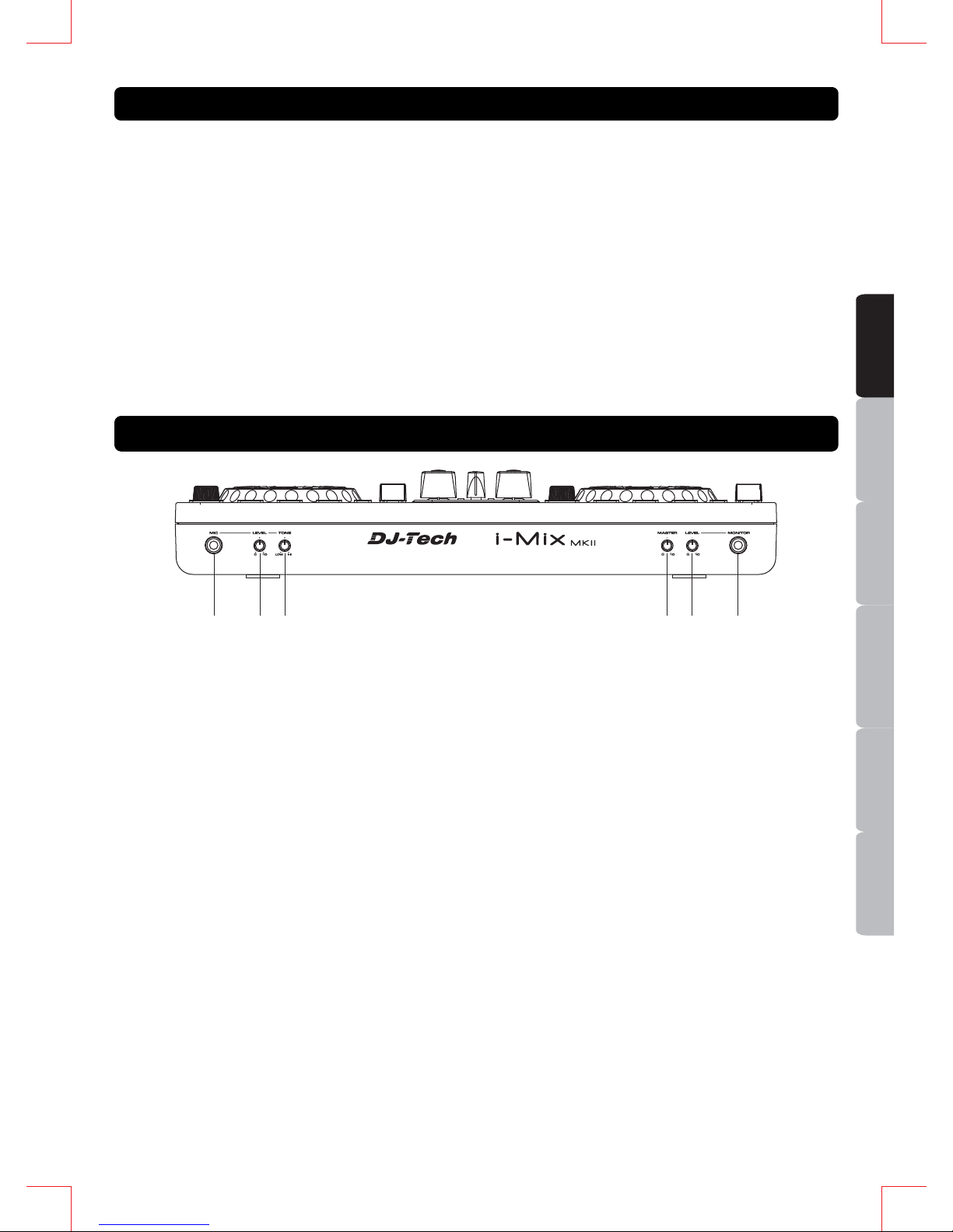
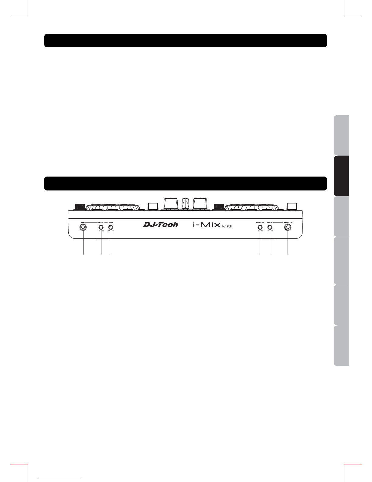
1. MIC INPUT JACK – This jack is used to connect a microphone to the device. Connect you
microphone via 1/4-inch (6.3mm) jack.
2. MIC LEVEL CONTROL – This knob is used to adjust the output volume of microphone. Turn the
knob in clockwise direction to increase the microphone volume.
3. MIC TONE CONTROL – This knob is used to adjust the tone of microphone betwee n Low and High.
In the center position, the tone control is middle.
4. MASTER LEVEL CONTROL – This knob is used to adjust the output volume of master. Turn the
knob in clockwise direction to increase the mast er volume.
5. MONITER LEVEL CONTROL – This knob is used to adjust the output volume of headphone. Turn
the knob in clockwise direction to increase the headphone volume.
Always be sure the MONITOR LEVEL is set to minimum before putting the headphones on.
6. MONITOR JACK - This jack is used to connect your headphones to the device allowing you to
monitor the cue source.
MAIN FEATURES
CONNECTION FRONT PANEL
1
23 4 5 6
2
ESPAÑOL
ITALIANO
NEDERLANDS
ENGLISH
FRANÇAIS
DEUTSCH
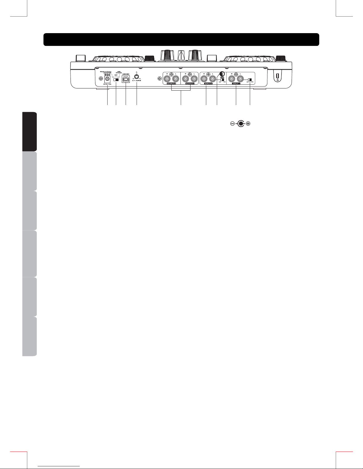
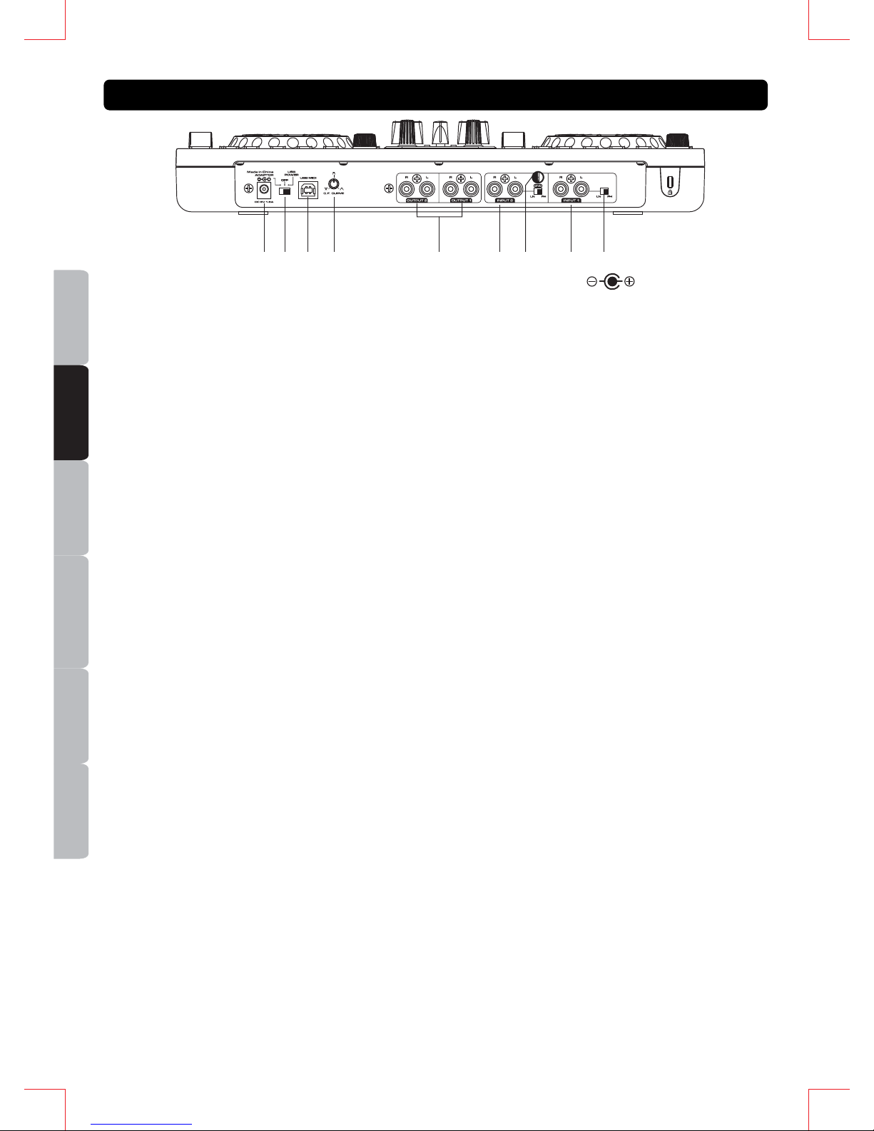
7. POWER CONNECTOR – Plug in power adapter here. DC adaptor can be used when the USB port
cannot provide enough power to the unit. Please use only a 6V DC adaptor.
8. POWER SWITCH (Adaptor / OFF/ USB power) – Set the switch to AC ADAPTOR when using
external DC adaptor (not included), set to USB BUS POWER when using power provided from the
computer via USB.
9. USB CONNECTOR – Used to connect a computer. It is recommended to use the USB Cable
included. Long or low quality USB cable may make the unit unstable.
10. C.F CURVE CONTROL – Adjusts the shape of the crossfader curve from a quick cut for scratching
or to a longer fade for mixing.
11. OUTPUT JACKS – These jacks send a left and right analog output signal from the USB audio
interface. Use the supplied RCA cables to connect these outputs to a main stereo system, like an
amplifier or active speakers.
12. INPUT JACKS – You can connect playback devices to these input jacks, such as CD players,
turntables, SD players or USB players. These connections are for the inputs to the USB audio interface.
When connecting phono output turntables, be sure the corresponding switch is in the “PH” position.
When connecting line level output devices, be sure the corresponding switch is in the “LN” position
13. GND (GROUND TERMINAL) – Be sure to connect turntable ground leads to the available ground
terminals. This will reduce the humming and popping noises associated with magnetic phono cartridges.
14. CHANNEL LINE LEVEL SELECTOR - These switches are used to select the line levels type of the
related Phono/Line jacks.
Always be sure main power is shut off before switching the Line Level Selector.
CONNECTION REAR PANEL
7
910
8 11 13
12
14
12
3
ESPAÑOL
ITALIANONEDERLANDS
ENGLISH
FRANÇAIS
DEUTSCH
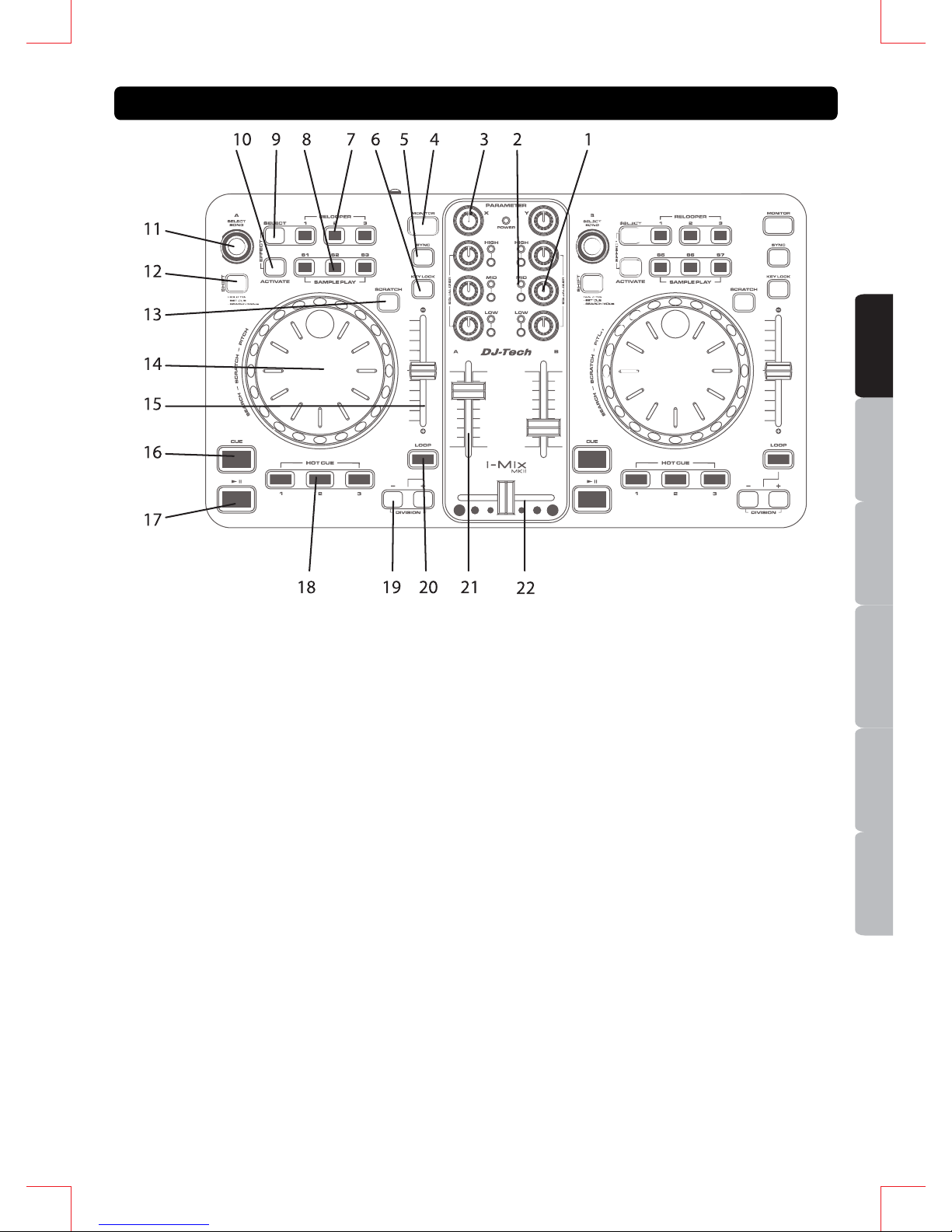
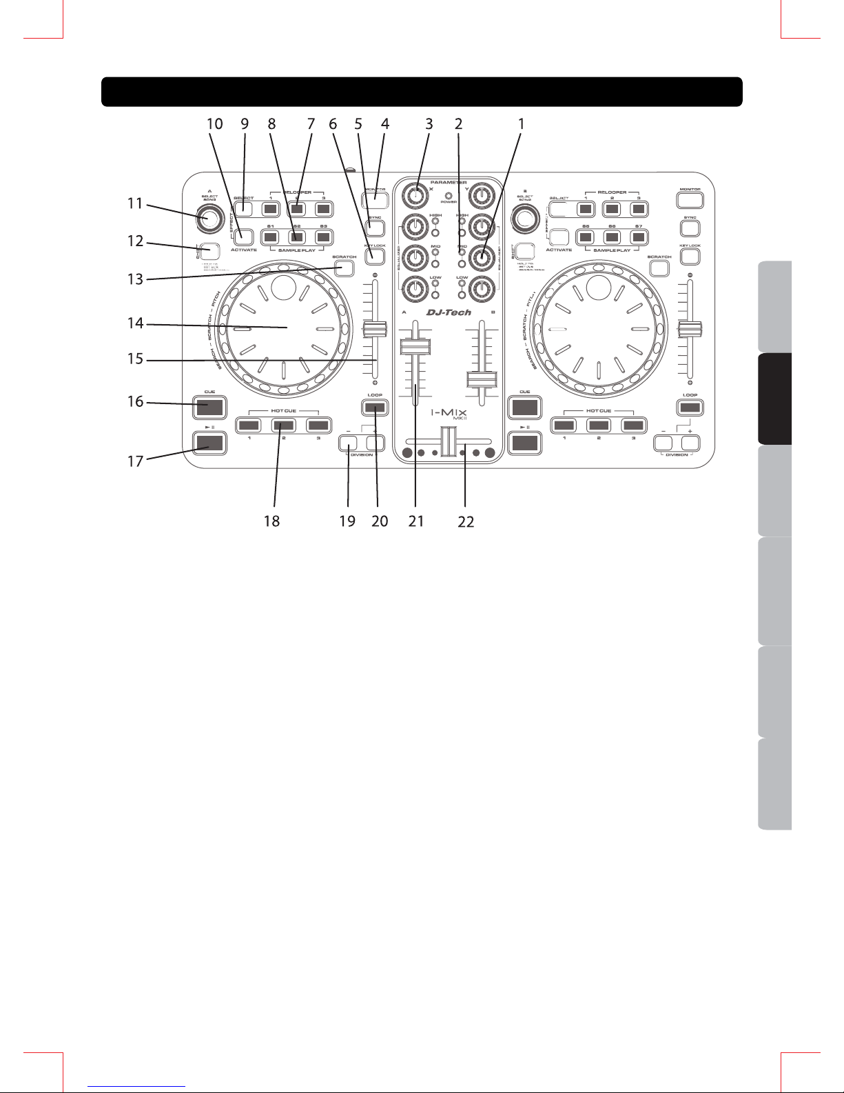
1. 3-BAND EQ KNOBS
2. EQ KILL BUTTONS
3. FX X-Y PARAMETER KNOBS – These 2
knobs will control the FX X-Y parameters for
both deck A and deck B at the same time.
4. MONITOR BUTTONS
5. SYNC BUTTONS
6. KEYLOCK BUTTONS
7. RELOOPER BUTTONS
8. SAMPLE PLAY BUTTONS – Toggle the
sample for Slot 1/ Slot 2/ Slot 3 (Deck A) or
Slot 5/ Slot 6/ Slot 7 (Deck B).
9. FX SELECT BUTTONS
10. FX ACTIVATE BUTTONS – Press to turn
ON/OFF the FX unit for Deck A or B. When
FX is turned on, the Blue (Deck A) or Amber
(Deck B) will show in the FX Control area in
Deckadance software.
11. SONG SELECT ENCODERS – Turn to select
song and press to load the song to Deck A or
B.
12. SHIFT BUTTONS – Press SHIFT together
with other buttons to enable the buttons
double features.
13. SCRATCH ON BUTTONS – Press to turn ON
/OFF the scratch function for the Jog Wheel.
14. JOG WHEELS – Used for Pitch, Scratch or
Search.
15. PITCH FADERS
16. CUE BUTTONS
17. PLAY/ PAUSE BUTTONS
18. HOT CUE BUTTONS
19. LOOP DIVISION BUTTONS
20. LOOP BUTTONS – Press and hold for Loop
function.
21. CHANNEL VOLUME FADERS
22. CROSSFADER
SHIFT FUNCTION
y SHIFT + SONG SELECT ENCODERS – Switch
between function windows in Deckadance.
y SHIFT + JOG WHEELS – Quick search in the
song.
y SHIFT + HOT CUE BUTTONS – Set Hot Cue.
y SHIFT + LOOP BUTTONS – Toggle Loop
function ON/OFF.
FUNCTIONS (DECKADANCE LE) TOP PANEL
4
ESPAÑOL
ITALIANO
NEDERLANDS
ENGLISH
FRANÇAIS
DEUTSCH
1. Install the DJ software from the software CD included.
2. Install the ASIO driver for i- Mix MKII from the So ftware CD “Drivers” folder. ( ASIO Driver also available
on http://www.djtechpro.com
)
3. You may need to power on/ off the i-Mix MKII when installing the driver.
4. Open the DJ software.
5. Start up the software to perform settings with the i-Mix MKII.
The software may not recognize the i-Mix MKII if it is connected to the computer after the software
has started.
6. Operations after the system recovering from power saving mode is not guaranteed.
Please power off and on again the unit when the system is recovered from power saving mode.
7. I-Mix MKII ca n be used with many other DJ software products that have a MIDI LEARN function. The i-Mix
MKII can control all software that has this function. i-Mix MKII can be used to control parameters of the
software. Please visit http://www.djtechpro.com
for supported DJ software like Traktor Pro. Some mapping
files are also available there.
The MIDI LEARN setting for any software is different; please refer to any software's manual for
further instructions.
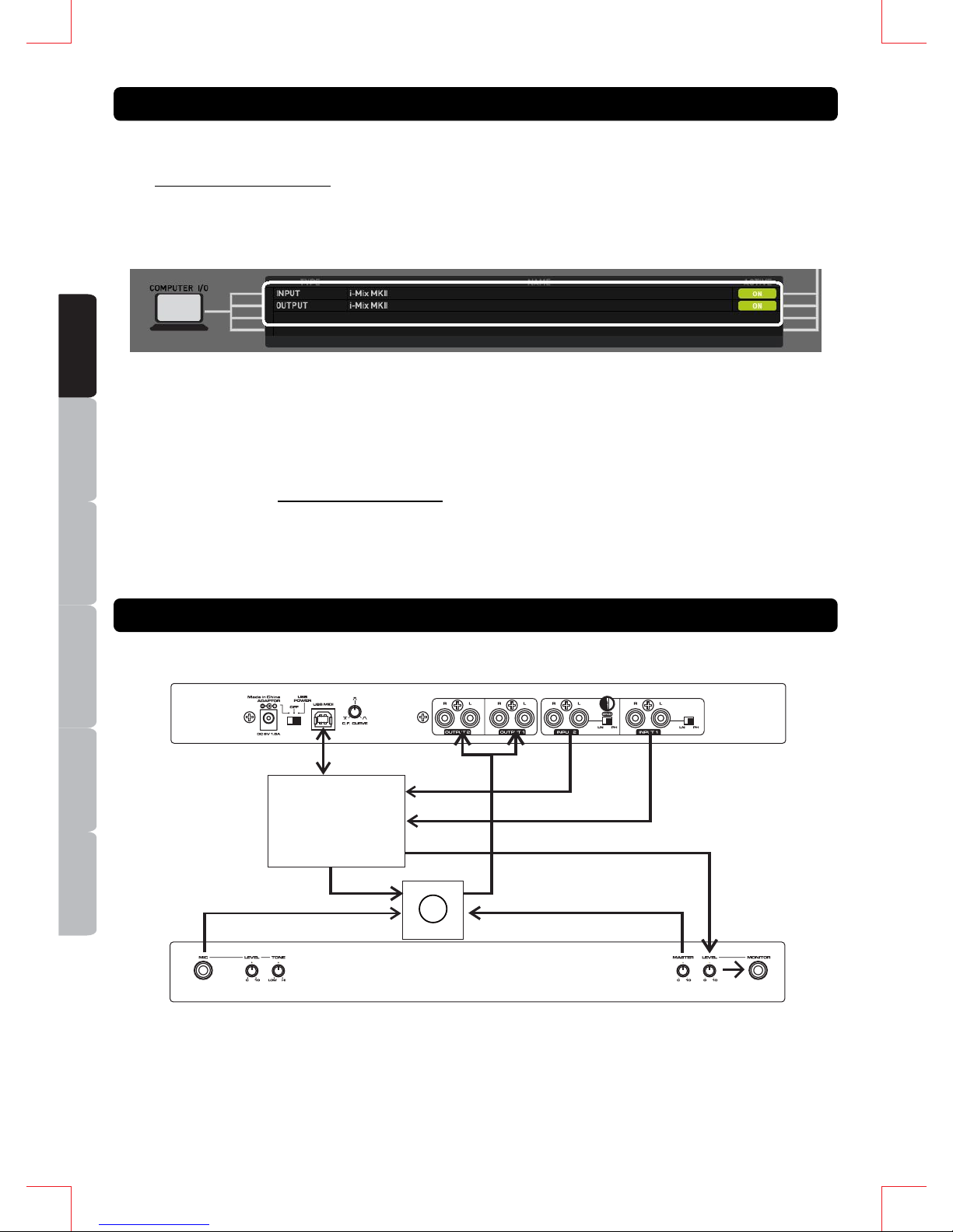
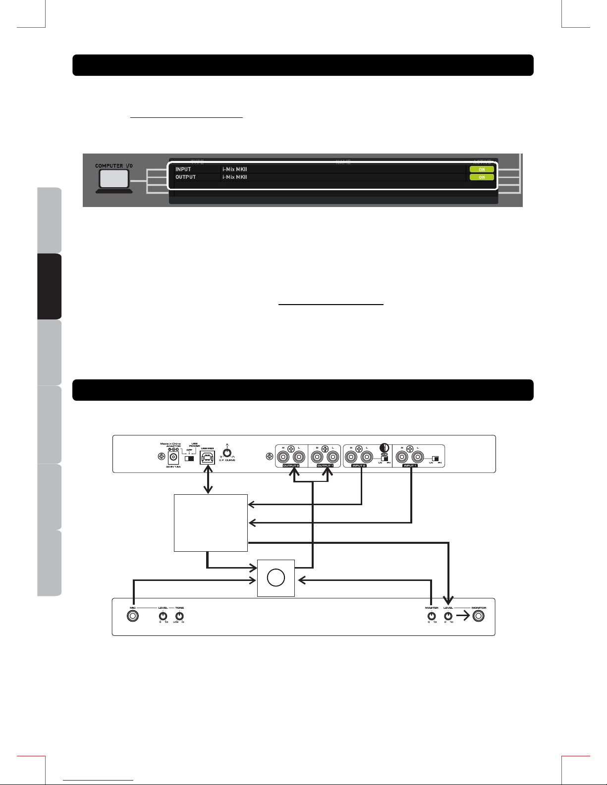
Block Diagram for the USB Audio Configuration
1. The audio interface of the unit is only an USB Audio Soundcard, while the faders and knobs controls
are for MIDI only. The unit cannot work as a mixer without the use of computer software.
2. Audio of Output 1 and Output 2 at the rear panel are the same, they are from USB Audio Output 1
plus the Microphone signal.
OPERATIONS
AUDIO I/O CONFIGURATION
2-in 2-out
USB Audio
Soundcard
Volume Control
Audio Out 1
Mic In
Audio Out 2
Audio In 2
Audio In 1
Audio Output to Rear Panel
FRONT PANEL
REAR PANEL
∑
USB
5
6
ESPAÑOL
ITALIANONEDERLANDS
ENGLISH
FRANÇAIS
DEUTSCH
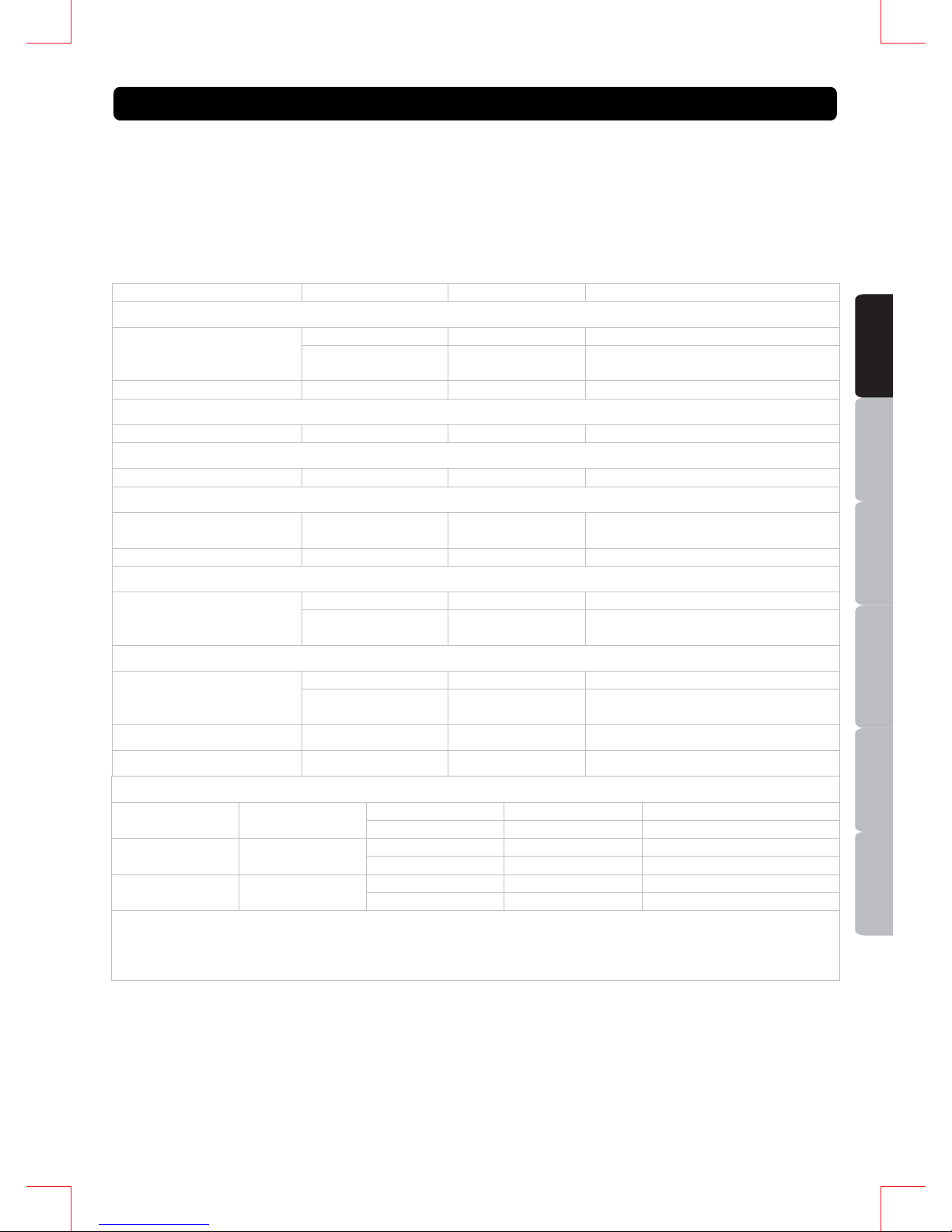
PRODUCT DJ Control Interface with Audio I/O
POWER SOURCE DC6V, 1.5A
POWER CONSUMPTION 9 WATTS
DIMENSIONS 360mm (W) X 203mm (D) X 64.5mm (H)
WEIGHT 1.56kg
AUDIO CHARACTERISTICS (LOAD: LINE=100Kohm, PHONES=32ohm, ALL VR MAXIMUM, TEST
SIGNAL: MP3,128Kbps)
ITEM TYPICAL LIMIT CONDITION
x OUTPUT LEVEL
0.9V +/-0.5d B 0.9V +/-1dB 1KHz, 0dB (TCD-782 TRK.2) LINE OUTPUT 1&2
0.9V +/-1dB 0.9V +/-1.5dB MIC 1KHz, -36dB
(LEVEL,TONE MAXIMUM)
PHONES 0.4V + /- 0 . 5d B 0. 4 V + / - 1d B 1KHz,-20dB (TCD-782 TRK.16)
x CHANNEL BALANCE
LINE OUTPUT 1&2 WIT HIN 0 .5dB WIT HIN 1dB 1KHz, 0dB (TCD-782 TRK.2)
x L/R CHANNEL SEPARATION(*2)
LINE OUTPUT 1&2 80dB 76dB 1KH z , 0 d B ( T C D - 7 8 2 TR K . 9 & 1 1 )
x THD+N(*1)
LINE OUTPUT 1&2 0.02% 0.05% 1KHz, 0dB (TCD-782 TRK.2/
OUTPUT 0.9V +0/-1B)
PHONES 0.03% 0.06% 1KHz, 0dB (1V OUTPUT)
x S/N RATIO(*2)
82dB 78dB 1KHz, 0dB (TCD-782 TRK.2 & 8) LINE OUTPUT 1&2
65dB 60dB MIC 1KHz, -50dB
(LEVEL,TONE MAXIMUM)
x FREQUENCY RESPONSE
17Hz-16KHz +/-0.5dB 17Hz-16KHz +/-1dB (TCD-781 TRK.1,4 & 16) LINE OUTPUT 1&2
20Hz-20KHz +/-1.5dB 20Hz-20KHz +/-3dB MIC 1KHz, -50dB
(LEVEL,TONE MAXIMUM)
x PHONES MAX. OUTPUT 1.5V 1.4V 1KHz, 0dB, THD=1%
x MIC TONE -14dB +/-2dB -14dB +/-3dB 10KHz -50dB (TONE VR MAX TO MIN)
x RECORD/PLAY SECTION (MASTER VR MAXIMUM)
0.8V +/-1dB 0.8V +/-1.5dB LINE IN 1KHz +6dBV(2V) INPUT LEVEL LINE 1&2 OUTPUT
0.7V +/-1dB 0.7V +/-1.5dB PHONO IN 1KHz -30dBV
20Hz-20KHz +0/-1dB 20Hz-20KHz +0/-3dB LINE IN 1KHz +6dBV(2V) FREQUENCY
RESPONSE
LINE 1&2 OUTPUT
20Hz-20KHz +1/-2dB 20Hz-20KHz +2/-3dB PHONO I N 1KHz -5 0dB(RI AA)
80dB 76dB LINE IN 1KHz +6dBV(2V) S/N RATIO(* 2) LINE 1&2 OUTPUT
72dB 66dB PHONO IN 1KHz -30dBV
NOTES:
1: WITH 20KHz LOW PASS FILTER.
2: WITH 20KHz LOW PASS FILTER, "IHF-A" WEIGHTED.
3. ALL TEST CONDITION WITH EXTERNAL POWER SUPPLY UNIT
SPECIFICATION
ESPAÑOL
ITALIANO
NEDERLANDS
ENGLISH
FRANÇAIS
DEUTSCH
1. Lisez les instructions suivantes.
2. Conservez ces instructions.
3. Respectez tous les avertissements.
4. Suivez toutes les instructions.
5. N’utilisez pas l’appareil près d’une source d’eau.
6. Nettoyez-le uniquement avec un chiffon doux et sec.
7. N’obstruez pas les ouvertures de ventilation. Installez l’appareil conformément aux instructions du
fabricant.
8. N’installez pas l'appareil près de sources de chaleur telles qu’un radiateur, une bouche à air chaud,
un amplificateur ou tout autre appareil qui produit de la chaleur.
9. Ne contournez pas le dispositif de sécurité de la fiche polarisée ou avec mise à la terre. Toute fiche
polarisée dispose de deux lames dont une est plus grande que l’autre. Toute fiche avec mise à la
terre dispose de trois lames dont une pour la mise à la terre. La lame la plus large et la lame de
mise à la terre assurent votre sécurité. Si la fiche ne correspond pas à votre prise secteur,
consultez un électricien pour remplacer votre prise secteur o bsolète.
10. Placez le cordon d’alimentation de manière à ne pas le piétiner ou l'écraser. Faites particulièrement
attention à la fiche et à l’endroit où le cordon sort de l’appareil.
11. Utilisez exclusivement des attaches/accessoires recommandé(e)s par le fabricant.
12. Ne placez pas ce produit sur une surface instable, cela pourrait causer des blessures
corporelles ou des dommages sérieux à l’appareil. Si vous utilisez un chariot, déplacez
l’appareil avec prudence afin d’éviter de le renverser et de blesser quelqu’un.
13. Débranchez l’appareil en cas d’orage ou de non-utilisation prolongée.
14. Confiez toutes les opérations d'entretien à un technicien qualifié. Une réparation est nécessaire
lorsque l’appareil a été endommagé de quelque manière que ce soit : fiche ou câble d’alimentation
abîmé(e), introduction de liquides ou d’objets dans l’appareil, exposition à la pluie ou à l’humidité,
dysfonctionnement, chute.
15. La fiche permet de débrancher l’appareil et doit rester facilement accessible.
AVERTISSEMENT
Pour réduire le risque d'incendie ou de choc électrique, n’exposez pas cet appareil à la pluie ou à
l'humidité. Ne placez aucun récipient rempli de liquide, tel qu’un vase, à proximité de celui-ci.
ATTENTION : Ne démontez pas l’appareil afin de prévenir tout
risque de choc électrique. Aucune pièce interne ne peut être
réparée par l’utilisateur. Confiez toutes les opérations d'entretien à
un technicien qualifié.
Le symbole de l'éclair terminé par une flèche situé à l'intérieur d'un triangle équilatéral
avertit l'utilisateur de la présence de tension dangereuse non isolée dans l'appareil, dont
l’amplitude peut constituer un risque de choc électrique.
Le symbole du point d’exclamation dans un triangle équilatéral vise à avertir l’utilisateur de
la présence, dans la documentation accompagnant cet appareil, d’importantes instructions
de fonctionnement et d’entretien.
ATTENTION
Pour prévenir tout risque de choc électrique, veillez à ce que les bornes de la fiche d’alimentation
soient insérées complètement, de manière à ne pas être exposées.
INFORMATION DE SECURITE IMPORTANTE
DO NOT OPEN
RISK OF ELECTRIC SHOCK
7
ESPAÑOL
ITALIANONEDERLANDS
ENGLISH
FRANÇAIS
DEUTSCH
y Package DJ professionnel et complet pour ordinateur avec ent rée/sortie audio intégrée.
y Molettes jog haute précision pour le pitch bend et le scratch.
y Courbe du crossfader ajustable
y Interface Audio 2 entrées 2 sorties
y Sortie Line Maximum 0.9V RMS
y 1 MIC, 2 Entrées Line, 2 Sorties Line et 1 Sortie Phone
y LED d’alimentation et indication d’activité MIDI
y Alimenté par USB ou par adaptateur secteur externe
y Driver Audio ASIO inclus pour Windows XP/ Vista et Mac
1. ENTRÉE JACK MICRO – Cette entrée est utilisée pour connecter un microphone. Connecter votre
micro via un câble jack 6.3mm.
2. CONTROLE DU NIVEAU DU MICRO – Ce bouton est utilisé pour ajuster la sortie du volume du
microphone. Tourner le bouton dans le sens d’une aiguille d’une montre pour augmenter le volume.
3. CONTROLE DE LA TONALITE DU MICRO – Ce bouton est utilisé pour ajuster la tonalité du
microphone entre grave et aigue.
4. CONTROLE DU NIVEAU DU VOLUME PRINCIPAL – Ce bouton est utilisé pour ajuster la so rtie du
volume principal. Tourner le bouton dans le sens d’une aiguille d’une montre pour augmenter le
volume master.
5. BOUTON VOLUME PRE ECOUTE – Ce bouton est utilisé pour ajuster le volume du casque.
Tourner le bouton dans le sens d’une aiguille d’une montre pour augmenter le volume.
Toujours vérifier que MONITOR LEVEL est régler sur le minimum avant de mettre le casque.
6. PRE ECOUTE – Ce jack est utilisé pour connecter votre casque sur l’appareil.
CARACTERISTIQUES PRINCIPALES
CONNECTION PANNEAU AVANT
1
23 4 5 6
8
ESPAÑOL
ITALIANO
NEDERLANDS
ENGLISH
FRANÇAIS
DEUTSCH
7. CONNECTEUR D’ALIMENTATION – Brancher l’adaptateur secteur ici.
8. BOUTON D’ALIMENTATION (Adaptateur / OFF/ USB power) – Régler le bouton en position AC
ADAPTOR lorsque vous utilisez l’adaptateur sec teur, régler le bouton en pos ition USB POWER lorsque
l’alimentation provient de l’ordi nateur via USB.
9. ENTRÉE USB – Utilisez l’entrée USB pour connecter à l’ordinateur.
10. CONTROLE C.F CURVE – Permet de régler la forme de la courbe du crossfader rapidement, pour
scratcher ou pour mixer.
11. SORTIE JACKS – Envoie des signaux de sorties gauches et droites analogues de l’interface audio
USB. Utiliser les câbles RCA pour connecter ces sorties à un système stéréo principal tel un ampli
ou des enceintes actives.
12. ENTREE JACKS – Vous pouvez connecter un lecteur à cet entrée jacks, tells que lecteur CD,
tourne disque, lecteurs SD ou lecteur USB.
Lorsque vous connectez la sortie PHONO du tourne disque, vérifier que l’interrupteur est sur la
position “PH”.
Lorsque vous connectez la sortie line, vérifiez que l’interrupteur est sur la position “LN”.
13. MASSE (GND) – vérifiez que vous avez bien connecté les masses des l’appareil.
14. SELECTEUR DE CANAL LINE – ce sélecteur est utilisé pour sélectionner le type d’entrée
Phono/Line.
Toujours vous assurez que l’alimentation est éteinte avant d’utiliser le sélecteur.
CONNECTION PANNEAU ARRIERE
7
910
8 11 13
12
14
12
9
ESPAÑOL
ITALIANONEDERLANDS
ENGLISH
FRANÇAIS
DEUTSCH
1. Boutons de réglage de l’équaliseur 3 bandes
2. Boutons KILL pour l’équaliseur
3. Boutons de réglages des paramètres X-Y –
Ces deux boutons vous permettent de contrôler
les paramètres X et Y des effets tant pour le
deck A que pour le deck B.
4. Boutons MONITOR
5. Boutons SYNC
6. Boutons KEYLOCK
7. Boutons RELOOPER
8. Touches SAMPLE PLAY – Sélection d’un
sample : Slot 1 / Slot 2 / Slot 3 (Deck A) ou
Slot 5 / Slot 6 / Slot 7 (Deck B)
9. Boutons SELECT – Sélection d’un effet
10. Boutons ACTIVATE – Activation/désactivation
des effets sur le deck A ou B. Lorsque les
effets sont activés, la zone de contrôle des
effets sur le logiciel Deckadance devient
bleue pour le deck A et ambre pour le deck B.
11. Boutons SELECT SONG – Utilisez ces boutons
pour sélectionner un titre et le charger sur le
deck A ou B.
12. Boutons SHIFT – Pour accéder à la deuxième
fonction des boutons double fonction,
appuyez simultanément sur ce bouton et sur
SHIFT.
13. Boutons SCRATCH – Activation/désactivation
de la fonction scratch de la molette jog.
14. Molettes JOG – Utilisez les molettes jog pour
le réglage du Pitch, pour le scratch ou pour
effectuer une recherche.
15. Potentiomètre de réglage du PITCH FADER
16. Boutons CUE
17. Boutons / (lecture/pause)
18. Boutons HOT CUE
19. Boutons DIVISION
20. Boutons LOOP– Appuyez longuement sur
cette touche pour lancer le loop.
21. Potentiomètres de réglage du volume du
canal
22. Crossfader
SHIFT FUNCTION
y SHIFT + SONG SELECT ENCODERS –
Switch between function windows in
Deckadance
y SHIFT + JOG WHEELS – Quick search in the
song
y SHIFT + HOT CUE BUTTONS – Set Hot Cue
y SHIFT + LOOP BUTTONS – Toggle Loop
function ON/OFF
FONCTIONS (DECKADANCE LE) PANNEAU DU DESSUS
10
ESPAÑOL
ITALIANO
NEDERLANDS
ENGLISH
FRANÇAIS
DEUTSCH
1. Installer le software norm
alement.
2. Installer le driver ASIO pour i-Mix MKII du répertoire “Drivers” du CD. (le Driver ASIO est disponible
sur le site http://www.djtechpro.com
)
3. Vous avez besoin d’allumer/d’éteindre le i-Mix MKII lorsque vous installer le driver.
4. Ouvrir le DJ software. i-Mix MKII.
Le software pourrait ne pas être reconnu par le i-Mix MKII s’il est connecté sur l’ordinateur après
que le software ait démarré.
5. Les opérations de récupération après un mode d’économie d’énergie n’est pas garantie.
Veuillez éteindre et rallumer l’appareil lorsque l’appareil est en mode d’économie d’énergie.
6. I-Mix MKII peut être utilise avec pleins d’autres DJ software qui ont la fonction MIDI LEARN. Le i-Mix MKII
peut contrôler tous les softwares qui ont cette fonction. i-Mix MKII peut être utilisé pour contrôler les
paramètres du software. Veuillez visiter le site http://www.djtechpro.com
afin de soutenir les logiciels DJ tels
que Traktor Pro. D’autres fichiers sont également disponibles sur le site.
Le paramétrage du MIDI LEARN pour chaque software est différent; Veuillez vous référer à
chaque manuel de l’utilisateur pour plus amples informations.
Diagramme pour la configuration USB Audio
1. L’interface audio de l’appareil est uniquement une carte Son USB, tandis que le fader et les boutons
de contrôles sont pour MIDI uniquement.
2. L’appareil ne peut pas fonctionner comme une table de mixage sans l’utilisation du logiciel de
l’ordinateur.
3. Les sorties Audio 1 et 2 qui sont à l’arrière de l’appareil sont les même.
OPERATIONS
CONFIGURATION AUDIO I/O
Contrôle du Volume
Sortie Audio 1
Entrée Mic
Sortie Audio 2
Entrée Audio 2
Entrée Audio 1
Sortie Audio à l'arrière
PANNEAU AVANT
PANNEAU ARRIERE
∑
USB
Carte son USB
2-entrées 2
sorties
11
 Loading...