

USER MANUAL
MANUEL D’UTILISATION
(English)
(Français)
02~06
07~11
DX3000USB
Professional 7-Channel USB DJ Mixer
2
IMPORTANT SAFETY INSTRUCTIONS
1. Read these instructions – All the safety and operating instructions should be read before
this product is operated.
2. Keep these instructions – The safety and operating instructions should be retained for
future reference.
3. Heed all warnings – All warnings on the appliance and in the operating instructions
should be adhered to.
4. Follow all instructions – All operating and use instructions should be followed.
5. Do not use this apparatus near water – The appliance should not be used near water or moisture – for
example, in a wet basement or near a swimming pool, and the like.
6. Clean only with dry cloth.
7. Do not block any ventilation openings. Install in accordance with the manufacture’s instructions.
8. Do not install near any heat sources such as radiators, heat registers, stoves, or other apparatus
(including amplifiers) that produce heat.
9. Do not defeat the safety purpose of the polarized or grounding plug. A polarized plug has two blades with
one wider than the other. A grounding plug has two blades and a third grounding prong.
The wide blade or the third prong is provided for your safety. If the provided plug does not fit into your
outlet, consult an electrician for replacement of the obsolete outlet.
10. Protect the power cord from being walked on or pinched particularly at the plugs, convenience
receptacles, and at the point where they exit from the apparatus.
11. Only use attachments/accessories specified by the manufacturer.
12. Use only with the cart, stand, tripod, bracket, or table specified by the manufacturer, or sold with the
apparatus. When a cart or rack is used, use caution when moving the cart/apparatus combination to
avoid injury from tip-over.
13. Unplug the apparatus during lightning storms or when unused for long periods of time.
14. Refer all servicing to qualified personnel. Servicing is required when the apparatus has been damaged
in any way, such as power supply cord or plug is damaged, liquid has been spilled or objects have fallen
into the apparatus has been exposed to rain or moisture, does not operate normally, or has been
dropped.
15. CAUTION: These servicing instructions are for use by qualified service personnel only. To reduce the
risk of electric shock, do not perform any servicing other than that contained in the operating instructions
unless you are qualified to do so.
16. Do not install this equipment in a confined or building-in space such as a book case or similar unit, and
remain a well ventilation conditions at open site. The ventilation should not be impeded by covering the
ventilation openings with items such as newspaper, table-cloths, curtains etc.
17. WARNING : To reduce the risk of fire or electric shock, do not expose this apparatus to rain or moisture.
The apparatus shall not be exposed to dripping or splashing and that objects filled with liquids, such as
vases, shall not be placed on apparatus.
18. WARNING: The mains plug or appliance coupler is used as disconnect device, the disconnect device
shall remain readily operable.
19. This lightning flash with arrowhead symbol within an equilateral triangle is intended to alert the user to
the presence of non-insulated “dangerous voltage” within the product’s enclosure that may be of
sufficient magnitude to constitute a risk of electric shock.
20. Warning: To reduce the risk of electric shock, do not remove cover (or back) as there are no
user-serviceable parts inside. Refer servicing to qualified personnel.
21. The exclamation point within an equilateral triangle is intended to alert the user to the presence of
important operating and maintenance instructions in the literature accompanying the appliance.
22.
Protective earthing terminal. The apparatus should be connected to a mains socket outlet with a
protective earthing connection.
SAFETY INSTRUCTIONS
3
FEATURES
- Professional, 7-channel, ultra-low noise DJ mixer
- 45-mm crossfader with adjustable curve
- Built-in USB interface for recording and playback of any digital music file from computer
- 5 dual stereo inputs plus 2 mono mic/line channels with mic preamps, gain control
- LED level meter on all stereo channels and master output
- Long-wearing 100-mm faders and sealed rotary controls on all input channels.
- Headphones output with Level and Balance (PFL/ Main) controls, switchable split mode
- Main Out, Sub Out, 2 Zone outputs for second room/ area
- Golden terminals
- DJ Software: Traktor 3 LE & Deckadance LE included
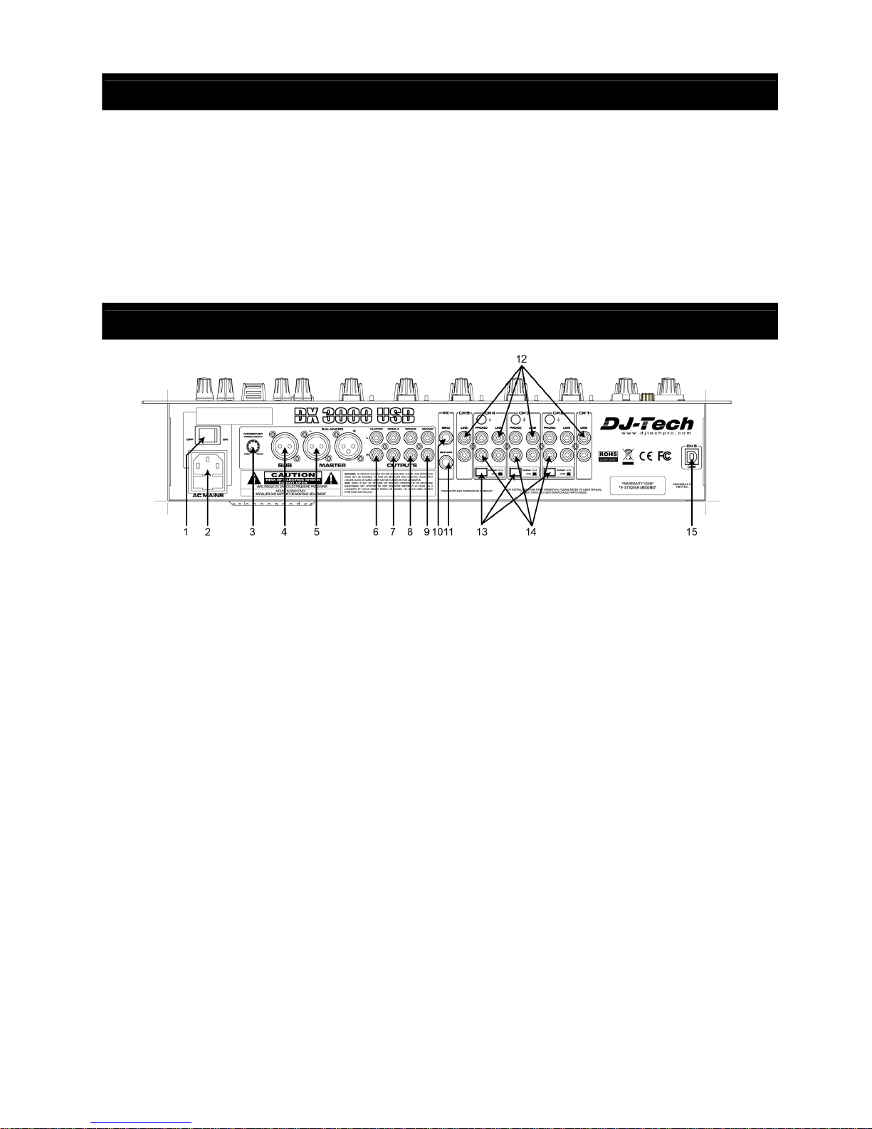
PART NAME AND FUNCTIONS (Rear Panel)
1. Power switch. Switches the unit on and off. Make sure to switch the unit off when not in use.
2. AC inlet and fuse holder. Use the supplied AC cord to connect the unit to AC mains. Make sure
voltage and frequency stated on the unit comply with your local AC supply. The fuse can be
accessed by the small drawer at the AC inlet. To change the fuse, unplug the AC cord first, pull out
the fuse drawer and replace the fuse ONLY with a fuse of SAME voltage and rating. If the fuse
blows again after replacement, hand over the unit to qualified service personnel.
3. Crossover Frequency Knob. This knob is used to adjust the crossover frequency of the low pass
filter. (Low pass filter variable from 30Hz to 200Hz)
4. SUB bass output. This can be used to drive a very low frequency sound system in a studio or club
to provide added bottom end.
5. Main stereo output. This is a balanced stereo output carrying the main output signal controlled by
(27).
6. Main stereo output. This is an unbalanced out carrying the same signal as output (5).
7. Zone A (Booth) stereo output. This is an unbalanced output carrying the booth signal controlled by
(30). This output can be used for a 2
nd
zone which needs independent volume control, such as the
DJ booth or the seating area of a club.
8. Zone B (Booth) stereo output. This is an unbalanced output carrying the booth signal controlled by
(31).
9. Record output. This is an unbalanced stereo output carrying the same signal as the main output
(5), but not influenced by the main volume control (27). This is normally used for recording the
output to an external tape, CD or memory device.
10. FX Send output.
11. FX Return input.
12. Line inputs. These RCA connectors provide inputs for line-level signals to the assigned channels.
13. Sensitivity/Equalization selectors for inputs (14).
14. Phono Inputs. Depending on the position of the selector switches (13), these RCA connectors
provide the following inputs: (A) Position “PHONO”: input for phono-level signals to the assigned
channels, featuring the necessary RIAA equalization. (B) Position “LINE”: input for line-level
signals to the assigned channels. Note that if the Phono inputs are not used and the sensitivity is
4
switched to “PHONO”, the inputs shall be terminated with the supplied termination plugs (as
factory-inserted at delivery).
15. USB connector. Connect to a computer with the included USB cable to use as an audio interface.
Audio from computer will be sent to CH5 of the mixer. The audio signal from Record output (9) will
be sent to computer.
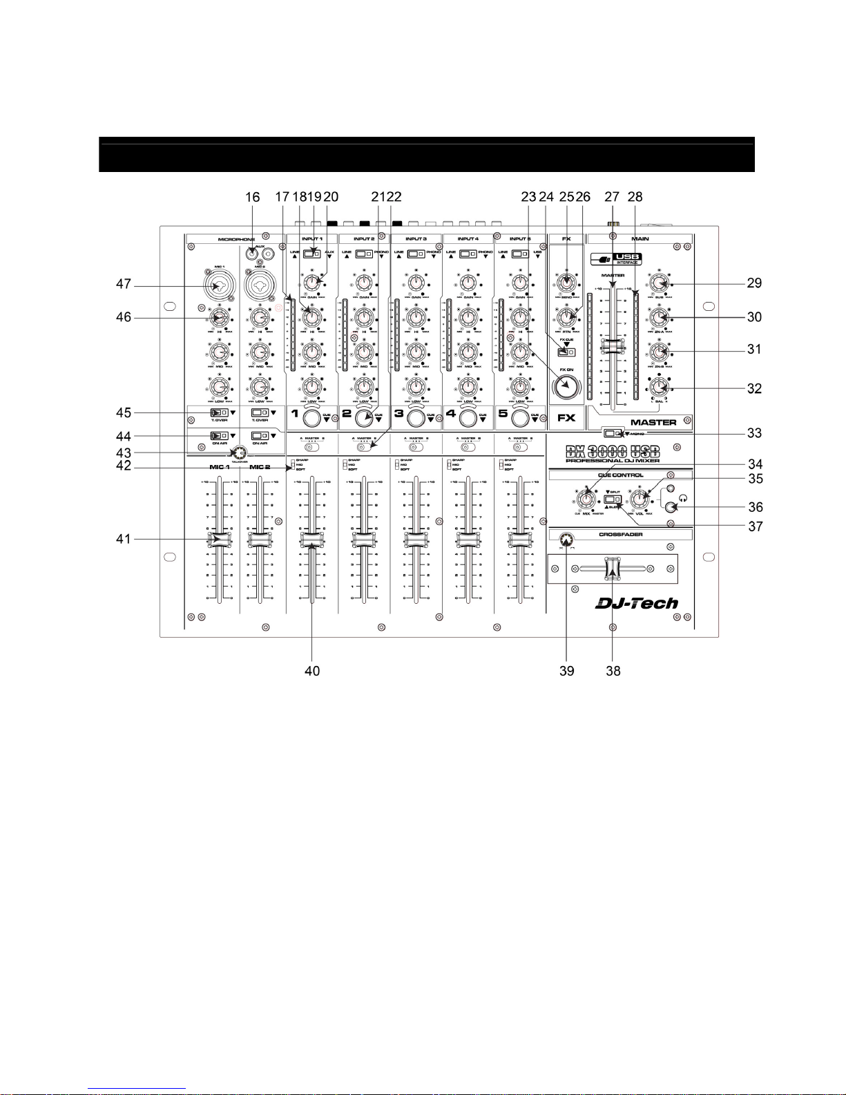
PART NAME AND FUNCTIONS (Top Panel)
16. AUX input. The RCA AUX input for Channel 1.
17. Input level meter for stereo channels. Display the current input level after the Gain control (20) and
allows visual adjustment to the same level for all inputs.
18. Equalizer for stereo channels. Allows the adjustment of the tonal balance for each of the stereo
inputs in three music-specific frequency bands with an adjustment range of -26/+12dB, thus
providing a virtual “kill” function for each frequency band if set to extreme attenuation.
19. Input selector for stereo channels. Switches between the inputs as indicated on the front panel. A
LED indicates the pressed position.
20. Gain control for stereo channels. Allows adjustment of the input sensitivity to compensate for
different source volumes.
21. PFL switch for stereo channels. Assigns the respective channel to the headphone bus for
pre-fader-listening (PFL). A LED indicates the pressed position.
22. Crossfader assignment switch. This switch determines whether the respective channel’s signal is
sent to the left side (A) of the crossfader, the right side (B) of the crossfader or directly to the
master output (MASTER).
23. Effects on/off switch. Activates the effect from FX Return (11). Once the effect is active, this switch
is backlit.

5
24. Effects PFL switch. Allows to pre-listen the generated effect without the effect being activated by
(23).
25. FX send control.
26. FX return control
27. Main level control. Determines the main output level present at outputs (5) and (6).
28. Main level meter. Displays the output level at outputs (5) and (6).
29. SUB level control. Control the output level of SUB out (3).
30. Zone A level control. Determines the booth output level present at output (7).
31. Zone B level control. Determines the booth output level present at output (8).
32. Balance control for main output. Determines the ration of left/right output levels at outputs (5) and
(6).
33. Mono/Stereo switch for main output. Allows the main output to be switched to mono operation. A
LED indicates the pressed position.
34. PFL Mix control. If the PFL mode (37) is set to “BLEND”, the headphone signal can be a mix of the
main output and the input(s) assigned to the PFL bus by means of switches (21). This control
determines the mix ration between the main and the PFL signal.
35. PFL level. Determines the signal volume at the headphone output (36). Always set this control to
minimum before putting on headphones, as sudden high-volume impact may damage your ears.
36. Headphones output. Provided, ¼” (6.35mm) TRS jack for headphones connection. Turn the PFL
level (35) down before plugging in any headphones.
37. PFL Mode switch. This control offers two pre-listening modes: (A) Split. In this mode, the main
signal appears on one earcup of the headphones, the PFL signal on the other earcup. (B) Blend.
In this mode, main and PFL signal are mixed with adjustable ration by means of control (34). A
LED indicates the pressed position.
38. Crossfader. A high-grade dual rail 45mm fader determines the mix ratio between the stereo
signals assigned to its left and right sides by means of the selector switches (22).
39. Crossfader curve control. Adjust the transition curve characteristic of the crossfader (38) between
smooth transition and almost switch-like behaviour for scratch mixing.
40. Channel fader for stereo channels. A high-grade dual rail 60mm fader determines the volume of
the respective channel.
41. Microphone level control. Allows setting the level of the respective microphone to the desired
level.
42. Channel curve control. Adjust the transition curve characteristic of the channel fader (40) between
smooth transition and almost switch-like behaviour for scratch mixing.
43. Talkover level control. Adjust the amount of reduction on the master music when talkover is
activated.
44. On/ Off switch for the microphone
45. Talkover on/off switch. This switch reduces the master music signal level so that when speaking
into the microphone, a better intelligibility is achieved.
46. Microphone equalizer. Allows the adjustment of the tonal balance for each of the microphone
inputs in three voice-specific frequency bands with an adjustment range of ±12dB.
47. Microphone input. This is a balanced Combo connector without phantom power provision, hence
only suitable for dynamic microphones.
QUICK SETUP DIAGRAM
Study this setup diagram. Make sure all faders are at "zero" and all devices are off. First, connect all input
sources and processors. Next, connect your microphone and monitor headphones. Finally, connect the
stereo outputs to the power amplifier(s) and/or audio receivers such as tape decks. Plug your mixer into AC
power. Now you are ready to switch everything on.
IMPORTANT: Always switch on your audio input sources such as turntables or CD players first, then your
mixer, and finally any amplifiers. When turning off, always reverse this operation by turning off amplifiers,
then your mixer, and then input devices.
PART NAME AND FUNCTIONS (Top Panel)

6
SPECIFICATIONS
Power source AC 230V~50Hz / AC 120V~ 60Hz
Fuse T500mAL/250V / T1AL/125V (5x20mm)
Power consumption 0W/ 31 W (off/ max)
Input sensitivity:
Mic 1 40dB Gain, XLR electronically balanced and unbalanced input.
Mic 2 40dB Gain, XLR electronically balanced and unbalanced input.
Phono in 40dB Gain, unbalanced input.
Line in 0dB Gain, unbalanced input
Aux in 0dB Gain, unbalanced input
Return in 0dB Gain, unbalanced input
Input impedance:
Mic 1 34Kohm
Mic 2 34Kohm
Phono in 31Kohm
Line in 3.6Kohm
Aux in 3.6Kohm
Return in 31Kohm
Output voltage 6.2V RMS @ 10kohms (Main unbalanced output)
Output impedance 550 ohms (Main unbalanced output)
Frequency response 20Hz – 20kHz (+/-3dB)
THD Typ.<0.07% (Output less than +18dBu)
Max.<0.15% (Output less than +18dBu)
S/N ratio >77dB (Line)
Channel separation >65dB (Line)
Dimensions 483(H)x360(W)x110(D)mm
Weight 7.6kg

7
INFORMATIONS DE SECURITE
1. Lire les instructions suivantes.
2. Conserver ce manuel.
3. Faire attention aux avertissements.
4. Suivre toutes les instructions.
5. N’utiliser pas l’appareil près de l’eau.
6. Nettoyer uniquement avec un chiffon doux.
7. Ne pas obstruer les ouvertures de ventilation. Installer conformément aux instructions du constructeur.
8. Ne pas installer près des sources de chaleur tels que radiateur, cuisinière ou tout autre appareil qui
produit de la chaleur.
9. Ne pas abîmer le cordon d’alimentation. Consulter un électricien si le cordon est abîmé.
10. Ne pas marcher sur les cordons d’alimentation.
11. Utiliser uniquement des accessoires recommandés par le fabricant.
12. Ne pas placer ce produit sur un chariot, un stand, un trépied ou une table instable, cela pourrait
causer des dommages sérieux à un enfant ou à un adulte.
13. Sur l’accomplissement de tout le service ou réparations à ce produit, demander à technician
qualifié d’exécuter des contrôles de sécurité pour déterminer que le produit est en condition
de fonctionnement approprié.
14. Le cordon d’alimentation est utilisé comme un dispositif de déconnexion, il doit être en parfait état de
fonctionnement.
15. Les ouvertures de ventilation ne doivent pas être obstruées par des objets, tels que journal,
vêtements, rideaux, etc.
16. Aucune flamme ne doit être posée sur l'appareil.
17. L'appareil doit être utilisé dans des conditions normales de température.
18. L'appareil ne doit pas être exposé aux projections et aux éclaboussures et aucun récipient rempli
d'eau ne doit être placé sur l'appareil.
AVERTISSEMENT
Pour réduire le risqué d’incendie ou d’électrocution, ne pas exposer cet appareil à la pluie ou à
l’humidité.L’appareil ne doit pas être exposé à des projections de liquids et aucun object rempli de liquids,
tells que des vases, ne doit être place surl.l’qppare.
AVERTISSEMENT: Pour réduire les risques de chocs électriques,
ne pas ouvrir I’appareil. Référez-vous à un personnel qualifié.
Ce logo vous indique la presence de《tension dangereuse》, il y a risqué de choc électrique.
Ce logo vous indique des operations de maintenance importante.
ATTENTION
Pour éviter les chocs électriques, n'utilisez pas une rallonge électrique.
D O NOT OPE N
RISK OF ELECTRIC SHOCK

8
CARACTERISTIQUES
- Table de mixage professionnelle à 7 voies et à faible bruit
- Crossfader de 45-mm à courbe modulable
- Interface USB intégrée destinée à l’enregistrement et la reproduction de fichiers musicaux numériques
via un ordinateur
- 5 doubles entrées stéréo plus 2 canaux mono micro/ligne avec préamplis et contrôle du gain
- Indicateur de niveau LED sur tous les canaux stéréo et sur la sortie master
- Faders solides de 100-mm et commandes rotatives sur l’ensemble des canaux d’entrée
- Sortie casque avec contrôle de niveau et balance (PFL/Principal), équipée d’une fonction split
- Sortie principale, sortie Sub, 2 sorties zone pour une deuxième salle/zone
- Bornes dorées
- Logiciel DJ : Traktor 3 LE et Deckadance LE inclus
PARTIES ET FONCTIONS (Panneau arrière)
48. Interrupteur secteur Power. Cet interrupteur sert à allumer ou éteindre l’appareil. Veiller à éteindre
l’appareil lorsque celui-ci n’est pas utilisé.
49. Alimentation secteur et porte-fusible. Utiliser le câble d’alimentation fourni pour connecter l’unité à
la prise secteur. S’assurer que la tension indiquée sur l’appareil correspond à la tension secteur
locale. Il est possible d’accéder au fusible en utilisant le petit couvercle du porte-fusible à l’entrée
du secteur. Pour changer le fusible, débrancher d’abord le câble du réseau électrique, retirer le
couvercle du porte-fusible et remplacer le fusible UNIQUEMENT par un autre fusible du MEME
type et de même valeur. Si le fusible saute à nouveau, faire vérifier l’appareil par un technicien
qualifié.
50. Bouton de fréquence de crossover. Ce bouton est utilisé afin de régler la fréquence de crossover
du filtre passe-bas. (filtre passe-bas variable entre 30Hz et 200Hz)
51. Sortie basse SUB. Cette sortie peut être utilisée afin de permettre l’utilisation d’un système de
sonorisation à très basse fréquence de studio ou de discothèque.
52. Sortie stéréo principale. Sortie stéréo symétrique qui contrôle le signal stéréo principal commandé
par (27).
53. Sortie stéréo principale. Sortie asymétrique contrôlant le même signal de sortie (5).
54. Sortie stéréo Zone A (Booth). Sortie asymétrique contrôlant le signal « booth » commandé par
(30). Cette sortie peut être utilisée pour une 2
ème
zone qui nécessite un contrôle du volume
indépendant, telle que la sortie retour du DJ ou la zone assise dans un club.
55. Sortie stéréo Zone B (Booth). Sortie asymétrique contrôlant le signal « booth » commandé par
(31).
56. Sortie enregistrement. Sortie stéréo asymétrique contrôlant le même signal que la sortie
principale (5), mais n’étant pas influencé par le contrôle du Master (27). Elle est généralement
utilisée pour enregistrer le signal de sortie sur un appareil externe (cassette, CD ou mémoire).
57. Sortie d’envoi FX.
58. Entrée de retour FX.

9
59. Entrées Aux. Ces ports cinch fournissent des entrées pour des signaux niveau-ligne aux canaux
désirés.
60. Sélecteurs d’entrée sensibilité/égalisation (14).
61. Entrées phono. En fonction de la position des sélecteurs d’entrée (13), ces connecteurs RCA
fournissent les entrées suivantes: (A) Position « PHONO »: entrée pour un type de signal PHONO
par rapport à un canal attribué, présentant l’égalisation RIAA nécessaire. (B) Position « LINE »:
entrée pour un type de signal « LINE » par rapport à un canal attribué. Noter que si les entrées
« PHONO » ne sont pas utilisées et la sensibilité est en mode « PHONO », les entrées devraient
être connectées en utilisant les fiches fournies (comme fournies lors de la livraison).
62. Connecteur USB. Connectez-la à l’ordinateur à l’aide du câble USB inclus afin de l’utiliser
comme interface audio. Le signal audio provenant de l’ordinateur sera envoyé vers le CH5 de la
table. Le signal audio provenant de la sortie Record (9) sera envoyé vers l’ordinateur.
PARTIES ET FONCTIONS (Panneau avant)
63. Entrée AUX. Il s’agit de l’entrée auxiliaire RCA pour le canal 1.
64. Indicateur du niveau d’entrée pour les canaux stéréo. Affiche le niveau d’entrée actuel après le
contrôle de gain (20) et permet un ajustement visuel au même niveau pour toutes les entrées.
65. Egaliseur des canaux stéréo. Permet l’ajustement de l’équilibre tonal pour chacune des entrées
stéréo en trois bandes de fréquences spécifiques avec une marge d’amplification de -26/+12dB,
fournissant ainsi une fonction “kill” virtuelle pour chaque bande de fréquence si réglé à une
atténuation extrême.
66. Sélecteur d’entrée pour canaux stéréo. Bouton permettant de sélectionner une entrée tel
qu’indiqué sur le panneau avant. Un LED indique l’entrée choisie.
67. Commande de gain pour les canaux stéréo. Commande permettant d’ajuster le niveau sonore et
donc compenser les variations sonores des différentes sources d’entrée.

10
68. Bouton PFL pour les canaux stéréo. Attribue le canal respectif au casque pour une pré-écoute
(PFL). Un LED indique la position choisie.
69. Commande d’attribution du Crossfader pour les canaux stéréo. Le bouton détermine si le signal
du canal respectif est envoyé à gauche du crossfader, à droite du crossfader ou directement à la
sortie Master.
70. Interrupteur effets on/off. Active l’effet provenant du retour FX (11). Lorsque l'effet est actif, cet
interrupteur est rétroéclairé.
71. Bouton Effets, fonction PFL. Commande permettant de pré-écouter l’effet généré sans utiliser le
bouton des effets (23)
72. Commande d’envoi FX.
73. Commande de retour FX.
74. Master. Détermine le niveau de sortie principal aux sorties (5) et (6).
75. Indicateur de volume principal. Affiche le niveau de sortie aux sorties (5) et (6).
76. Contrôle de niveau SUB. Commande le niveau de sortie de la sortie SUB (3).
77. Contrôle de niveau Zone A. Détermine le niveau de sortie booth envoyé à la sortie (7).
78. Contrôle de niveau Zone B. Détermine le niveau de sortie booth envoyé à la sortie (8).
79. Commande Balance pour la sortie principale. Détermine le niveau droite/gauche du signal de
sortie aux sorties (5) et (6).
80. Bouton Mono/Stéréo pour la sortie principale. Permet à la sortie principale de passer en mode
mono. Un LED indique le mode choisi.
81. Commande de mix PFL. Si le mode PFL (37) est mis sur “BLEND”, le signal du casque peut être
un mix de la sortie principale et de(s) entrée(s) assignée(s) au bus PFL, si sélectionnée(s) (21).
Cette commande déterminé le rapport entre le signal de sortie principal et de pré-écoute.
82. Niveau sonore PFL. Détermine le niveau sonore du casque (36). Toujours régler cette commande
au niveau minimum avant de poser le casque sur les oreilles puisqu’un volume élevé et soudain
pourrait endommager les oreilles.
83. Sortie Casque. Deux formats de connexion sont fournis : 6,35 mm TRS et 3,5 mm TRS. Les deux
connecteurs reçoivent le même signal. Diminuer le niveau sonore PFL (35) avant de brancher le
casque.
84. Commande Mode PFL. Cette commande offre deux modes de pré-écoute : (A) Split. Ce mode
sélectionné, le signal de sortie principal est dirigé vers un écouteur et le signal PFL dans l’autre
écouteur du casque. (B) Blend. Ce mode sélectionné, le signal de sortie principal et le signal PFL
sont mixés avec la possibilité de les ajuster grâce à la commande (34). Un LED indique le mode
choisi.
85. Crossfader. Un fader de 45 mm détermine le taux de mélange entre les signaux stéréo assignés à
sa gauche et à sa droite grâce à la commande d’attribution (22).
86. Courbe de contrôle du Crossfader. Permet de régler la courbe de transition du Crossfader (38)
depuis une transition douce à une instantanée pour scratcher.
87. Fader pour les canaux stéréo. Un fader à double rail de détermine le volume de chaque canal.
88. Commande d’ajustement du niveau sonore du micro. Permet d’ajuster le niveau du signal du
microphone.
89. Contrôle de courbe de la voie. Permet de régler les caractéristiques de la courbe de transition du
fader de la voie (40) entre une transition fluide et un comportement similaire au switch destiné au
scratch.
90. Contrôle de niveau Talkover. Permet d’ajuster la diminution du niveau master lorsque le talkover
est activé.
91. Bouton On/Off du microphone.
92. Bouton On/Off du Talkover. Ce bouton réduit le niveau du signal principal, permettant d’obtenir un
niveau d’intelligibilité lorsque le microphone est utilisé.
93. Egaliseur micro. Permet d’ajuster le niveau sonore de trois bandes de fréquences spécifiques de
du signal d’entrée du microphone avec une marge d’amplification de ±12dB.
94. Entrée micro pour MIC1/ MIC2. Entrées Combo symétriques sans alimentation fantôme, par
conséquent convient uniquement pour les microphones dynamiques.
PARTIES ET FONCTIONS (Panneau avant)

11
Etudier ce diagramme d’installation. Veiller à ce que les faders soient au niveau zéro et les appareils éteints.
Commencer par connecter toutes les sources d’entrée et les processeurs. Ensuite, connecter le
microphone et les casques de monitoring. Finalement, connecter les sorties stéréo à/aux amplificateur(s)
et/ou des récepteurs audio tels que des lecteurs cassettes. Brancher l’appareil à un secteur. Maintenant,
tout peut être allumé.
IMPORTANT: Toujours allumer les sources d’entrée audio telles que les platines ou les lecteurs CD en
premier, ensuite la table de mixage et finalement les amplificateurs. Au moment de l’éteindre, effectuer
cette opération dans le sens inverse, en commençant par éteindre les amplificateurs, ensuite la table de
mixage et finalement les éléments d’entrée.
CARACTERISTIQUES TECHNIQUES
Alimentation secteur AC 230V~50Hz / AC 120V~ 60Hz
Fusible T500mAL/250V / T1AL/125V (5x20mm)
Consommation 0W/ 31 W (off/ max)
Sensibilité d’entrée
Mic 1 40dB Gain, XLR electronically balanced and unbalanced input.
Mic 2 40dB Gain, XLR electronically balanced and unbalanced input.
Phono in 40dB Gain, unbalanced input.
Line in 0dB Gain, unbalanced input
Aux in 0dB Gain, unbalanced input
Return in 0dB Gain, unbalanced input
Impédance d’entrée
Mic 1 34Kohm
Mic 2 34Kohm
Phono in 31Kohm
Line in 3,6Kohm
Aux in 3,6Kohm
Return in 31Kohm
Puissance de sortie 6.2V RMS @ 10kohms
Impédance de sortie 550 ohms
Réponse en fréquence 20Hz – 20kHz (+/-3dB)
DHT Typ.<0.07%
Max.<0.15%
Rapport signal/bruit >77dB (Line)
Séparation droite/gauche >65dB (Line)
Dimensions 483(L)x360(H)x110(P)mm
Poids 7,6kg
GUIDE D’INSTALLATION RAPIDE
 Loading...