

Page 1
ZENMUSE H3-3D Gimbal
User Manual V1.02
2014.06.09
©2014 DJI Innovations. All Rights Reserved.
www.dji.com
Page 2

Warning & Disclaimer
H3-3D gimbal is calibrated before delivery, no adjustment or modification to the
gimbal is allowed.
Ensure the camera is mounted to the gimbal before powering the aircraft.
H3-3D gimbal is finely calibrated according to the specified camera model and lens before the delivery. User does
not need to perform extra calibration. Do not attempt to modify the gimbal or mount extra component/device
(such as filter, lens hood, etc.) to the camera; be sure to use the DJI approved battery; otherwise it may affect the
performance of the gimbal.
The H3-3D gimbal is compatible with following DJI flight control system: NAZA-M, NAZA-M V2, WooKong-M and
Phantom 2 and A2. To optimize the gimbal performance, download the above mentioned Assistant Software and
upgrade the firmware of the flight control system.
Make sure the flight control system is operating in the safest manner. We strongly recommend customers to
remove all propellers before powering the aircraft, use power supply from R/C system or flight pack battery, and
keep children when calibrating and configuration the gimbal. Observe the procedures contains in this manual to
mount and connect gimbal on your aircraft. User of this product shall respect the AMA’s National Model Aircraft
Safety Code.
DJI Innovations has no control over use, setup, final assembly, modification (including use of non-specified DJI
parts i.e. motors, ESCs, propellers, etc.) or misuse, no liability shall be assumed nor accepted for any resulting
damage or injury. By the act of use, setup or assembly, the user accepts all resulting liability. DJI assumes no
liability for damage(s), injuries or legal responsibilities incurred directly or indirectly from the use of this product.
DJI and H3-3D are registered trademarks of DJI Innovations Names of product, brand, etc., appearing in this
manual are trademarks or registered trademarks of their respective owner companies. This product and manual are
copyrighted by DJI Innovations with all rights reserved. No part of this product or manual shall be reproduced in
any form without the prior written consent or authorization of DJI Innovations. No patent liability is assumed with
respect to the use of the product or information contained herein.
Profile
The H3-3D gimbal offers excellent stabilization features for aerial hobbyist and professional aerial
photographers. Powered by built-in IMU (Inertial Measurement Unit) and special servo module, this gimbal
provide unique stable quality visual experience for the users.
©2014 DJI Innovations. All Rights Reserved.
Page 3
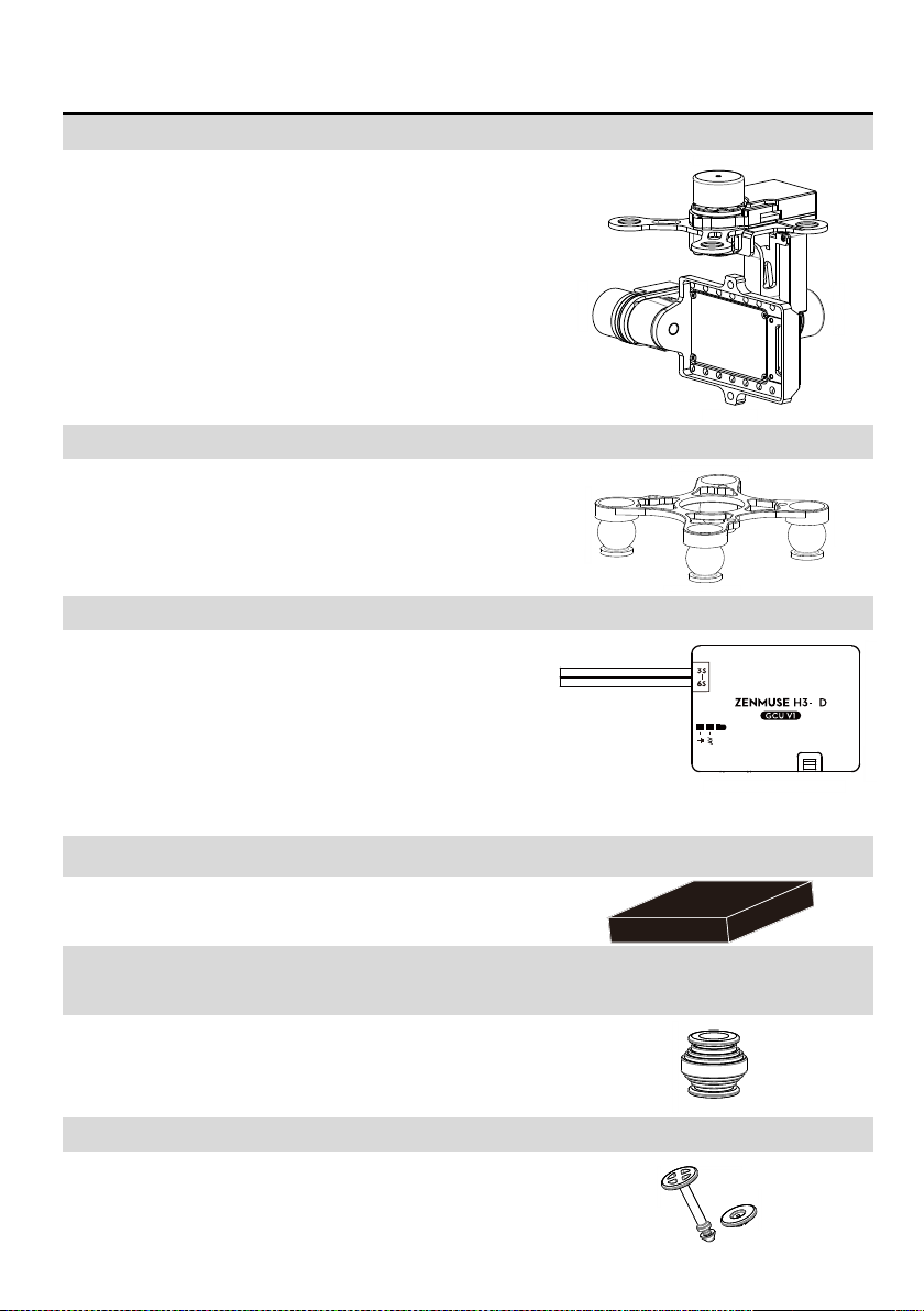
In The Box
Gimbal×1
Built-in servos and stand-alone IMU provide yaw, roll and tilt
stabilization. Integrated bottom damping plate minimizes
installation time.
Damping Unit×1
The upper plate of the damping unit connects the gimbal with the
Phantom 2. Pre-installed vibration absorbers greatly reduce the
vibrations.
Gimbal Controller Unit (GCU)×1
Connect gimbal controller to flight control system using CAN-Bus.
Power GCU and gimbal through 3S~6S power cable.
3
Accessory Pack ×1
The accessory pack includes: vibration absorbers, securing pins
and washers, screws and connection cables.
Accessory Pack – Spare Vibration Absorbers
x4
Spare vibration absorbers for damping unit with 40〬of rigidity.
Accessory Pack – Securing kits x4
Spare securing kits that are used to secure the upper and bottom
plate of the damping unit.
©2014 DJI Innovations. All Rights Reserved. 3
Page 4
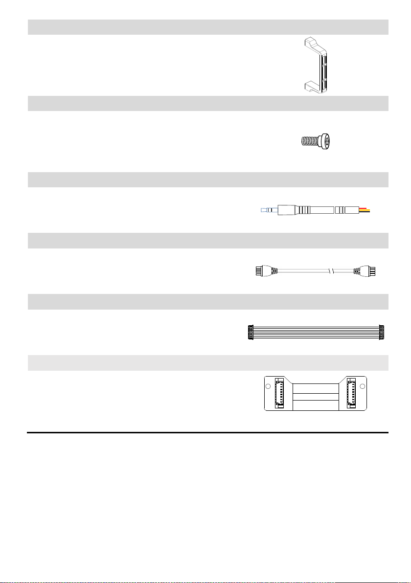
Accessory Pack – Camera securing bracket x1
Camera mounting bracket.
Accessory Pack – Spare Screws ×1
M2.5x6.3:Mounting camera to gimbal.
M2.5x5:Secure gimbal to damping unit.
M3x8, M3x6.5:Securing gimbal to aircraft.
Accessory Pack – Gimbal Video signal Cable ×1
For the gimbal controller unit and your wireless video transmission
module connection, transmitting the video signal.
Accessory Pack – CAN-Bus Cable×1
Use CAN-Bus to connect the GCU with the flight control system.
DJI
DJI
Accessory Pack – 8-Pin Cable×1
Connect to Phantom 2 or G8 port of GCU.
Accessory Pack – Anti-interference boardx1
Serves as the connector board between G8 port on the gimbal
and 8-pin cable. This board is only available to the H3-3D gimbal
that does not come with GCU unit. (namely, for Phantom 2 only
version of H3-3D)
©2014 DJI Innovations. All Rights Reserved. 4
Page 5

Table of Content
WARNING & DISCLAIMER ............................................................................................... 2
PROFILE .......................................................................................................................... 2
IN THE BOX ..................................................................................................................... 3
TABLE OF CONTENT ........................................................................................................ 5
1 INSTALLATION .............................................................................................................. 6
1.1 GIMBAL DESCRIPTION ....................................................................................................... 6
1.2 INSTALL H3-3D TO PHANTOM 2 ......................................................................................... 7
1.3 CAMERA INSTALLATION ..................................................................................................... 9
1.4 FINAL CHECKS ................................................................................................................. 9
2 GCU CONNECTION ..................................................................................................... 10
2.1 CONNECT GCU AND FLIGHT CONTROL SYSTEM ................................................................... 10
2.2 VIDEO CONNECTION. ...................................................................................................... 14
3 CONFIGURATION ....................................................................................................... 15
3.1 DRIVER AND ASSISTANT SOFTWARE INSTALLATION ................................................................ 15
3.2 ASSISTANT SOFTWARE GUI .............................................................................................. 15
3.3 CHANNEL SETTING ......................................................................................................... 15
3.4 FIRMWARE & SOFTWARE UPGRADE .................................................................................. 16
4 TEST FLY ..................................................................................................................... 17
4.1 CHECK LIST BEFORE FLIGHT ............................................................................................. 17
4.2 GIMBAL TEST ................................................................................................................ 17
APPENDIX ..................................................................................................................... 18
TROUBLE SHOOTING ............................................................................................................ 18
SETTINGS USING WITH THE A2 FLIGHT CONTROL SYSTEM............................................................ 18
SPECIFICATIONS ................................................................................................................... 20
©2014 DJI Innovations. All Rights Reserved. 5
Page 6
1 Installation
Notes:
(1) Ensure the gimbal servos are unobstructed, failure to do so may damage the servo.
(2) Clear the obstacles at once if the operating gimbal is being blocked.
(3) Always mount camera before powering on the gimbal.
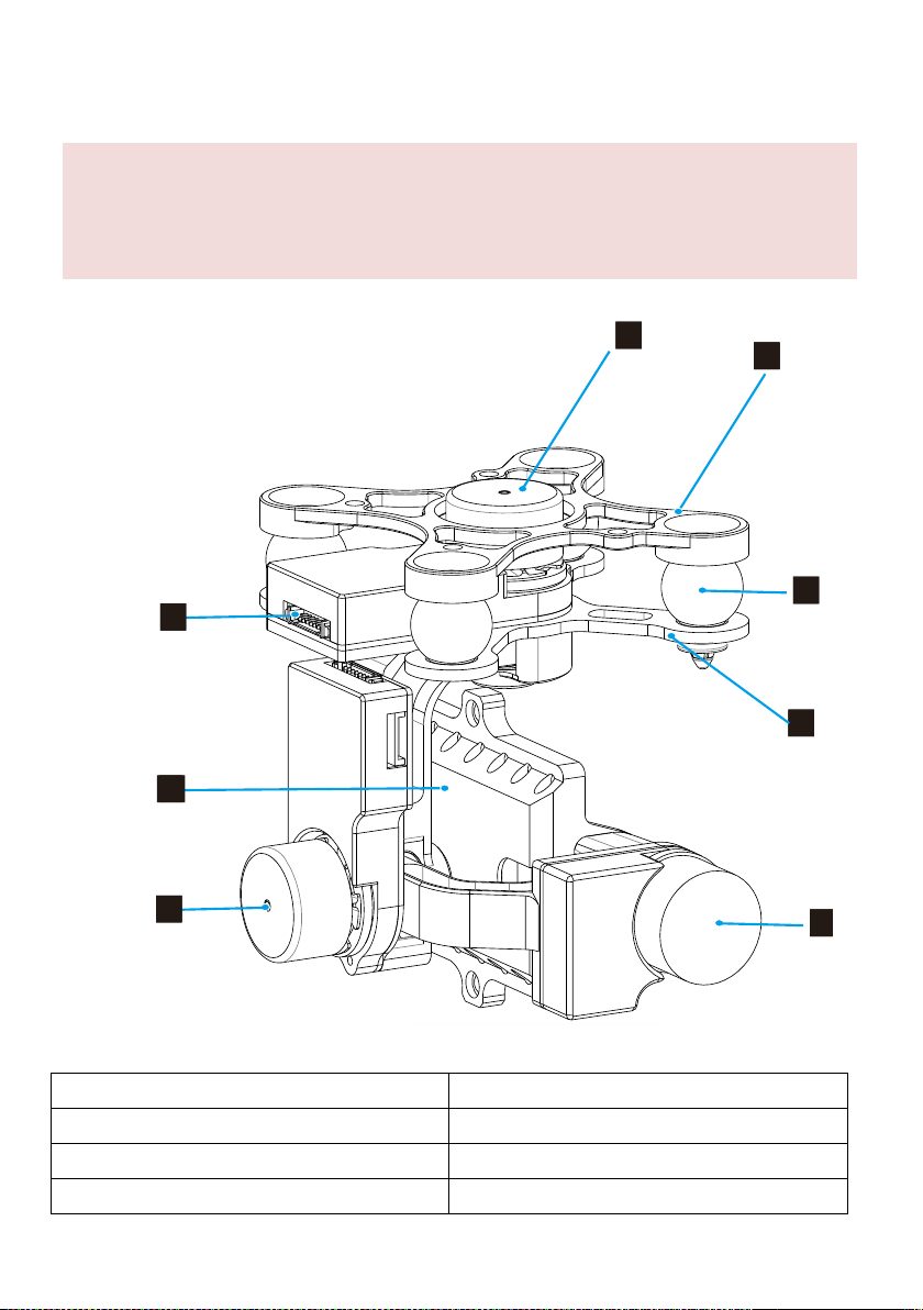
1.1.1 Rear View
11
12
13
14
16
17
18
15
1. Yaw servo driver module
2. Upper plate of damping unit
3. Vibration absorbers
4. Bottom plate of damping unit
5. Tilt servo driver module
6. Roll servo driver module
7. Camera mount
8. 8 pin connector port(to GCU/Phantom 2)
1.1 Gimbal Description
©2014 DJI Innovations. All Rights Reserved. 6
Page 7

1.2 Install H3-3D to Phantom 2
1. Insert the securing pins through the holes on the highlighted diagonal position shown below. Then, attach
and secure the upper plate of damping unit to the Phantom 2 with four M3x5 screws.
2. Attach the damping unit bottom plate to upper plate using the four vibration absorbers. Ensure the lip of
the vibration absorbers are properly inserted through the mounting holes on the bottom plate.
Follow the below instructions to install the H3-3D gimbal to Phantom 2.
©2014 DJI Innovations. All Rights Reserved. 7
Page 8

3. Insert washers into securing pins to lock the damping unit in place.
4. Plug the 8-pin cable from the Phantom 2 to the Phantom 2 port on the anti-interference enhancement
board, then connect the H3-3D port on the anti-interference enhancement board with the 8-pin port on
the gimbal via the supplied 8-pin cable.
Caution:
(1) Aircraft and accessories are not included with gimbal.
(2) Camera must be aligned with the nose of the aircraft.
(3) Gimbal is calibrated before delivery. Do not attempt to adjust or calibrate it yourself.
(4) Do not attempt to remove screws in the gimbal, which may result in reduced performance or even
damages.
(5) Do not unplug any cable attaching to the gimbal ports, or change the mechanical structure of the gimbal.
©2014 DJI Innovations. All Rights Reserved. 8
Page 9

(6) The 8-pin port on the H3-3D gimbal should only be used for connecting to the Phantom 2. Do not
connect other devices (such as a video downlink transmitter) to this port, otherwise the gimbal may be
damaged.
1.3 Camera Installation
Caution:
(1) Visit http://www.dji.com/cn/product/zenmuse-h3-3d/video, and watch installation video tutorial before
you proceed to mount the GoPro camera to the H3-3D gimbal.
(2) Ribbon cable is a delicate item, treat with extreme care. Always check the connection per each flight and
ensure the ribbon cable connection is secure.
1. Connect the video output board with the connection cable from the gimbal, ensure the connection
orientation is correct.
2. Mount the camera onto the gimbal and secure the camera with camera bracket and screws.
3. Firmly insert the video output board connector into the mini-USB port on camera to complete the
installation.
Follow the below instructions to mount the GoPro camera.
1.4 Final Checks
Ensure the installed damping unit is aligned parallel with the Phantom 2.
©2014 DJI Innovations. All Rights Reserved. 9
Page 10

GCU Port Description
3S~6S
Connect to battery for GCU or gimbal power
G8
Connect to G8 pin port on the gimbal for signal transmission
Connect to PC to upgrade firmware using Assistant Software
Connect to flight control system
Connect to wireless video downlink module
Notes:
(1) Skip this chapter if you purchase the Phantom 2 version of H3-3D gimbal, as it does not come with GCU.
(2) GCU must be connected to the flight control system before it is powered on.
(3) Be sure to mount the camera onto the gimbal before power on the aircraft and the gimbal. Otherwise it
might damage the servo due to the incorrect center of gravity setting.
(4) Re-calibrate the remote controller when NAZA-M firmware is upgraded.
(5) Ensure all the connection is correct, otherwise it might causes damage to the gimbal or the flight control
system.
2 GCU Connection
2.1 Connect GCU and Flight Control System
GCU can either be vertically or horizontally installed on the Phantom 2. Follow the procedure below to complete
the connection between the GCU and flight control system.
Step 1. Upgrade the firmware of the flight control and the Assistant Software to the latest version (as shown in the
table below)
©2014 DJI Innovations. All Rights Reserved. 10
Page 11

A2
WKM
NAZA-M V2
NAZA-M
Assistant
Software
V 1.20 (or higher)
V2.00(or higher)
V2.12(or higher)
V2.12(or higher)
Firmware
Version
V 2.10 (or higher)
V5.22(or higher)
V3.12(or higher)
V3.12(or higher)
A2
WKM
NAZA-M V2 or
NAZA-M
(1) Main Controller and
PMU connection
Connect the X1 port of
PMU to X1 port of Main
Controller.
Connect the X1 port of
PMU to X1 port of Main
Controller.
Connect the X3 port of
PMU V2 to X3 port of Main
Controller.
(2)PMU Power Cable
connection
Connect the power cable to a connecter or solder the power cable to the central
board if the DJI-multirotor is being used.
(3) GPS/Compass
Module and Flight
Control System
Connection
Connect to the CAN 2
port on the A2.
Connect the
GPS/Compass module
to spare CAN-Bus port
on PMU.
Connect the GPS/Compass
module to the GPS port of
PMU V2.
A2
WKM
NAZA-M V2
NAZA-M
(1) GCU and flight
control System
connection
Connect to the CAN
2 port on A2.
Connect the GCU to the
spare CAN-Bus port on
the WKM system.
Connect the GCU to the
CAN-Bus port on the PMU
V2 module.
(2) GCU Power Cable
connection
Connect the power cable to a connecter or solder the power cable to the central
board if the DJI-multirotor is being used.
(3) Gimbal Tilt control
channel
H3-3D
X3
X1
Step 2. Complete the connection on the flight control system (shown as the below table). For NAZA-M user, you
need a PMU V2 module (accessory of NAZA-M V2) to provide with the CAN port connection.
Refer to 2.2 GCU and DJI flight control System Connection for more information about the connection. For details
on the flight control system connection, refer to the corresponding flight control system user manuals.
Step 3. Connect the GCU to flight control system. And then connect the 8-Pin cable of gimbal to the G8 port on
the GCU.
Step 4. Connection finished. Power on the aircraft to launch.
Step 5. To fully utilize the gimbal, you also need to configure the tilt function of the gimbal. Flight control system
©2014 DJI Innovations. All Rights Reserved. 11
Page 12

assigns a specified channel (X3 channel for WKM, X1 for NAZA-M and H3-3D for A2) to control the tilt
positive pole(+)
negative pole(-)
Battery
(3S~6S)
Note:
The GCU can be connected to any CAN
ports on the PMU or to the CAN port on
the GPS.(Any spare CAN port on the
WKM system.)
To Battery
Note:
The PMU and GCU can both connect to
the same battery of LiPo 3S-6S.
Gimbal TILT Control
Control the tilt motion via the X3 channel.
Properly configure the corresponding
channel on your remote controller.
motion of the gimbal. To activate the tilt function, user needs to properly set up the channel in the Assistant
Software and ensure the connection between the receiver and the main controller is correct. Refer to the
Gimbal Assistant Software for details.
2.2 GCU and Flight Control System Connection
Fig.1 WKM Connection Diagram
©2014 DJI Innovations. All Rights Reserved. 12
Page 13

Leave as-is
To Battery
Note: The PMU and GCU can both
connect to the same battery.
Gimbal Tilt Control
Control the tilt motion via X1 channel.
Properly configure the corresponding
channel on the remote controller.
Fig.2 NAZA-M V2 Connection Diagram
Fig.3 NAZA-M Connection Diagram
©2014 DJI Innovations. All Rights Reserved. 13
Page 14

2.2 Video Connection.
Wireless Vid eo
Transmission Module
Air System
Video Signal Port
GND(Black: )
Gimbal Video Signal Cable
Video Signal
GND
Leave as-is
Video Signal(Yellow:AV)
Power
External power
1. Solder the Video Signal/GND cables to wireless video transmission module (air system).
2. Plug the gimbal video signal cable jack into the GCU video signal port.
Notes
(1) Ensure to connect the wireless video transmission unit to the GCU before powering on the aircraft.
(2) It is recommended to use standard gimbal video signal cable. Make sure you solder the gimbal video
signal cable to the wireless video transmission module firmly. Insulated all the cables to prevent short
circuiting.
Leave as-is
Video Signal Cable(AV)
GND Cable
(3) GCU does not provide power to the wireless transmission module. Refer to the wireless video
transmission module manual for details on the power supply connection.
Tips:
(1) The below diagram shows the how video signal flows from the on-board camera to the gimbal.
(2) Should error occurs, examine each checkpoints on the below diagram to locate the source of the
problem.
Camera
Video Port
Gimbal
Camera Inter face
GCU
G8
AV signal
Wireless v ideo
transmission module
Air System
8-Pins cable
Gimbal Video
Signal Cable
Wireless video
transmission module
Ground System
Wireless signal
Monitor
AV input
5.8G/2.4G/1.2G
Supplied by user
AV signal
AV signal
AV signal
Wireless video transmission transfers video signal from the on-board camera to the GCU via the gimbal video
signal cable. Follow the figure below to complete the connection.
©2014 DJI Innovations. All Rights Reserved. 14
Page 15

3 Configuration
Notes:
(1) The content of this chapter does not apply to the Phantom 2 version of the gimbal. Refer to Phantom 2
Assistant Software on the DJI website instead.
1. Ensure the drivers for the flight control system are properly installed.
2. Download the Assistant Software from DJI official website.
3. Launch Assistant Software installer and follow the prompted steps to finish installation.
4. Run the Assistant Software.
Communication indicator
Blue LED On: Lost communication
Blue LED Blink: Communicating
Red LED On: Disc onnected from PC
Green LED On: Connected with PC
Text Description
Connection indicator
Hover on the area (3) to display the information.
1
2
6
5
1
2
6
5
4
3
4
Language
中文or English
Menu
Basic: Basic function setting
Upgrade: For upgrading the gimbal firmware
Info: For version and serial number information
3
3.1 Driver and Assistant Software Installation
3.2 Assistant Software GUI
Connect GCU to the PC via a Micro-USB cable and then power on the GCU.
3.3 Channel Setting
You can adjust the range of camera tilt motion from Assistant Software by sliding the slider in the GUI.
©2014 DJI Innovations. All Rights Reserved. 15
Page 16

Fig.1 Tilt Upwards Fig.2 Tilt Downwards
1. Ensure your computer has access to the internet.
2. Close all the other applications (anti-virus application or firewall) before upgrading the firmware.
3. Make sure the power supply is securely connected. DO NOT unplug the power supply before the
upgrade completes.
4. Connect the GCU to PC through a Micro-USB cable, DO NOT disconnect the cable until firmware
upgrade completes.
5. Launch the Assistant Software and wait until connection is established.
6. Select UpgradeMain Control, IMU and CMU.
7. DJI Innovations server will check the current firmware version,
8. If a newer firmware is detected, the Assistant Software will download the upgrade the firmware
automatically.
9. Wait until the firmware upgrade completes.
10. Click OK and power cycle the system to finish the upgrade process.
Notes:
(2) CMU stands for “Camera Multi Unit”, which is management module for the camera.
(3) To eliminate the interference from the master control, it is recommended to disconnect the CAN-Bus
cable between GCU and master control before you upgrade the IMU or CMU.
(4) Double check the parameters once you have finish upgrading the firmware.
(5) Repeat (1) to (4) when the DJI server experiences heavy traffics or firmware upgrade fails.
3.4 Firmware & Software Upgrade
3.4.1 Firmware Upgrade
Follow the below procedures to upgrade the firmware upgrade, failure to do so might damage the gimbal:
3.4.2 Software Upgrade
Click Info Software Info, if the latest version is higher than the current version, you are advised to upgrade the
Assistant Software.
Obtain the serial number of the gimbal by clicking the “Info” “SN”. SN is a 32 digits authorization code that is
used to activate the gimbal. This authorization code has been filled at the manufacturing site when before its
shipment. You might be prompted to fill a new SN if you purchase a new feature in the future. If you fills an invalid
SN for more than 30 times, the gimbal will be locked and you have to contact our customer support to unlock the
gimbal.
©2014 DJI Innovations. All Rights Reserved. 16
Page 17

4 Test Fly
For safety reasons, check of the following items before each flight:
(1) Gimbal is firmly installed to aircraft, and camera mounted correctly. Make sure the camera is aligned
parallel with nose direction of the aircraft.
(2) All cables are firmly and correctly connected.
(3) Ensure gimbal video signal cable is in solid soldering condition.
(4) Make sure the wireless video transmission module is connected to GCU before powering on the system.
(5) Transmitter is properly configured.
(6) Camera connection is correct.
(7) GCU and flight control system connection is correct.
(8) Flight control firmware version is latest.
1. Ensure all the batteries are fully charged.
2. Switch on the transmitter.
3. Power on the camera first then power on the gimbal and wait until gimbal self-test completes.
4. Initialization completes, camera lens point to aircraft nose direction, that is, the three axes of gimbal
should be in the condition as the above diagram shows.
5. Toggle the tilt control switch on your transmitter, and make sure it is working properly. Then try to feel if
your gimbal moves to the corresponding direction. If not, check your settings.
6. When finishing test, power off the gimbal first then the camera.
Note:
If the gimbal is not working normally, refer to
Trouble Shooting
for solutions.
4.1 Check List Before Flight
4.2 Gimbal Test
©2014 DJI Innovations. All Rights Reserved. 17
Page 18

Place the aircraft on flat surface during the test. When conducting the test while you are holding the
aircraft by hands, bear in minds not to tilt the aircraft beyond 35°
Do not land the aircraft with powered-on gimbal on uneven terrain (such as grass lawn or rocky roads), in
which environment there may have external forces act on the gimbal otherwise the gimbal may enter
hibernation due to external forces.
Hibernation mode offers protection for the gimbal. When the gimbal is not mounted with the camera, the
gimbal enters the hibernation mode. During hibernation, the gimbal does not respond to the
transmitter’s command. The gimbal quits hibernating and resumes operation when it is mounted with the
camera.
Gimbal enters hibernation mode when it detects excessive external force is being applied, only when the
external force is no longer detected, the gimbal will restore from the hibernation.
It’s better to use separate battery pack to test the gimbal at the beginning to ensure functionality before
making steps to power on of flight controller, gimbal, OSD, FPV gears etc.
NO.
Symptom
Cause
Action
1
Gimbal keeps drifting
after initialization.
(1) Transmitter trims value is
beyond the limit.
(1) Adjust the transmitter trims value.
(2)GCU disconnects from flight
control system.
(3)Gimbal mounting is not
aligned with the aircraft.
(2)Connect GCU and flight control
system
(3)Align the gimbal mounting is
aligned with the aircraft nose.
2
Axis of the gimbal are not
level.
Factory calibration error occurs.
Contact local dealer or DJI
Innovations customer service for
assistance.
3
Unable to determine
gimbal orientation.
BVR (beyond visual range) flight
Try to use a wireless video
transmission module.
Appendix
Trouble Shooting
Settings Using with the A2 Flight Control System
Users should configure the H3-3D’s pitch control in the A2 assistant software when using with the A2 Flight
Control System. Map the H3-3D channel to a switch on the transmitter. It is recommended to use a knob switch
channel, which is only used for H3-3D pitch control on the “Channel Map” page (as the following diagram shown).
©2014 DJI Innovations. All Rights Reserved. 18
Page 19

©2014 DJI Innovations. All Rights Reserved. 19
Page 20

Specifications
General
Built-In Functions
(1) 3-axis gimbal
(2) High precision brushless servo control
(3) Aluminum alloy body
(4) Built-in IMU module
(5) Lightweight
(6) A2, WKM, NAZA-M, NAZA-M V2 ,PHANTOM 2 supported
(7) GoPro3 and GoPro3+ supported
(8) Zenmuse technology
Peripheral
Supported Camera
GoPro3, GoPro3+ (black or silver version)
GCU Input Power
3S~6S LiPo (12V~26V)
Assistant Software System Requirement
Windows XP SP3; Windows 7; Windows 8
Mechanical & Electrical Characteristics
Working Current
Static current: 400mA (@12V)
Dynamic current: 600mA (@12V)
Gimbal Input Power
3S~6S (12V ~26V)
Operating Temperature
-10°C ~ 50°C
Gimbal Weight
168g(camera excluded)
Gimbal Dimensions (With Damping Unit)
97mm X 95mm X 73mm
GCU Weight
22g
GCU Dimensions
42 mm X32 mm X9.3 mm
Working Performance
Controlled Angle Accuracy
Pitch/Roll:±0.02°, Yaw: ±0.03°
Maximum Controlled Rotation Speed
Tilt axis: ±130°/s
Controlled Rotation Range
Tilt axis control: -130~+45°
Regulatory Approvals
FCC (USA)
Yes
CE (EU)
Yes
ROHS(EU)
Yes
©2014 DJI Innovations. All Rights Reserved. 20
 Loading...