

Page 1
1
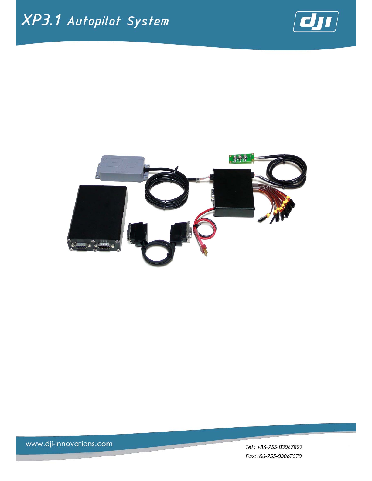
DJI XP3.1 Standard Manual
V 1.01
DJI Innovation Technology
Address: Room 1205, Business Park
Shenzhen University-town, Lishan Rd,
Nanshan District, Shenzhen, Guangdong,
P.R.China
P.C:518000
Tel: 0755-83067827
Fax:0755-83067370
URL: http://www.dji-innovations.com/
Email:info@dji-innovation.com
Page 2

2
Contents
PREFACE ........................................................................................................................................4
1 INTRODUCTION...........................................................................................................................4
1.1 FUNCTION INTRODUCTION ......................................................................................................4
1.1.1System Features.....................................................................................................4
1.1.2 Hardware System .................................................................................................5
1.1.3 Control Mode........................................................................................................5
1.2 SYSTEM REQUIREMENT............................................................................................................7
2. SYSTEM........................................................................................................................................9
2.1 SYSTEM FRAMEWORK .............................................................................................................9
2.2MODULE INTRODUCTION ......................................................................................................10
2.2.1Main Controller ....................................................................................................10
2.2.2 Adapter ...............................................................................................................10
2.2.3 GPS & Compass..................................................................................................11
2.2.4 LED Status Indicator............................................................................................11
2.2.5 Software ..............................................................................................................11
3 SYSTEM INSTALLATION AND ADJUSTMENT...........................................................................12
3.1 HARDWARE INSTALLATION ....................................................................................................12
3.1.1 Main Controller Installation................................................................................12
3.1.2 Adapter installation............................................................................................15
3.2 SYSTEM PARAMETERS TUNING AND SETTING ............................................................................21
3.2.1 Tuning Preparation .............................................................................................21
3.2.2 The Primary Setting of Remote Control ............................................................21
3.2.3 Completion of the First Test Flight Adjustment by Software Wizard ..............22
4 OUTDOORS FLYING ADJUSTMENT...........................................................................................33
4.1 HELICOPTER FLYING ADJUSTMENT AND TEST UNDER MANUAL MODE..........................................33
4.2 FAIL SAFE SETTING ...............................................................................................................34
4.3 COMPASS CALIBRATION ......................................................................................................34
4.4 FLIGHT TEST UNDER AUTOPILOT MODE....................................................................................35
4.4.1 Setting Meanings and Related Regulation Methods of Parameters............36
4.4.2 Flying Test.............................................................................................................38
4.4.3 Flight Success: .....................................................................................................39
4.5 POINTS FOR ATTENTION IN FLYING..........................................................................................39
4.5.1 Preflight Examination Process ...........................................................................39
4.5.2 Flying Attention Points........................................................................................40
4.5.3 Landing Explanation ..........................................................................................42
3 APPENDIX..................................................................................................................................43
APPENDIX A: LED STATUS INDICATOR ..........................................................................................43
APPENDIX B: ELECTRICAL CHARACTERISTICS ................................................................................44
Page 3

3
APPENDIX C: MECHANICAL PROPERTIES......................................................................................44
APPENDIX D: MECHANICAL DRAWING .......................................................................................45
APPENDIX E: PACKAGING LIST....................................................................................................48
APPENDIX F: SAFETY CHECK LIST .................................................................................................48
Page 4

4
Preface
Please read this brochure carefully before using DJI XP 3.1. If you have any
questions, please contact with us. We will give you satisfying answers as quickly as
possible. Our company will not supply service to the product from improper channel
or with unclear functions.
Our company reserves the right to revise any part of this brochure without
informing users beforehand.
1 Introduction
1.1 Function Introduction
DJI XP3.1 is a controlling system for unmanned system, integrated with GPS,
6-DOF inertial measuring unit, Magnetic-field meter and barometer. The system
could control the helicopter precisely and reliably at any flight altitude, in most
weather conditions, and even under the short-interruption of GPS signal situation.
1.1.1System Features
Helicopter, a non-stable platform itself, needs continuous observation and
controlling to keep steady flight. DJI XP3.1 provides excellent auto stable hovering
and flight performance by adopting GPS/INS inertial navigation technology, which is
widely used on cruise missile, and advanced controlling algorithms.
Main Characteristics of DJI XP3.1
1. Autonomously hovering with high precision.
2. When autonomously hovering, the helicopter altitude and position can be
locked. Flight velocity in one direction corresponds a given RC stick volume,
so users can control a fool-style flight( can only control one channel at one
time)
3. Under the locked altitude, with the help of XP 3.1, operators can easily
control the helicopter to do the turn-coordination.
4. Amend errors raised between hovering and flying automatically.
5. The main differences between DJI XP3.1 and the stability augmentations
stem based on CCD sensor: DJI XP3.1 can to any altitude within the remote
Page 5
5
control smoothly, without the height and surface texture restraints. No
frequent switching between various modes, the speed can be accreted to
0.1m/s or less.
6. Automatically turn into hovering state when receiver signal is lost (enter the
Fail Safe mode).
1.1.2 Hardware System
1. Improve the accuracy and real-time performance of the controller by using
2 separate DSPs (digital signal processor) to calculate altitude and control
algorithm.
2. Provide superior position accuracy by using a high performance 16-channel
GPS receiver.
3. Enclose high-reliability tri-axial gyroscopes and accelerometers of MEMS.
4. Building algorithm can facilitate users to do the hard and soft iron magnetic
field compensation for eliminate the magnetic interference.
5. The system dedicates CPLD to decode and encode servo signal for higher
reliability and compatibility for most RC receivers.
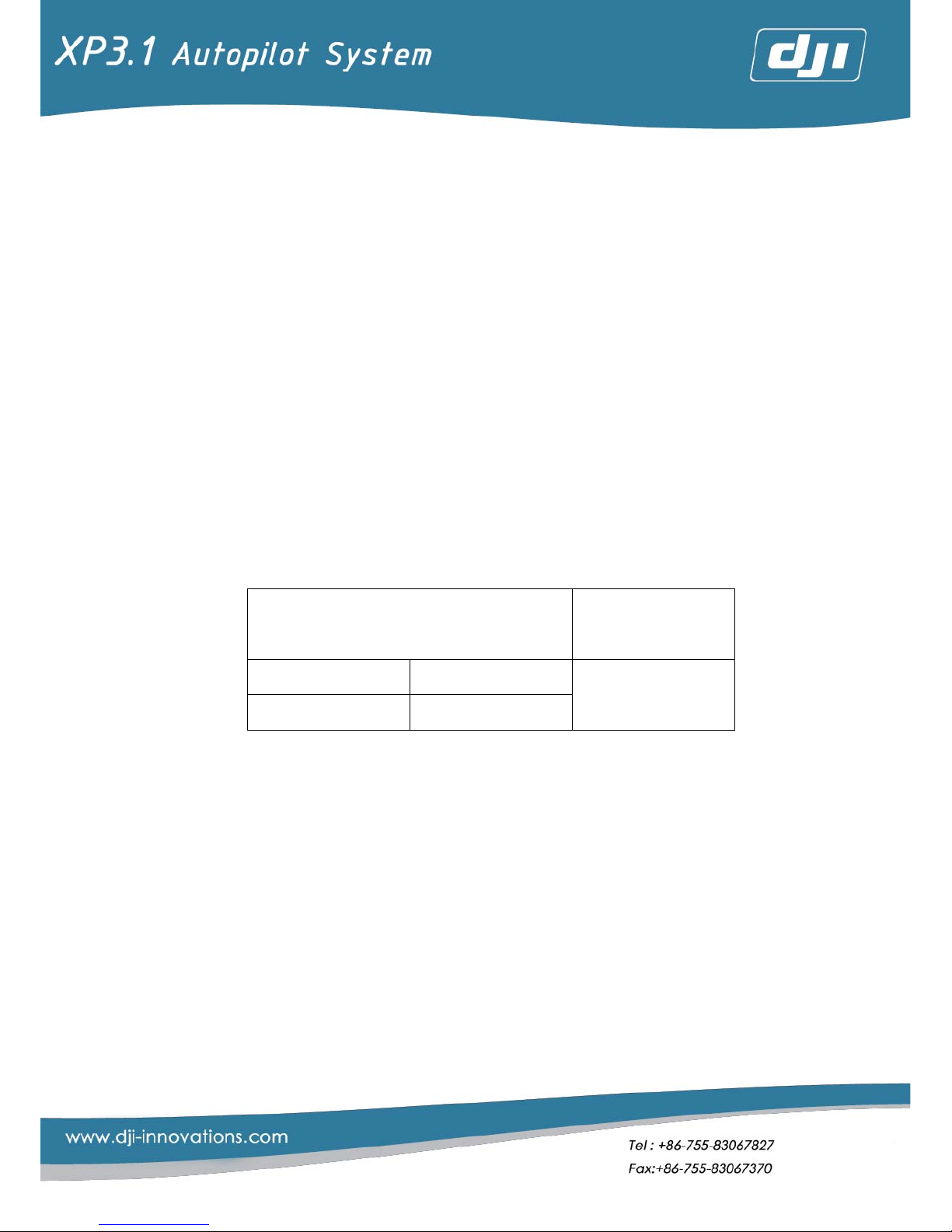
【The Basic Performance Parameters】
Hover positioning accuracy
○
1
Maximum wind
resistance
Vertical ±1m
Horizontal ±2m
5.5~7.9m/s
Note:
○1 : These parameters are measured in the condition of breeze (wind speed less than 3.3m/s). If in heavier
wind, the accuracy will be little lower.
1.1.3 Control Mode
【Autopilot Mode】:
In this mode, the altitude can be locked; the nose direction and the
helicopter’s velocity command, back and forth, left and right, up and down, can
be issued by RC separately and get accurate feedback control through on-board
automatic control algorithm. Even people, who are flying the RC helicopter for their
first time, can learn to control the helicopter in few minutes.
There is a hovering zone
○1
in the middle of the RC stick. When the RC stick goes
back to the middle and enters the hovering zone, the system will make the
Page 6
6
helicopter enter auto-hovering in a short time.
After entering autopilot mode, the flight speed is in proportion to the volume of
RC stick
○2
.
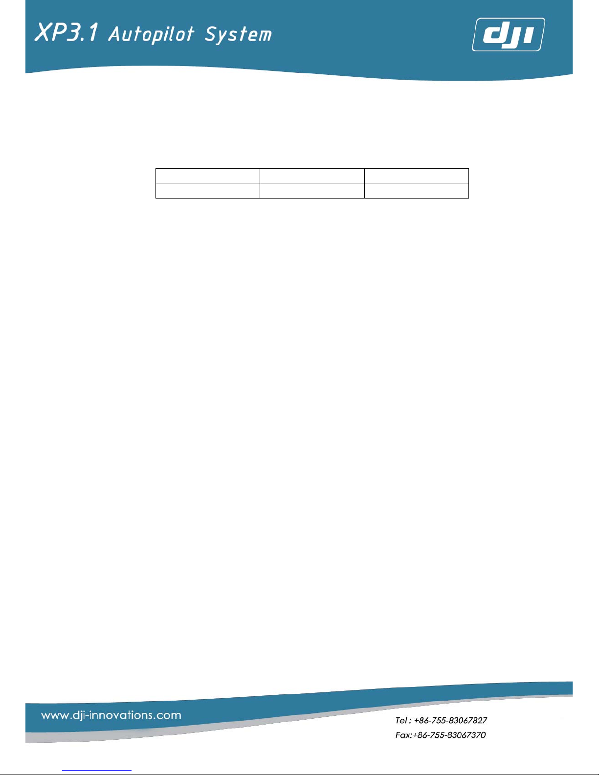
When the RC stick is pushed to the limit, the corresponding maximum flight
speeds are as followings:
Forward-Backward Left-Right Up-Down
±30km/h ○3 ±14.4km/h ±7.2km/h
Note:
○1 :The small section of the hovering zone on the RC is determined by the system controller.
○2 :The ROTOR EPM is locked by GV1 or ESC.
○3 :In order to keep helicopter in safe range, system velocity is intentionally limited within 30m/h.
【Pure Manual Mode】:
The system remains the traditional manual mode. Under this mode, operator
can control the helicopter as ordinary RC helicopter.
Page 7

7
1.2 System Requirement
Helicopter Types
Applicable to electrical and gas/fuel powered
helicopters
Ordinary mode
CCPM
1_Servo_Norm
Swash Types
CCPM mode
1. 3_Servo_120°
2. 3_Servo_140°
3. 3_Servo_90°
4. 4_Servo_90°
Remote Controller
1. 7 channels or more
2. All channels have the Fail Safe function
○1
System Operating
Temperature
-10 ~ +70℃
System Operating
Voltage
7.4~12V(DC)
Recommended
System Power
Supply
The specifications of lithium battery as followings:
○2
Voltage: 7.4V ○3
Battery capacity: More than 2000mAH
Discharging current: Larger than 5C
Recommended
Accessories
1. Gyroscope:GY401
○4
2. Speed controller: ESC (electromotion), GV1
(kerosene-powered) practicably locking the
revolving speed)
○5
3. Receiver(PCM)
○6
or 2.4G
Note:
○1 : Some of the RCs (like some kinds of Spektrum RC), only the throttle (the first channel) has the function of
Fail Safe, none of the other channels have Fail Safe function. Under such situation, it cannot guarantee
that the helicopter can enter the auto-hovering state when the RC is in the out of range.
○2 :For the lithium battery of these specifications, the voltage can reach more than 8V when it is at full
power state (there are two 3.7V batteries connected in series inside. If there are three 3.7v batteries
connected in series, it may exceed the system operating voltage, so it is not recommended). If the
measured voltage is 7.4v, the battery is at the edge of being empty. As a result of adopting powerful
DSP+ARM to process efficient attitude control algorithms, the system working current may approach
Page 8

8
more than 1A. By using the lithium battery with capacity is over 2000mAH, the system can work for
around 2hours
○3 : System alarming voltage is 7.4v (under this condition the red LED status indicator will always on)
○4 : The gyroscopes will induce this change (and confirm it is not artificial operation), and emend this impact.
After testing, the compatibility between GY401 and XP3.1 is higher than that between GY601 and
XP3.1, so GY 401 is recommended.
○5 :Engine governor such as GV-1 or RPM lock-able motor drivers are required to maintain a constant rotor
RPM and XP3.1 will leave the Thro channel in the original position in the autonomous mode.
○6 :PCM or 2.4 G receivers has Fail Safe function, but PPM Do not.
Page 9
9
2 System
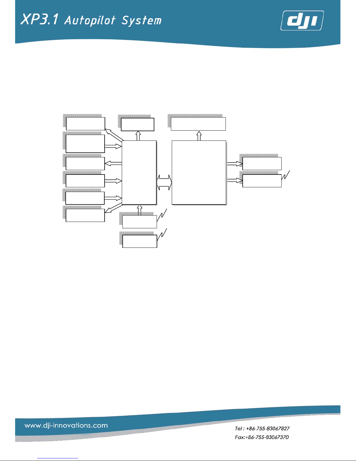
2.1 System Framework
Note:
■Black: Normal configured mode
■Blue: Optimal configured mode
■Brown: User-configured mode
Receiver
RC
Servo
Ext. ports
LED
GV1/ESC.
Power
Gyroscope
Compass
&GPS
Adapter
Gyro Stable P&T
SD Card
Wireless
Main Controller
Page 10

10
2.2Module Introduction
2.2.1Main Controller
Main Controller, which calculates the flight attitude and control the
helicopter’s flight by sending orders to Adapter under autopilot mode, is the heart
of the control system.
Figure 2. 1 Main Controller
2.2.2 Adapter
Adapter acknowledges signals from RC receiver, process controlling signal and
control the servo operation with cooperation of Main Controller.
Figure 2. 2 Adapter
Page 11
11
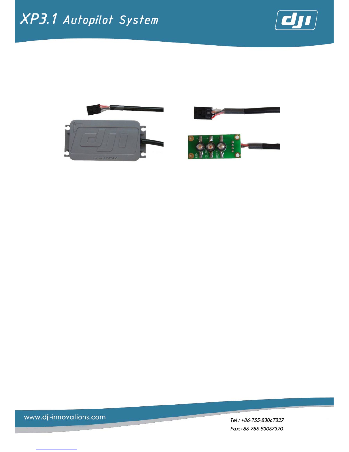
2.2.3 GPS & Compass
External GPS and compass are integrated in one box. Both of them must be
placed far away from interference. It is used to receive GPS signals and direction
signals, and send them to Main Controller.
Figure 2. 3 GPS&Compass Figure 2. 4 LED Status Indicator
2.2.4 LED Status Indicator
LED with red, white and green ones will have constantly on, sparkling, flashing
and constantly off states. They represent different control status respectively (Refer
Appendix A for details).
2.2.5 Software
A PC software named XP configure is for the system adjustment. Users need to
set different parameters for different helicopter to make sure the system operate
normally.
Page 12
12
3 System Installation and Adjustment
Users should dedicate special circumspection and patience to the
installation, adjusting, flying and maintenance of the system. Any improper
operation may lead losses of helicopter, life or property. Please pay special
attention to the following steps and introductions of installation and adjustment. Do
not try to skip any step.
This sign stands for “Fatal Danger”. Users should pay special attention to it
and handle with care.
3.1 Hardware Installation
Before you install XP 3.1, please make sure the mechanical structure of the
helicopter has been adjusted completely
○1
and the helicopter can process normal
manual flight in the absence of this system.
Note:
○1 :Try to eliminate all kinds of vibrations by adjusting mechanical structure and motor system, since the
oversize vibration will influence the normal operation seriously.
3.1.1 Main Controller Installation
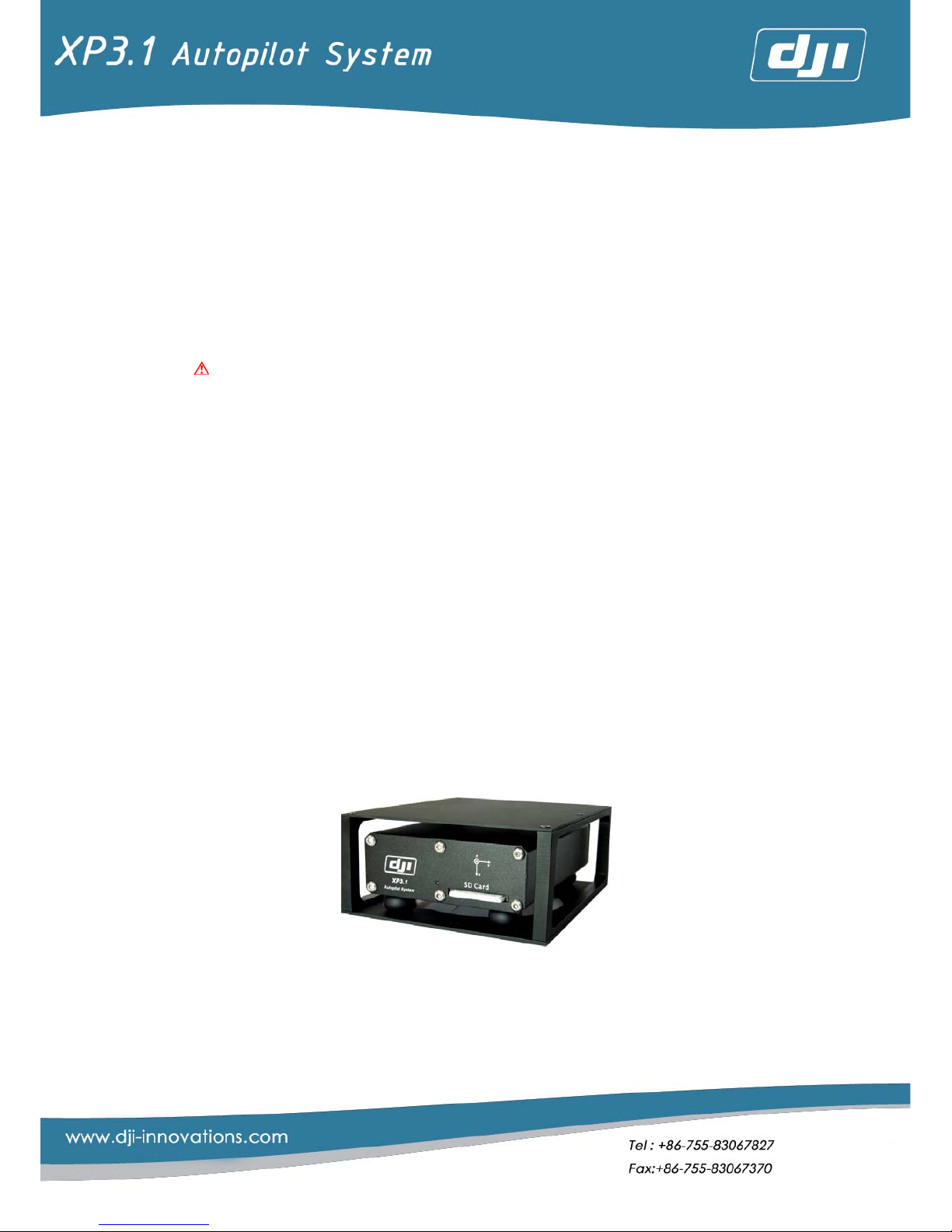
1. Please assemble the anti-vibration frame of the main box first. The Main
Controller can be fixed on the anti-vibration frame of main box by 4 neoprene
isolators, as shown in Figure 3.1.
Figure 3. 1
2. Main Controller installation can follow the following two ways, with reference
of the coordinate frames of Main Controller (Figure 3. 2) and helicopter(Figure
3. 3). Inversion or installation in other angles is not allowed.
Page 13
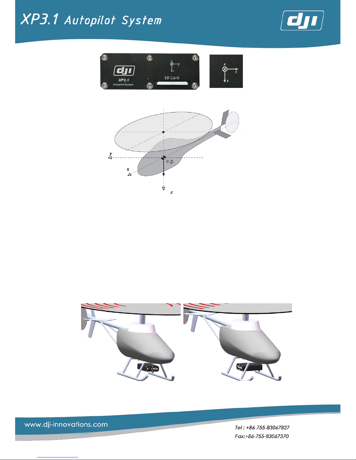
13
Figure 3. 2
Figure 3. 3
a) (Figure 3.4) Make Main Controller box frame the same direction as the
helicopter frame, which means the side with two DB ports faces the
head of the heli, corresponding to the “Forward” set by the [Install
Parameters] in XP configure(adjust software).
b) (Figure 3.5Figure3. 4 Figure3. )Make Axis X of
Main Controller the same as axis Y of helicopter, which means the side
with two DB ports faces the right direction of the heli, corresponding to
the “Right” set by the [Install Param] in XP configure. Make Axis X of
Main Controller the same as axis Y of helicopter, which means the side
with two DB ports faces the right direction of the heli, corresponding to
the “Right” set by the [Install Param] in XP configure.
Figure3. 4 Figure3. 5
Page 14
14
Attention:
1) For the helicopter with gasoline engine and electric motor, the
minimum distance between the Main Controller and the engine/motor
is 10cm; but for the heli with methanol machine, one does not need to
consider the distance between them.
2) The distance between the Main Controller and the center of gravity
should be close enough, the shorter the better. Also to avoid being
blown by the airflow caused by the rotation of the main rotor.
3) The installation direction should as straight as possible, or it will decrease
the control accuracy.
4) The Main Controller should be far away from heat sources,
electromagnetic interference and servo.
5) 在 Users should reserve enough space for the insertion of connecting
wires to Adapter or to the computer in front side of the Main Controller
(the side with two DB ports).
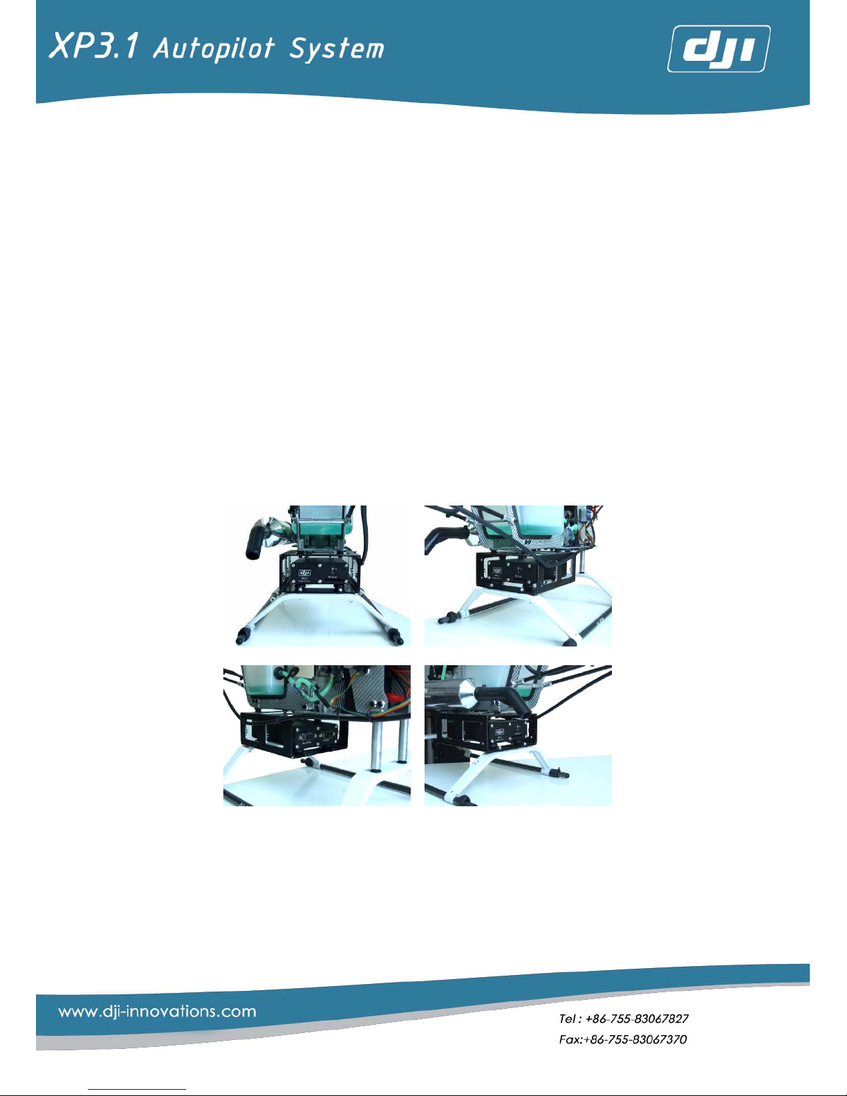
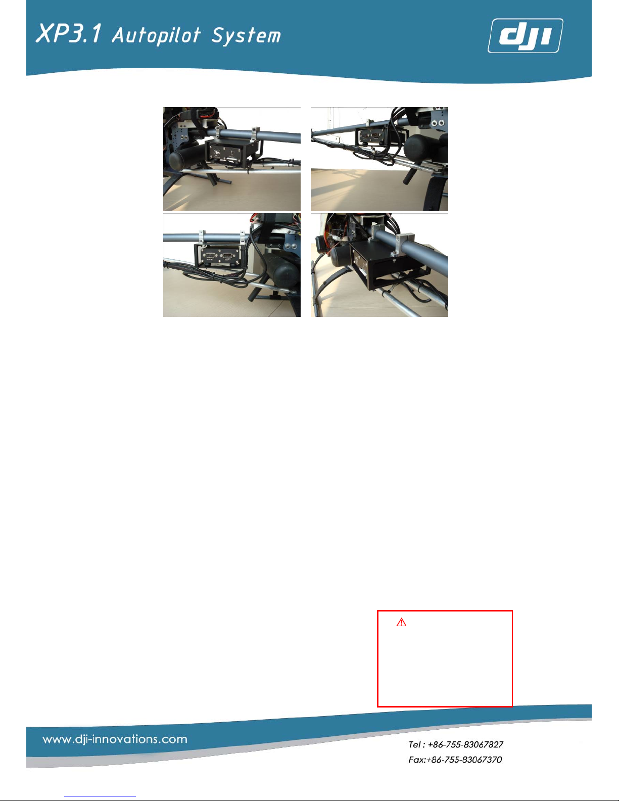
3. Users can find a suitable position
○
1
for the Main Controller according to the
above requests and helicopter’s structure. Followings are two installation
examples (Figure3. 6 and Figure 3. 7).
Figure3. 6
Page 15
15
Pay attention to
protect DB15 cable and
avoid long-time friction,
which may leads
short-circuit or open-
circuit!
Figure 3. 7
Note:
○1 : Drill proper holes on anti-vibration frame and helicopter. Then fix the anti-vibration frame to
the helicopter.
Attention:
Check the bearing capacity of neoprene isolator regularly to see if it has the
tendencies of weakness or aging, in order to replace it in time.
3.1.2 Adapter installation
1. 【Position Choice of Adapter】:
1) The minimum distance between the Adapter and the engine (gasoline
engine or electric motor) must be 10cm at least, or normal work will be
disturbed.
2) Arrange a proper position for Adapter installation to reduce the using of the
extension wire because there are many links between Adapter and RC
receiver, servo respectively.
3) Do not fix the Adapter to the helicopter after choosing a proper position. Fix it
after all the adjustment.
2. 【 Connection between Main Controller and
Adapter】:Connect them by DB 15 cable (Figure
3. 8), which matches DJI XP3.1. The clasp of DB
15 cable must be locked (Figure3. 9 DB15 open
status) (Figure3. 10 DB15 closed status). The
looseness of DB15’s clasp must be avoided.
Page 16

16
The routing should not be pulled to tightly (Figure 3. 11) longer wire in advance
is preferred and. Do not constrain the DB15, which links to the port of the Main
Controller. Keep it reflex to avoid affecting the attitude of the Main Controller
or reducing the efficiency of isolators. The recommended way is shown in
Figure 3. 12
Figure 3. 8 DB15 Cable Figure3. 9 Open Status Figure3. 10 Closed Status
Figure 3. 11 Figure 3. 12
3. 【Connection between RC Receiver and Adapter】:Fix the RC receiver first.
And then connect Adapter’s input wire to the RC receiver according to the
label on them (Figure 3. 13) and the power polarity. No external power supply
is needed for RC receiver, because its power has been supplied by Adapter
directly (Figure 3. 14).
Figure 3. 13 Figure 3. 14
Definitions of the RC receiver input wires are shown as follow:
Label T A E R U
○
1
P G○2 X
Definition
THRO AILE ELEV RUDD AUTO PITCH GYRO AUX
Page 17

17
No other links
except input wires of
Adapter are allowed to
connect to the RC
receiver, for example:
Servo or electronic
shutters.
Note:
○1 : Autopilot/ manual channel
○2 : Gyro sensitivity channel
Connection schematic diagrams:
Figure 3. 15
Figure 3. 16
Attention:
JR and Futaba RC receivers are promoted,
because in this manual we set them as
examples. By using them users could make
connection according to the above two charts.
Please check if the channel definition of the RC
receiver corresponds to that of the above
charts. If not, the former is promoted. If the RC
receivers are other models, users should
connect them with definitions of wires.
4. 【Connection between Servo and Adapter】:As in Figure, the 8 marked ports
are output channels to the Servos (Figure 3.17). Servo power supply (4.8v) is
connected to the BATT channel of Adapter. The connection is the same as
that of connecting between RC receiver and Servo. The followings are the
schematic diagrams of swash plates with three servos (including normal mode,
90°CCPM,120°CCPM,140°CCPM) and four servos (90°CCPM). Please
follow the following connection(Figure3. 18 and Figure 3. 19)
Page 18

18
Figure 3. 17
Figure3. 18 3-servo Swash
Figure 3. 19 4-servo Swash
Attention:
Power supply of the Servos and the control system are two mutually
independent and different ones. The Servos are supplied by power source of 4.8v
battery and is inserted in the BATT port. Please install a switch between the servos’
Page 19

19
No GPS & Compass
cannot work normally if
access to other ports.
battery and the port. The controller system is supplied by the 7.4v battery. The
switch on Adapter is the power switch of control system.
5. 【Connection between LED Status Indicator and Adapter 】:Connect LED
status indicator (Figure 3.20) to the interface of the status indicator on the
Adapter according to the corresponding joint of the status indicator (Figure 3.
21) please install the indicator in the place where can be seen easily from
different directions when helicopter flying. Users can refer to the following
graphic (Figure 3. 22).
Figure 3. 20 Figure 3. 21
Figure 3. 22
6. 【 Connection between the External GPS &
Compass and Adapter 】: There are four
extended ports on the Adapter to connect
some relevant airborne modules such as the
external GPS &Compass, wireless video transmission (matching), ground
station radio (professional edition matching) and so on. No. 1 port is the input
port for GPS & Compass signal (Figure 3. 24). The upper surface (DJI trademark
surface) of GPS & Compass should be upward. It should be laid flat in the
Page 20

20
coincident direction of the coordinate frame on box and one of the
helicopter (output wire points to the head of helicopter). No occluded objects
are allowed around. It should be installed at the half of the tail pipe
approximately, and let it be far away from the servo.(Figure 3.25)
Figure 3. 23 Figure 3. 24
Recommended Installation:
Figure 3. 25
Attention:
1) Signals’ reception will be affected if GPS is too near to the main rotor
or Servo; the accuracy of the GPS data computation may decrease
when it is too near to the tail rotor
2) Distance between the external compass and servo should be more
than 20cm, while that between compass and the engine should more
than 30cm.
3) The tail boom must be adopted carbon fiber and nonmagnetic
material (the material will not be absorbed by magnet). The screws
near the compass must be adopted stainless steel. If you are not sure if
the material near the compass is magnetic, you can use the magnet or
the ordinary compass to check.
4) If there are some ferromagnetic materials which the maximum
dimension is x near the compass, the minimal distance between
ferromagnetic materials and the compass should be 2x
Page 21

21
3.2 System Parameters Tuning and Setting
If users follow the above installment process, then you should finish the
connection of the hardware. Now we will start the parameter tuning and the setting
by software.
3.2.1 Tuning Preparation
1. 【Software Installation】:Please install the USB to Serial Port Cable driver. exe of
the ancillary CD and XP Configure 1.20(system parameters tuning software)
2. 【Power and Connection】:Connect Adapter to the 7.4v power. Link one end
of the cable (Figure 3. 26) to the DB9 port of the Main Controller’s front panel
(Figure 3. 27), and link the other end to the USB connection of the computer.
Servo power is not turned on if it is not related to Servo.
Figure 3. 26 Figure 3. 27
3. 【System Booting】:Turn on the system power switch and pay attention to the
LED Status Indicator. Refer to appendix A1 [normal booting mode] to see if
booting is normal. If not, please refer to appendix A4 [error status], check if the
installation is correct and reboot it. Refer to appendix A2 [normal operating
mode] to check the twinkle of the indicator after normal booting. If users
tuning indoor, the red LED indicator should flash for no GPS signal.
4. 【Software Connecting】:Open XP configure software, and then it will search
for available COM port automatically. If no mistake happening when
connecting, it will connect to the Main Controller automatically. It shows the
system has been connected normally and smoothly when the connection
indicator of the software turns to green. As the chart.
3.2.2 The Primary Setting of Remote Control
All the settings made through remote controller by users have been reserved.
Among them, two places are needed to be set first, swash type setting and
autopilot switch setting.
1. 【Swash Type Setting
○
1
】:Regardless of the brands of the remote controller,
Page 22

22
please alter the swash type in remote controller to helicopter-Normal one.
That’s means, each servo link to the swash plate independently.
Note:
○1 :JR RC: Choose NORM in SWASH TYPE
Futaba RC: Choose HELICOPTER, H-1 in PARAMETER
2. 【Autopilot Switch Setting】:Users need to set a two-position self-convenient
switch on RC as the autopilot switch to switch between manual mode and
autopilot mode
Attention:
If users make connections according to the above explanation completely,
the channel 5 of JR RC is the autopilot setting channel, while the channel 7of
FUTABA RC.
3.2.3 Completion of the First Test Flight Adjustment by Software Wizard
Users can turn on the control system power (Don’t turn on the servo’s power)
after finishing preparation and remote control setting. Enter the software adjustable
interface after the normal starting of the system. When the indicator on the left of
the window turns to green from red, the software begins to work. And then, users
can enter adjusting wizard interface (Figure 3. 29) by single-click “Wizard” button
upleft (Figure 3. 28).
Figure 3. 28
Page 23

23
Figure 3. 29
Attention:
Please don’t turn on the servo power in case of being burnt out because of
the locking braking.
STEP1. 【Main Controller and GPS Offset Setting】
After entering the first interface, click “next” to enter Main Controller and
GPS offset setting interface (Figure 3. 30).
1) The Direction of the Main Controller
Please refer to 【3.1.1 Main Controller installation】, then choose the
installation direction of the Main Controller accordingly (forward or right)
Figure 3. 30
Page 24

24
2) the Offset of the Main Controller Installation
Offset: offset is the coordinate value of the target object in a coordinate
frame which is an x-y-z coordinate frame with the helicopter’c. g.
○1
(center of gravity) the origin point. For example, if the Main Controller is
laid at point A, A’s coordinate value is the offset of Main Controller
(Figure 3. 31).
Figure 3. 31
Users can measure the offset values according to the position of the Main
Controller and the helicopter’s c. g, and fill them in the proper position
showing as following diagram
Figure 3. 32
Page 25

25
3) If GPS antenna is laid at Point B, then B’ coordinate value is the offset of
GPS (Figure 3. 32).
As for the same reason, users can get GPS offset by the position of
GPS installation. If users install it at the point of 1/2 length of the tail pipe
approximately, the offset values of y and z is usually 0. Then users only
need to find out the distance between GPS and the c.g. of helicopter in x
direction. Pay attention to the positive and negative of GPS’s offset
value in x direction, and it should be always negative.
Attention:
1. By default, users do not need to change the offset value of GPS in y and
z directions in the software. But if the users do not install GPS in the
recommended position, you can modify the value of y and z by clicking
“Advanced”nearby.
2. To set the expected parameters into the Main Controller to finish setting,
do click “write” after filling the parameters in
3. “Meter” is the unit of all the offset parameters
Note:
○1: The way to determine the c.g. of helicopter: take down the main rotor, tie the long line with gravity
hammer to the tail pipe, raise the helicopter’s tail, and let the helicopter and the ling hang down
naturally. Then the intersection point of the line and the helicopter is the c.g. of helicopter.。
STEP2. 【Autopilot/ Manual Mode Setting】
1) Click “next” button after finishing the operations above to enter
autopilot/manual mode setting. After turning on the remote control, users
can try to shift autopilot/manual switch. Then users can notice the slide
also shifts between the topside and bottom side, which shows the
autopilot/manual switch, has linked correctly. Users should set the switch
normal and reverse according to the slide direction (upward pushing,
slide locates upward side, and vice verse)
2)
○2
In the default situation, the TRVL ADJ (End Point in Futaba) of
manual/autopilot channel should be 100%. Transfer the up and down
TRVL ADJ to 0% and set this position as Fail Safe. Refer to the Figure 3. 34
after turn off the RC. 4.2 Fail Safe setting will lead users to complete the
unfinished part of fail safe setting.
Page 26

26
Figure 3. 33
3) Users should find out the autopilot/manual switching channel(if you follow
the above tips strictly, they should be channel 5 or 7, corresponding JR or
Futaba remote controller) to enter TRVL ADJ setting of remote control.
Reduce its max value, and users could notice the slide approaches to the
red line or green one gradually. When there is a trimming little slide on the
left side of the red line or green one, it means the adjustment in this
direction has been finished (Figure 3. 33). That of the other direction can
be finished in the same way.
Page 27

27
Figure 3. 34
Attention:
If JR remote controller is adopted, the TRVL ADJ setting value should be
about 80%, While in Futaba being 60% more or less. Moreover, if FUTABA
remote controller is adopted, slide movement can be noticed by reducing
fewer than 80%.
4) When switch is upside, the slide leveling with the red line, the green LED
should vanish constantly, and then it is the manual mode. When switch is
downside, the slide leveling with the green line, the green LED indicator
should begin to sparkle, which shows having entered into auto mode. If
users can get all above, you have finished the adjustment. Please click
“next” to continue the next step.
Note:
○1 :It should be TRVL ADJ in JR RC or END POINT in Futaba RC.
○2 :This step has set a third mode beyond autopilot and manual mode. Helicopter will enter fail safe mode
if the RC receiver loses signals. Control system will enter fail safe once autopilot/manual switch
enter any position beyond the two fixed ones set in step3. So any position (Figure 3. 34) is acceptable
if users do not set fail safe as the approach position of autopilot or manual.
STEP3. 【Swash Type Setting】:
Under the manual mode, users can adjust the helicopter according to
the requirements for ordinary remote-controller helicopter.
1) Before this step, set the swash type as NORMAL mode remote controller first。
2) If your helicopter is Not CCPM mode, set the Swash types as NORMAL in the
software (Figure 3. 35). click “write ”and then “next” to enter the
interface of “Feedback & Servo Calibration”。
Swash Type:
Swash Type Ccpm Parameter
Normal Type Normal -
Swash Mix
Ccpm Type
1. 3_Servo_120°
2. 3_Servo_140°
3. 3_Servo_90°
4. 4_Servo_90°
NORM 、REV(Servo Rotation Direction)
Page 28

28
Figure 3. 35
Figure 3. 36
3) If it is CCPM mode (Figure 3. 36), parameters of swash mix and Servo
direction should be set correctly.
a) First turn the TRAV ADJ (End Point) of every channel of control stick
which controls PITCH, AILE, RUDD, ELEV to the maxima.
b) Check if the setting of swash type is NORM mode in remote controller.
c) The moving direction of swash plate is decided by the rotation direction
of Servos and the sigh (positive or negative) of swash mix, while its
motion amplitude is decided by the values of corresponding swash mix.
¾ Push PITCH stick up and down and notice if all the Servos lead the
Page 29

29
swash plate moving horizontally, that means every servo lets the
swash plate up or down coordinately. If not, click
“NORM””REV” buttons to adjust the direction of Servo.
¾ Push PITCH stick, the forward and backward movements
correspond the changes of collective pitch of main rotor. If the
direction is opposite, change the sign of PITCH in swash mix.
¾ Push ELEV stick forward and backward should correspond the
forward and backward rotation of swash plate. The adjusting
methods are the same as above.
¾ Push AIL stick right and left should correspond the right and left
rotation of swash plate. The adjusting methods are the same as
above.
4) It the swash slants slightly, users can do trim tuning by remote controller. If
the inclination is too big, please adjust the mechanical median of swash
plate. Users can refer to the installation manual of the helicopter for details.
¾
Figure 3. 37
5) Pay special attention to CCPM 4_Servo_90 Swash type (Figure 3. 37)。
¾ Connect the pull rods of three Servos, for example, the left, front
and right Servos.
¾ In the software interface of “swash setup”, configure the Swash
types and the directions of the three Servos.
¾ Connect the pull rod of the fourth Servo after complete adjustment
of the three ones. And adjust the direction of the fourth, to make
sure no locking braking
○1
between Servos and the correct motion of
swash.
Page 30

30
Note:○1: No “Kaka” sound from Servo.
6) Adjust the minimal collective pitch to -2 °,maximal one to 10-11 (guarantee
the corresponding climbing speed more than 3m/s) and median one 5 by
the software and PITCH curve in remote controller.
7) Click “next” after finishing the settings, to enter the interface of
“Feedback & Servo Calibration”.
STEP4. 【Feedback & Servo Calibration】
This step can get the calibration of stick volume and feedback control. The
main purpose is to get positive and negative directions and the maximum
minimum values of all channels.
Figure 3. 38
a) Enter the interface of [Feedback & Servo Calibration] (Figure 3. 38), and
click the “Cal” buttons of AILE、ELEV、RUDD、PITCH orderly.
Attention:
The channels of throttle and PITCH are mixed, so you are adjusting
throttle channel either when you calibrate the pitch channel. If it is an
electronic helicopter, users need to set the last point of the throttle curve
to the maximal when processing calibration of PITCH channel. Do reset it
to the settings before after finish pitch channel calibration.
b) After entering calibration interface, push the stick to the center first;
then click “Ok” (Figure 3. 39) and push stick according to the arrow
pointing direction shown from software (Figure 3. 40); Return the stick to
the center finally. Software will exit the calibration interface
automatically after the calibration of the corresponding channels.
Page 31

31
Figure 3. 39
Figure 3. 40
Attention:
Make sure the duration of the stick at the endpoint more than 2
seconds.
c) Users push the stick and check if the directions of stick is the same as
shown in software.(stick to left or upward corresponds the slide shown in
software moving upward; stick to right or downward corresponds the
slide shown in software moving downward). If calibrated correctly, the
top or the left end of the stick should correspond the top position of the
slide. Meanwhile, the bottom or the right end of the stick should
correspond the bottom of the slide. If the slide reaches the top or
bottom too early, or it cannot reach there, re-calibration is needed.
d) Feedback Test.
¾ Switch the remote controller to auto mode or the prompt box will
appear (Figure 3.41).
¾ Click “Feedback Test” button.
¾ Now, users need to check the swash plate. The swash plate will
move automatically. The directions as followings: collective pitch:
up—down; swash plate tilting: front- back-left-right; Rudder:
Page 32

32
The correctness of
《Feedback test》and
《Controller Orientation
Test》will affect the
normal operation of the
Main Controller.
left-right; throttle: up- down. If the directions are inconsistent, users
need to re-calibration corresponding channels.
¾ Switch back to the manual mode and withdraw the test.
Figure 3.41
e) Switch the remote controller to auto
mode(or the prompt box as above will
appear)
f) After clicking “Controller Orientation
Test” button
¾ When helicopter inclines left, the
swash will tilt right.
¾ When helicopter inclines right, the
swash will tilt left.
¾ When helicopter inclines front, the swash will tilt back.
¾ When helicopter inclines back, the swash will tilt front。
¾ Switch back to the manual mode and withdraw the test
Note: The Main Controller will keep swash plate as horizontal as possible. Tilting horizontal angel 10°
of helicopter will lead biggest moving amplitude of swash.
g) If the directions are not as the above, users should recheck the
installation of the main box. Then re-click “Feedback Test” to check if
everything works normally. Or re-calibration the feedback direction.
Refer to [Swash setup] [Main Controller Installation] [Instrall Param].
STEP5. After the above tests complete, fix the Adapter on the helicopter to
prepare for the outdoors flying test.
Page 33

33
The main purpose is
to get the optimum
performance under
manual mode in this
adjustment. Pleas Never
try to shift to auto mode
when flying.
4 Outdoors Flying Adjustment
Please read through this chapter before flying outdoors. Peruse 【4.5 Points for
Attention in Flying】 before flight. Please operate carefully to avoid any accident!
4.1 Helicopter Flying Adjustment and Test under Manual Mode
1) Test the RC antenna’s radio distance: take
down the main blades and turn on the
engine at the first test; then shorten the
antenna, do the test about 20m away from
the helicopter under manual mode. If the
green LED enters the auto mode, which is
sparkle, it indicates that RC is out of range.
Now, the user need to check if the installation
positions of Adapter and RC receiver are far away from interference sources
as engine, especially the gasoline engine.
2) After completing the installation and adjustment as an ordinary
remote-control helicopter, users can process the complete flying
adjustment under the manual mode and reach the stable flight
performance
○1
.
3) Keep the helicopter stable temporarily even if the helicopter is not in control
ling for seconds by tuning the trimming of RC. Now, users need to remember
the general position of PITCH stick
○2
Note:
○1: With the inertial system in the control system, vibration of helicopter will cause the control of the
Main Controller to be at an unstable state. So, to display the best performance of the whole system,
users need to reduce the vibration to the smallest。
¾ Balance the main rotor to avoid “twin screw phenomenon”. Users need to adjust the
helicopter to a condition which it is almost impossible to notice the vibration by naked eyes.
¾ Adjust the mechanical center point of helicopter, especially tail rotor. Under the unlocking
mode of the helicopter’s gyro, adjust the mechanical center point of the tail rotor. When
hands off the stick, no obvious rotation is allowed and guarantee of helicopter’s temporary
hovering is needed.
¾ Push the rudder stick to the left/right endpoint and ensure the rotation speed of tail at 1
circle per 2 seconds in left/right direction. After the adjustment, users can switch it to the
locking mode of gyro.
Page 34

34
○2 :The reason for making the PITCH stick in the center when helicopter is hovering by adjusting
PITCH curve is to set them as the corresponding fail safe positions in the next step [fail safe setting].
4.2 Fail Safe Setting
The purpose of setting fail safe is to let helicopter hover still under fail safe
mode when it loses signals from remote controller. Tips as followings:
1) The fail safe position has already been set as 0% (center) when users do PC
software setting.
2) Set other channels as hovering center points in he fail safe option of remote
control, to make it convenient for XP3.1 to supervise if the communication of
remote control is normal and respond in time.
3) To observe if the green LED Status Indicator will flash after turning off the
remote controller.
4.3 Compass Calibration
1) 【Entering into the Compass Calibration Mode】:Under the manual mode,
shift the autopilot/manual switch to and fro ten times quickly (being back
and forth as one time).then it will enter the compass calibration status and
the green LED will be constantly on。
2) 【Horizontal Axis Calibration】:When the red LED is off, keep the helicopter
horizon (the white LED will be constantly on) and rotate the helicopter 3-4
circles slowly in horizon. When rotating, make the white LED on as constantly
as possible. (Refer the video of compass calibration for details). After
finishing the calibration of horizontal axis, continue that of the vertical axis.
Attention:
If the white LED is off, it means the helicopter deviate from the horizontal
angle too much. Then, users should adjust the position of helicopter, and keep
it at the horizontal position and do rotation again.
3) 【Vertical Axis Calibration】:When erect the helicopter (head down), the
red LED will constantly on. Then keep the white LED constantly on and rotate
the helicopter 3-4 circles slowly by the longitudinal axis (refer the video of
compass calibration for details).
4) 【Whether to Save the Calibration Date】:
a) Saving Calibration Data:Shift the autopilot/manual switch ten times
quickly, then all three LED will flash for 5 seconds, which means the
success of the data saving and the existing from the compass
calibration mode(the green LED will be off). Please restart the system
Page 35

35
after the calibration.
b) Quit without Saving:If users don’t want to save the new data, shift the
autopilot/manual switch once. Then it will abandon the calibration data
and quit from the compass calibration mode (the green LED will be off).
5) Reboot the system
6) 【Inspection after the calibration】:Under the normal work mode, rotate the
helicopter ten times clockwise, 90°for each time, and notice the white LED
on or off. Stay 5 seconds between two operations at least。
a) Calibration Succeed:After the all rotations, the times of rotations with
the white LED no-flash reach 8 in 10 at least。
b) Calibration Failure:After the all rotations, the times of rotations indicator
flash more than 2 in 10. Then users need to do compass calibration once
again.
Attention:
1) Pay attention that there should not be any magnetic or iron materials near
by, such as magnet, automobile, steel bar under ground and so on.
2) Ensure the slow rotation during the calibration, and keep the white LED
constantly on。
3) Maintaining the helicopter horizon and rotating it 3-4 circles is that to
guarantee the system can get data for any angle in 360°.
4) Recalibration in the following situations:
a) Any modification of the helicopter, such as the installation of new
electronic equipment, replacement of gyro, the change of Main
Controller installation position, changes of other mechanical structure
and the change of battery installation position.
b) In the flight process, the deviation of flying direction is too big.
c) The helicopter turns backward frequently and the orange indicator
starts to glitter (but it is normal occasionally).
5) DJI-XP3.1 is not suitable to work in Antarctic Circle or Arctic Circle, because
the magnetic heading system will be invalidation or near to it.
4.4 Flight Test under Autopilot Mode
The helicopter can fly normally after all adjustment under manual mode. The
following steps will help users make parameter tuning in autopilot mode to complete
helicopter’s autopilot flight.
Page 36

36
4.4.1 Setting Meanings and Related Regulation Methods of Parameters
1. The parameter of autopilot is on the first page of XP configure software
“control gain”, as shown in Figure 4. 1. At present, 4 parameters on software
layout are opened for tuning. Roll_Gain is the parameter to adjust the roll
direction(right-left)movement of helicopter, as shown in Figure 4. 2; Pitch_Gain
is the parameter to adjust the pitching direction (forward-backward)
movement of helicopter, as shown in Figure 4. 3; Yaw_Gain is the parameter to
adjust the tail rotation direction movement of helicopter, as shown in Figure
4. 4; Vertical_Gain is the parameter to adjust the vertical direction movement
of helicopter, as shown in Figure 4. 5.
Figure 4. 1
Figure 4. 2 Figure 4. 3 Figure 4. 4 Figure 4. 5
Roll Pitch Yaw Vertical
Page 37

37
Before taking off,
please read 【4.5 points
for attention in flying】.
Taking off is forbidden
under an
y
unusual
Special Tips:
The tuning of these four values is similar to the tuning of sensitivity of
helicopter’s tail gyro. If the value is too big, high frequency shaking in according
direction will occur. If the value is too small, it cannot lock the position in this
direction and drifts cyclic slowly.
2. Click “Default” to restore the default values,
and then click “write”. After writing of default
values, users can attempt autopilot flight with
these parameters。
3. Users should read through this section then
entering 【4.4.2 flight test】. Please make the
helicopter hover stable under the manual mode and switch to the auto mode.
Please pay close attention to the helicopter status after entering autopilot:
¾ Roll_Gain:
If there is high frequency shaking in the roll direction (refer to video), it
means Roll_Gain value is too big. Please switch to manual mode in time, land
the helicopter and reduce the according parameter. The coarse tuning can
be about 20 each time.
If left-right cyclic drifting appears (refer to the video), it means the
Roll_Gain is too small. Please switch to manual mode, land the helicopter and
increase this parameter. Regulation methods are the same as above.
¾ Pitch_Gain:
Normally, no high frequency shaking will happen in this direction, so users
can set a relatively higher value in this direction. Generally speaking, the value
of Pitch_Gain is 1.5 times of Roll-Gain.
¾ Yaw_Gain:
With the existence of the tail-locked gyro and the proper adjustment of its
sensitivity, normally no high frequency shaking or low frequency drifting will
appear in this direction. This value can be understood as Rudder speed, the
higher the faster. But please pay attention, under the auto mode, the tail
speed is relatively slow. So please do not compare it with that under manual
mode. If the value is too big, high frequency shaking of tail will occur.
¾ Vertical_Gain:
If high frequency shaking happens in the vertical direction (refer to the
video), it means the value of Vertical_Gain is too big. Please switch to manual
mode in time, land the helicopter and reduce the value. The coarse
adjustment can be 3-5each time.
If vertical up-down cyclic drifting appears (refer to the video), it means
the Vertical_Gain is too small. Please switch to manual mode, land the
helicopter and increase this parameter. Regulation methods are the same as
Page 38

38
When first entering
the autopilot hovering
mode, please prepare
for switching to manual
mode momentarily。
Please land the
helicopter under
manual mode in all
these ste
p
s.
above.
¾ Normal status:
When parameter tuning is proper in every direction, helicopter may hover
stable (refers to the video). Users can try to pull the sticks of every direction
orderly (one scale is suggested) to perceive the acceleration and the stable
level in the process of stopping. If it reacts too slow to start or stop in some
direction when flying, please increase the value in this direction.
Attention:
1) Two or more phenomenon listed above may appear during adjusting,
but please adjust one parameter at one time. After the unusual
phenomenon disappears, adjust the parameter in another direction.
2) Relatively 15% smaller than the critical value is promoted, to guarantee
no high frequency shaking under various flight status will happen (similar
to gyro sensitivity tuning).
3) During adjusting process, please switch to manual mode at once when
any unstable phenomenon appears.
4) Users can resume the default parameter in control gain at any time
through software.
4.4.2 Flying Test
Before flying test, please read 【4.5 points for attention in flying】 and
【 Appendix F Special Security Checking 】 and then carry on the following
operations.
1. Flying Test : Users must to control helicopter
hovering stable in manual mode before the first
autopilot hovering. And then switch to auto
mode by the autopilot/manual switch of
remote controller, to keep it hovering.
a) Please switch to manual mode at once
when any unstable phenomenon appears。After it hovers stably, make it
enter auto mode again.
b) If unstable performance appears many times when helicopter enters
the auto mode
¾ Users need to land the helicopter
under manual mode and readjust
related parameters. Refer to related
tips of adjusting flight parameters in
【4.4.1 Setting Meanings and Related
Regulation Methods of Parameters 】(related video).
Page 39

39
¾ Please check if the helicopter is adjusted as ordinary RC-helicopter.
This time, users need to carry out the operations from the step of
【4.1 Helicopter Flying Adjustment and Test under Manual Mode】.
4.4.3 Flight Success:
Congratulations! If you reach this step successfully, it means your helicopter
can work normally. But for the deuteric maintenance, you need to carry out
carefully. Before flight every time, please read 4.5 points for attention in flying in
flight and [Appendix F special security check carefully] and do the
corresponding security check。
4.5 Points for Attention in Flying
4.5.1 Preflight Examination Process
1. Check all the joints and electric wires, to see if the joints loose or the wires are
wear.
2. Check if the RC receiver receives signals normally. Do not put out the antenna
first. Put it 10-20m far away from the helicopter and remote-control test if the
Servo can work normally.
3. Wait for 3 minutes after power on and examine the starting status of the three
LEDs:
1) There are two situations when system starts successfully:
a) 【With SD Card】:LEDs will go out orderly.
b) 【Without SD Card】:After the first LED (red) goes off. The second one
(white) will go off after the first one (red) flashes 5 times continuously. The
green indicator will go off at last.
Attention: SD card is suggested because it can be used as black box。
2) Starting failure and its solutions:
a) Check the connection first, and power on again.
b) If the LEDs do not go off for more than 2 minutes, reboot
c) 【Three LEDs flash simultaneously】:It means the attitude or controller
start unsuccessfully. Please lay the helicopter horizontally and power on
again. Parameters can be set by PC software
d) 【Three LEDs flash in streamline】:It means reading failure from E
2
PROM
data. Please reset parameters such as swash type by PC software.
4. Wait until GPS receives the signals, examine the condition of the red LED:
1) 【Constantly off】:Perfect signals. Good situation for flying.
Page 40

40
Never try to switch
to autopilot mode when
the red LED is flashing.
2) 【 Sparkling 】: Strong signals. Taking off is
allowed, but the safety coefficient decreases,
so users should avoid flying as possible as you
can.
3) 【 Flash 】: Weak signals. Taking off is not
allowed. Please recheck the connection of GPS antenna or adjust at
spacious places.
Note: when there is no GPS, it is normal phenomenon for swash tilting slowly when the system enters the
auto mode.
5. Turn on the remote controller. Then shift the autopilot/manual switch and
examine the condition of the green LED:
1) 【Sparkling】:Autopilot mode
2) 【Constantly off】:Manual mode
6. Switch into the autopilot mode and check if the swash tilts. If it does, reboot
system.
Note: If the swash moves up and down when entering the auto mode by autopilot/manual switch, that is
because the atmospheric pressure is unstable on the ground. It is normal.
7. Manual test: check if the swash plate movement is correct.
Note: It is normal that the swash move in a small range by pushing the stick under the auto mode.
8. Rotate the helicopter repeatedly for several times, 90° for each time. And
check the condition of the white LED.
9. After no abnormities appear during inspection, start the engine, and examine if
the LED status indicator has any abnormity (refer to appendix A for details)
10. If no abnormal status appears, users can take off the helicopter manually (red
LED cannot flash).
4.5.2 Flying Attention Points
1. The points needing attention before entering auto mode
1) Guarantee the attitude is good (white LED does not lighting).
2) GPS signal is good (red LED does not flash). Users should avoid flying the
helicopter at places with shutters, such as tunnels, cities with tall buildings,
because these shutters will affect the receipt of the GPS signals. It is suitable
to fly at spacious places, such as squares.
Attention:Even when the red LED is under the condition of sparkling in flying,
users can also switch to auto mode, but the safety coefficient could reduce.
So users should avoid flying in such situations.
Page 41

41
3) After the helicopter hovering by manual-control, switch to the auto mode.
Followings are some possible problems and solutions:
a) 【Stick’s offset from center is not big】:Its influence to the system is small.
The system can revise by itself.
b) 【stick’s offset from center is big and the helicopter has the drifting
tendency】:Shift the manual/autopilot switch to manual mode to make
the helicopter hover stable, and then enter auto mode again.
2. After hovering under manual mode, switch to autopilot mode, then it can enter
autopilot mode. Then, users can control the helicopter in the directions of up
and down, back and forth, left and right by stick. Shift the autopilot/manual
switch at any time may reenter the manual mode.
Attention
Please do not push any stick when shifting the autopilot switch. Or, helicopter
may not hover, but drift to some direction slowly after entering the auto mode. If in
such situation, users do not need to worry. Please switch to manual mode and then
back to auto mode with motionless.
Note: ○1 : Main controller can set the servo value, the time user shift into auto mode, as the feedback center
point.
3. During the auto flight, pay attention to the statement of the white LED:
1) 【Constantly off】:Good attitude status.
2) 【 Sparkling 】: It means there is some slight error about the attitude
computation. At this time, don’t make violent movements of helicopter.
Especially do not keep the helicopter rotating continuously. Or it will cause
the disorder of the attitude computation. So, please keep hovering till the
white LED go off.
3) 【Flashing】:
a) If there is no tendency of out of control, it does not matter if it flashes
temporarily.
b) If the helicopter has the tendency of out of control, it means the
attitude computation is unusual. Then users should switch to manual
mode and land the helicopter as soon as possible. Flying after rebooting
the system.
Attention:
1) The probability for the white LED to sparkle or flash is small during the
Page 42

42
flight. It may happen only when it is bumped or it rotates with a high
speed (4 seconds or less per circle) for a long time.
2) Avoid rotation continuously for a long time, for instance: it rotates for
more than 3 circles continuously and the speed surpasses 4 seconds per
circle.
3) The angular speed should not surpass 300
0
per second in every flight
direction, or problems may rise. In such situation, the system can make
the flight attitude recover automatically, but there may be some errors
during the recovery procedure.
4. 【Exit From Auto Mode】:Guarantee remote controller can communicate
normally, and users can switch to manual mode to fly momentarily.
4.5.3 Landing Explanation
The helicopter can land under both auto mode and manual mode.
1) 【Landing Under the Auto Mode】:
a) Choose the proper landing position.
b) The helicopter is hovering stable.
c) Down the helicopter slowly.
d) At the moment of landing, pull the throttle to the lowest point and
switch to the manual mode immediately.
Attention:
There is near surface effect within 1.5 rotor radii, so the helicopter is not stable.
It will drift even under the auto mode. So please do not stay within such altitude for
a long time.
2) 【 Landing Under the Manual Mode 】: Landing as the ordinary
remote-control helicopter.
Page 43

43
3 Appendix
Appendix A: LED status indicator
1.【Normal starting status】:
1) With SD card: All three LEDs are on, and then go off in the order of red,
white and green.
2) Without SD card: All three LEDs are on. After the red LED goes off. The
white one will go off after the red one flashes 5 times continuously. The
green one will go off at last.
2.【Normal status】:
Note:
1) Sparkling:One time per second
2) Flashing:Five times per second
3.【compass calibration mode】: After completeness of the compass calibration
and all three LED flash for five seconds, please restart the system.
Color Red White Green
Constantly
Off
Vertical axis
Calibration
±3º
○4
Compass
Calibration
Constantly
On
Longitudinal
axis
Calibration
Not in proper angle
range
-
Note:
○1 :More than 7 satellites
○2 :5~6 satellite;
○3 :Less than 5 satellites
○4 :±3º:When compass calibration, helicopter tilts from horizon within 3º
4. 【Error status】:
1) The three indicators do not go off(for more than 5 minutes): Unknown
status.
2) All three LEDs flash at the same time: the failure of attitude or controller
Color Red White Green
Constantly Off GPS Strong○1 Attitude Good Manual
Sparkling GPS Medium○2Attitude Medium Autopilot
Flashing GPS Weak○3 Attitude Disorder Signal Lost
Constantly On Power Alarm - Compass Calibration
Page 44

44
starting.
3) Three LEDs flash in streamline state: The failure-reading of E
2
PROM data.
Appendix B: Electrical Characteristics
Operate
Temperature
-10 ~ +75℃
Power
Consumption
5W
Input Voltage 7.4~12V(DC)
Appendix C: Mechanical Properties
Weight(g) Size(mm3)
Main Controller
Box
245 110*78*29
Adapter Box 130 90*62*22
GPS&Compass
Box
80 90*44*20
Page 45

45
Appendix D: Mechanical Drawing
All units are in millimeter in following
1. 【Structure of Main Controller box】
Page 46

46
2. 【Structure of Adapter box】
3. 【Structure of anti-vibration frame】
Page 47

47
【Front view of Main Controller in frame】
【Right view of Main Controller in frame】
4. 【COMPASS/GPS MODULE DRAWING】
Page 48

48
Appendix E: Packaging List
XP3.1 Standard
1) Main controller 1piece
2) Adapter 1piece
3) Compass&GPS module 1piece
4) Anti-Vibration Frame 1piece
5) LED Status Indicator 1piece
6) Neoprene Isolators 8pieces
7) DB15 connection Cable 1piece
8) USB to Serial Cable 1piece
9) SD card 1piece
10) Product CD 1piece
Appendix F: Safety Check List
User should pay special attention to the points listed below, otherwise will lead
to Fatal danger!
1. Is adapter installed more than 20cm away from Gas engine?
2. Is the Fail safe function on the RC transmitter correctly set?
3. Make sure the “Feed back Test” and the “Controller Orientation Test”
passed correctly
4. Have you done the compass calibration, and check the result?
5. Do a RC transmitter Range test.
 Loading...