

Page 1
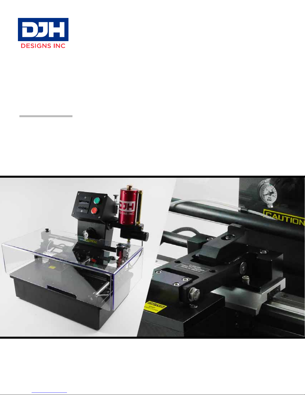
MEK RUB TEST MACHINE
USER MANUAL
Everything you need to know about setting up & using your MEK Rub Test Machine by DJH Designs Inc.
Page 2

©Copyright DJH Designs Inc. 2018
All Rights Reserved. Reproduction, adaptation, or translation without prior written permission is prohibited,
except as allowed under the copyright laws.
Publication number :: A20029-9500M
First Edition , January 1992
First Revision, September 1994
Second Edition, June 1995
ird Edition February 1997
Fourth edition January 2000
Revised November 2003
Fih Edition January 2007
Revised February 2008
Sixth Edition January 2010
Eigth Edition May 2018
Printed in Canada.
Warranty
e information contained in this document is subject to change without notice.
DJH Designs Inc. Makes no warranty of any kind with regard to this material, including, but not limited to,
the implied warranties or merchantability and tness for a particular purpose.
DJH Designs Inc. shall not be liable for errors contained herein or for the incidental consequential damages in
connection with the furnishing, performance, or use of this material.
Page 3

INDEX
Section Page
Manual Conventions 4
Unpacking & Installation 5
Installing MEK Reservoir 6
Air Supply Connection 8
Installing the Safety Cover 9
Replacing the Rubbing Pad 10
Filling the MEK Reservoir 11
Testing a Panel 12
Adjusting the Rubbing Block 15
Setting the Number of Strokes 16
Running the Rub Test 17
Maintenance 18
Machine Specications 19
Where to Find Help 20
Warranty 21
Repackaging Guidelines 22
Survice & Support 24
Service Request Form 25
Hardware Installation 26
3
Page 4

MANUAL CONVENTIONS
To help you nd important information quickly, and make instructions easier to understand, this manual uses the
following conventions:
Italic refers to a document title or is used for emphasis.
Bold refers to new terms or is used for emphasis.
NOTE
CAUTION
WARNING
TIP
Notes contain important information set o from the text.
Caution messages appear before procedures which, if not observed, could result in inaccurate
data or in damage to the equipment.
Warning messages alert you to a specic procedure or practice which, if not followed
correctly, could cause serious personal injury.
Contains helpful information about a procedure or practice
4
Page 5
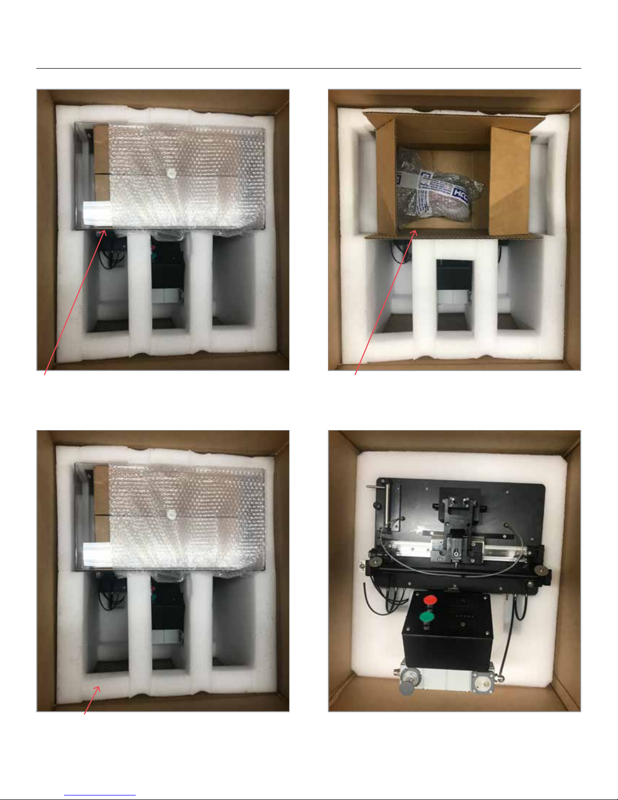
UNPACKING MACHINE
1. When rst opening the box, rst remove the safety
cover, then remove other components underneath.
2. Remove box underneath safety cover containing
the MEK resevoire.
3. Remove foam insert 4. With the help of another person, carefully li the
MEK machine base from the box.
5
Page 6

MACHINE INSTALLATION
Select a suitable area for the machine. e machine weight is 62.5 lbs. (30 kg) and must be installed on a sturdy
work bench that will be able to absorb the inertia of the dead weight rubbing block being shuttled back and forth.
It is recommended that the work area have at least 30cm clearance on all sides.
e machine comes with two (2) mounting plates to secure the machine to the tabletop. Please refer to the diagram
below for recommended method of installation. Place the anti-skate pads under the corners of the machine as
shown. For metal bench tops mark the screw locations drill pilot holes and then screw the brackets onto the
worktable surface. For wood benches and surfaces simply attach using #10 wood screws.
Anti-Skid Pad
WARNING
Failure to secure the machine to the work table may result in the machine falling o the table, serious damage
to the machine and or personal injury can occur due to the weight of the machine.
6
Page 7
UNPACKING & INSTALLATION
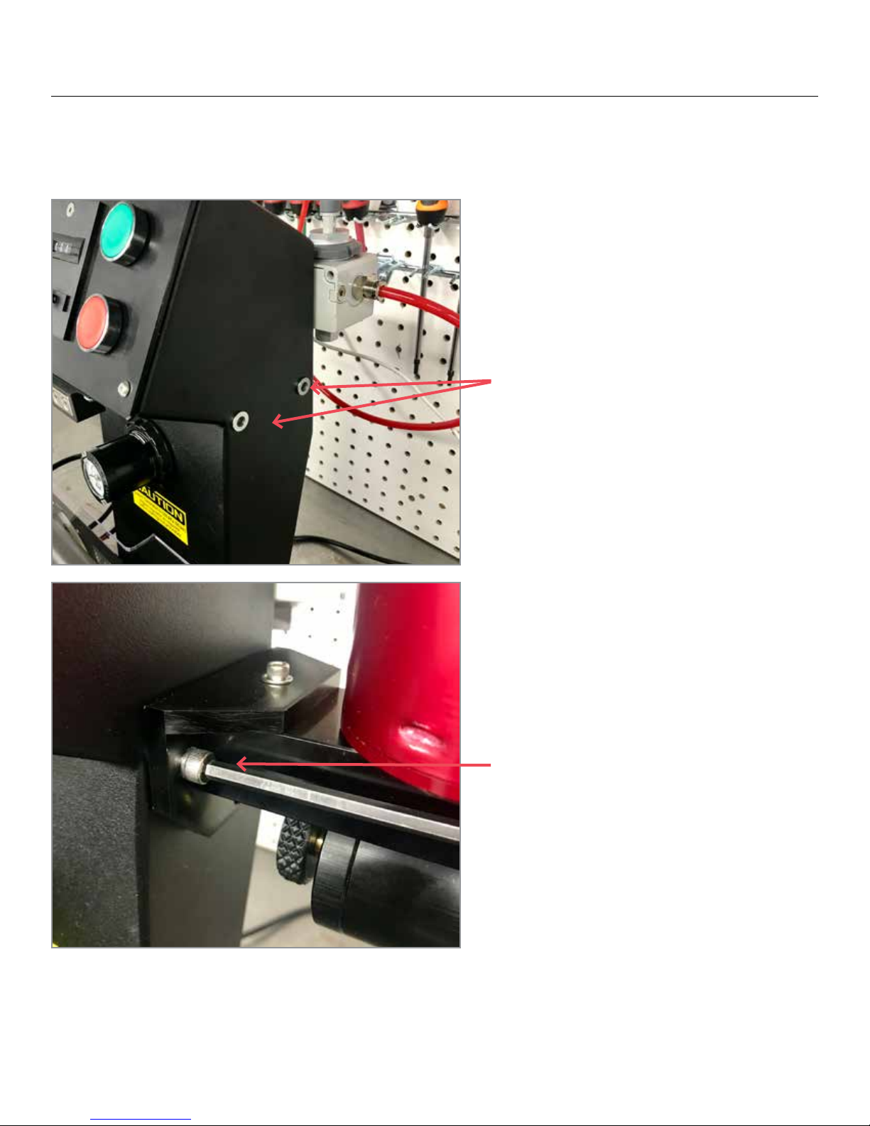
Installing MEK Reservoir
1. Locate the two (2) rivnuts for the reservoir
2. Mount the two (2) screws for the reservoir
assembly as shown using the 1/8” allen key.
Do not over tighten the screws as it is possible
to strip the rivnuts if too much force is
applied.
7
Page 8
UNPACKING & INSTALLATION
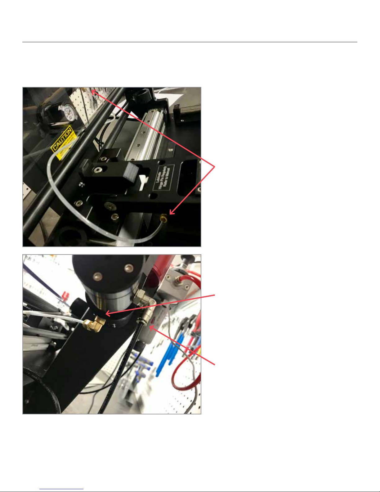
Installing MEK Reservoir
3. Connect the ow line coming from the
rubbing block to the ow valve located on the
bottom of the reservoir as shown
4. Tighten the tting by hand then use a
10mm wrench tighten an additional ¼ turn.
Excessive tightening may collapse the ferrell
and restrict the solvent ow.
5. Connect the air supply line from the
machine base to the back of the reservoir
assembly.
8
Page 9
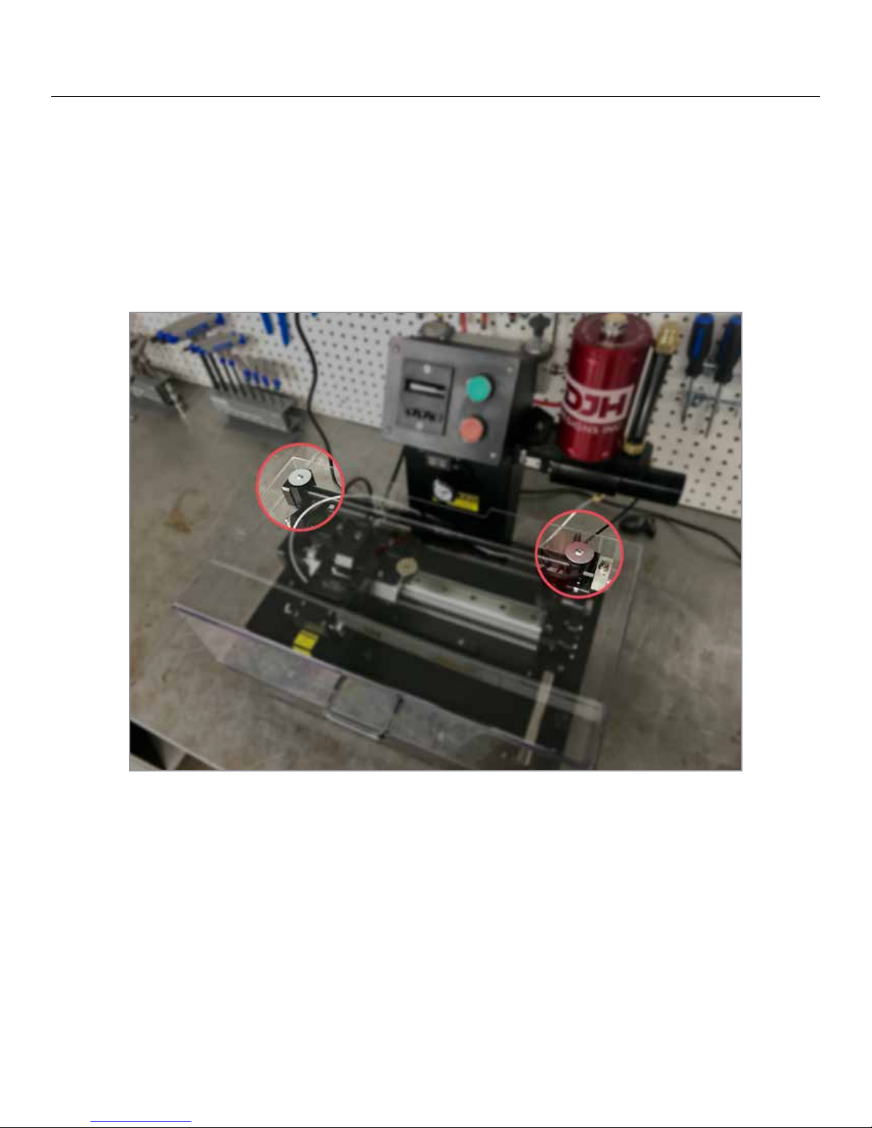
UNPACKING & INSTALLATION
Installing the Safety Cover
Align Front of cover to the front edge of the base plate and then align the holes in the cover to the holes in the
mounting blocks. You may have to rotate the mounting blocks to be in the correct orientation prior to sitting the
cover on the machine. Install the two mounting screws with the large diameter at washers supplied. All machines
are equipped with a cover interlock and the safety cover must be installed to operate the machine.
9
Page 10
UNPACKING & INSTALLATION
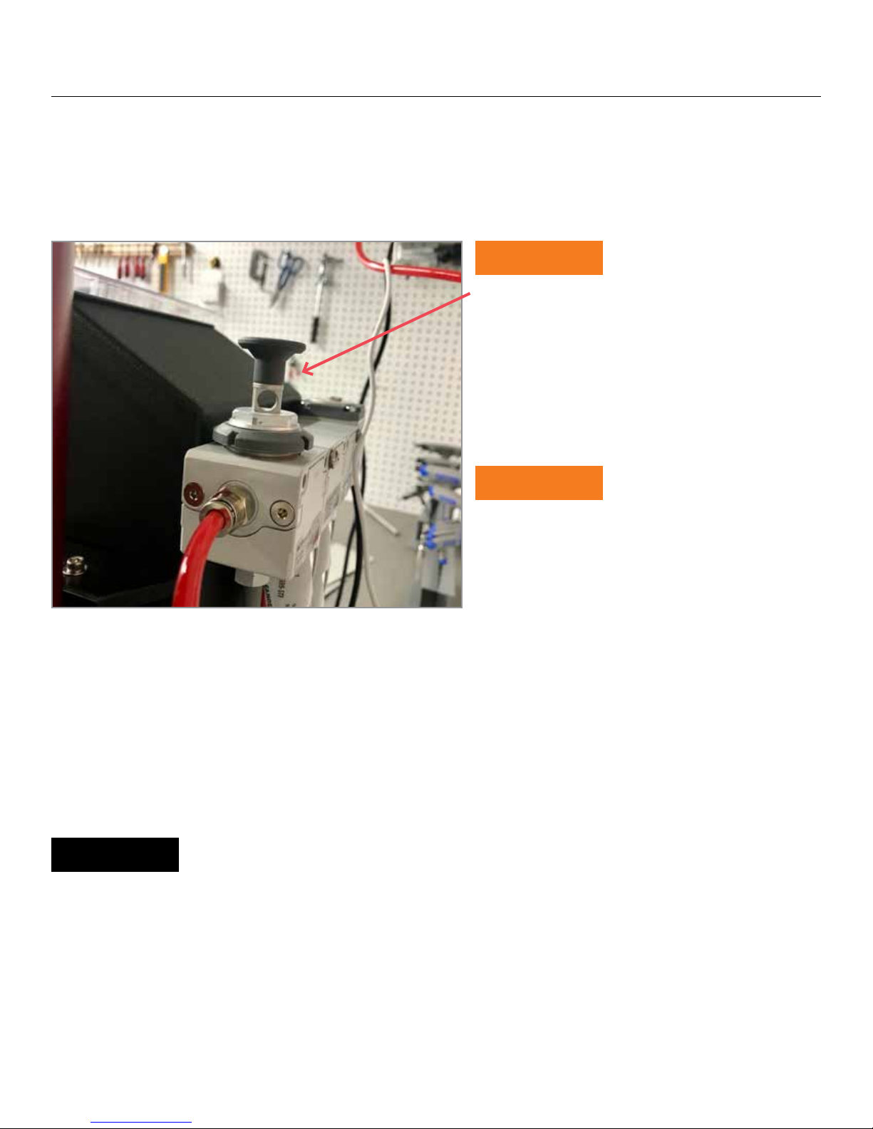
Air Supply Connection
e MEK Rub Test machine is supplied with a 2 stage air lter assembly pre-installed on the back of the unit,
bypassing or removal of these lters will void the machine warranty, if problems due to lters plugging up occur
the air supply problem should be addressed before continuing use of the machine.
CAUTION
Air Supply shuto, before connecting the airsupply
to the machine make sure that the machine airshut
o valve is in the closed position. (Pull up on the
handle to shuto air supply)
Connect the air supply to the inlet side of the lter
assembly
CAUTION
Clean, dry, oil free air only, any use of oiler’s or dirty
air supply will void your warranty. Use of synthetic
oils in the air supply can cause severe damage to
the internal valve seals and must be avoided
Once the air supply has been connected push the handle on the top of the lter assembly down to supply air the
machine pneumatics, check the pressure gauge (located in regulator) on the tower face on the front of the machine.
e correct operating pressure is 80 psi (550 Kpa). If the pressure is not correct adjust the regulator to the correct
pressure.
NOTE
Correct operating pressure is important to achieving accurate test results, incorrect pressure
will eect the number of strokes/min. Set pressure to 80 psi (550 Kpa) setting is done statically
do not try to adjust the pressure while the machine is running.
10
Page 11
UNPACKING & INSTALLATION
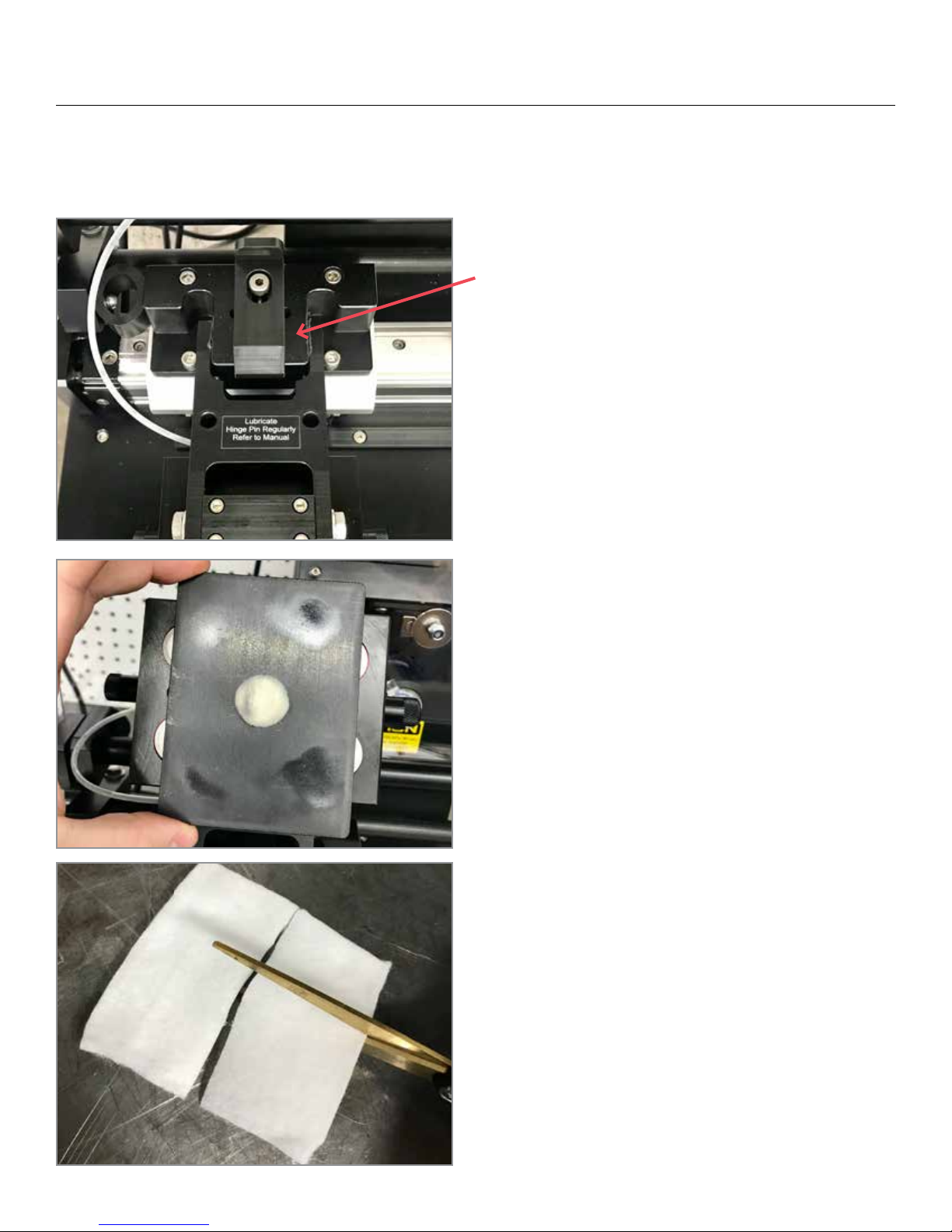
Replacing the Rubbing Pad
The MEK rub test machine is equipped with a safety
latch device, this latch will prevent the head from inadvertently falling back down onto the base plate if the
machine happens to be bumped or if the head was not
raised up fully to the over centre position of the head.
Raising the head requires no operator interaction with
the latch; the unit is spring loaded and will slide back as
the head is raised against it. Once the head is raised past
the latch point the latching device will snap back into
place the head is now in the up and locked position. To
lower the head, raise the head up fully if it is resting on
the latch and with your free hand depress the latch and
lower the head.
1. Rotate the holding plate 90° and li o. e plate is
magnetically held to the rubbing block.
2. Remove the old pad and discard
3. Cut the cotton pad into quarters and place the clean pad
(approximate size 1½ x 1¾), double ply, diagonally over
the plastic button, corners of the pad between the magnets.
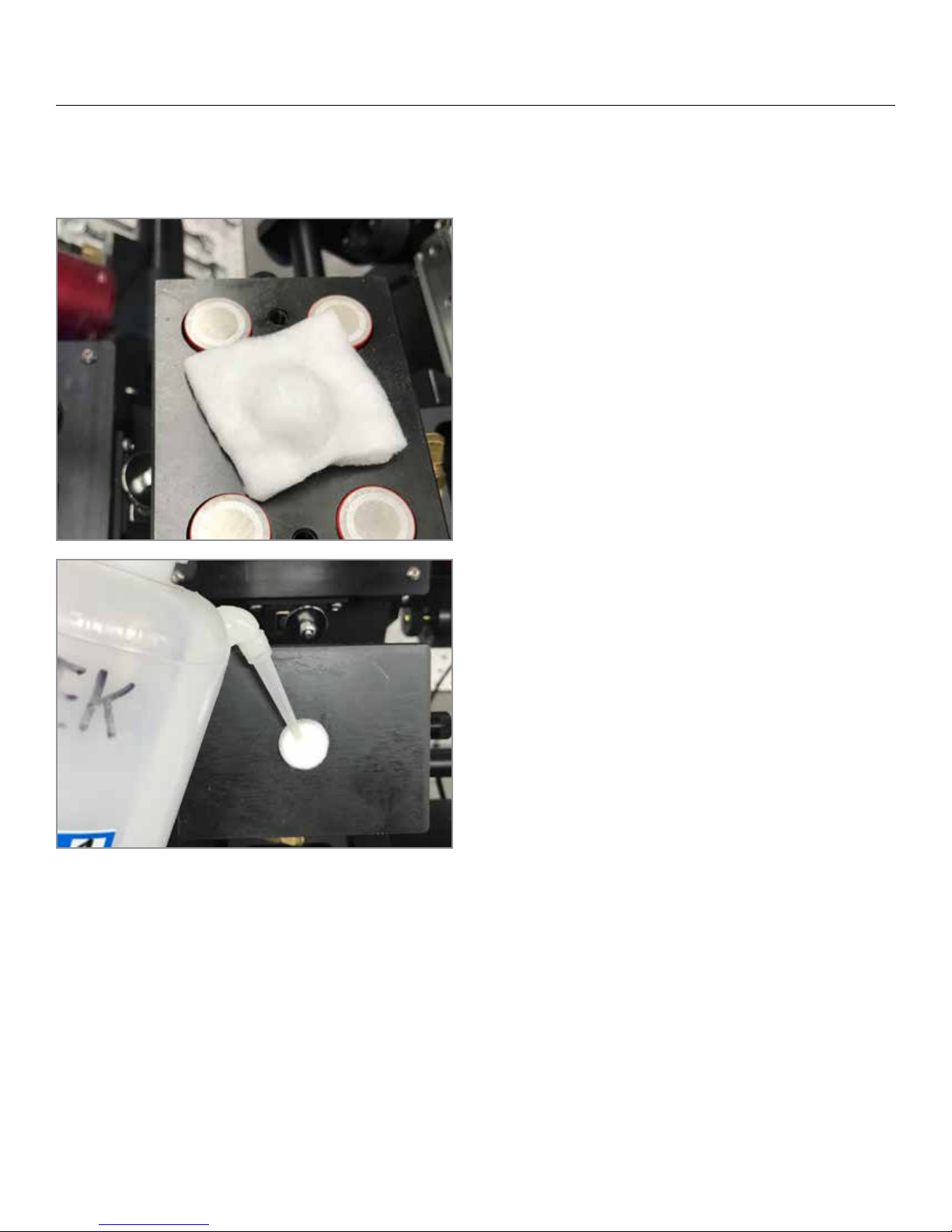
4. Re-attach the plate at 90° and rotate back into original
position
5. Wet the new pad with the MEK
11
Page 12
UNPACKING & INSTALLATION
Replacing the Rubbing Pad
4. Re-attach the plate at 90° and rotate back into original
position
5. Wet the new pad with the MEK
12
Page 13
UNPACKING & INSTALLATION
Filling the MEK Reservoir
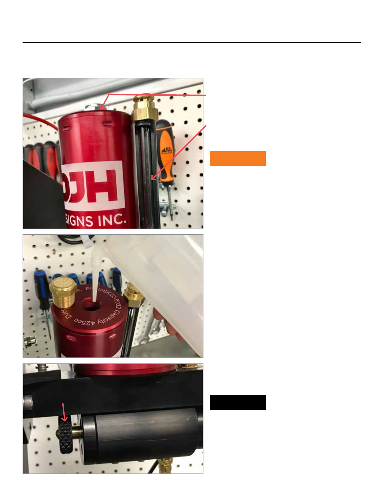
1. To ll the MEK reservoir, rst remove the ller
cap.
2. Use the Squeeze bottle provided to ll the
reservoir, approximately 425cc. e reservoir has a
site level so that you can see the level of MEK in the
reservoir at all times.
CAUTION
Do NOT try and pour MEK or any other solvent
from an open container, use only the squeeze bottle
provided or an equivalent type of container.
3. Adjusting the ow rate; the ow rate of the valve
has been preset at the factory, however you may
nd it necessary to adjust the ow rate to suit a
particular test or a dierent pad material type. e
2. Filling Reservoir
rate is adjusted by opening or closing the control
valve located on the bottom of the main valve body.
You only require enough MEK owing to keep the
sample wet if the MEK begins pooling rapidly then
cut down on the ow rate. If you are unable to
adjust the ow rate, the ow control valve metering
orice may be blocked with contaminants.
3. Adjust ow rate by rotating
NOTE
It is recommended that you lter the solvent prior
to lling the reservoir to prevent dirt and other
contaminations from blocking the small orice in
the metering valve.
13
Page 14
TESTING A PANEL
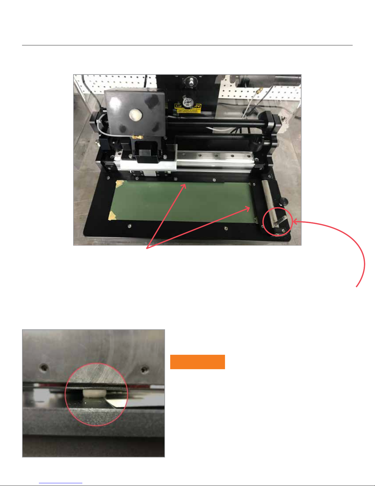
Minimum size 13cm (5”) x 30cm (12”) (unless equipped with variable stroke kit).
Place the panel on the test area, butt the right edge up against the locating pins under the panel holding clamp, and
slide the top edge against and under the stop bar. e stop bar is machined with a taper so if the panel has a bow
it will help to hold it at.
Turn the clamp lever Clock Wise to secure the panel. If the clamp rotates too far clock-wise (i.e. 3 O’ Clock
position, return it to the vertical position and turn the knurled knob a quarter turn and try again. Do not use
excessive force to clamp the panel), Turn the lever Clock-wise just tight enough to secure the panel.
CAUTION
Do not use a panel shorter than 30cm (12”), if the panel is too
short and the nozzle is allowed to ride over the edge of the
panel as shown, it will damage the solvent nozzle.
An optional Variable Stroke Kit is available for testing short
panels.
14
Page 15
OPTIONAL VARIABLE STROKE KIT
e Variable Stroke Kit is an add kit that allows for the use of non standard size panels ranging in length from 9cm
(3.5”) to 30cm (12”).
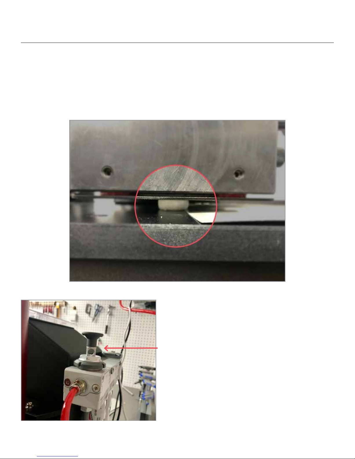
Adjusting the stroke length; when testing non standard length panels it will be necessary to adjust the stroke length
so that the nozzle cannot ride over the edge of the panel as shown below and cause damage to the nozzle.
1. Turn o the air supply to the machine by pulling up on the
shuto valve located on the top of the lter assembly.
15
Page 16
OPTIONAL VARIABLE STROKE KIT
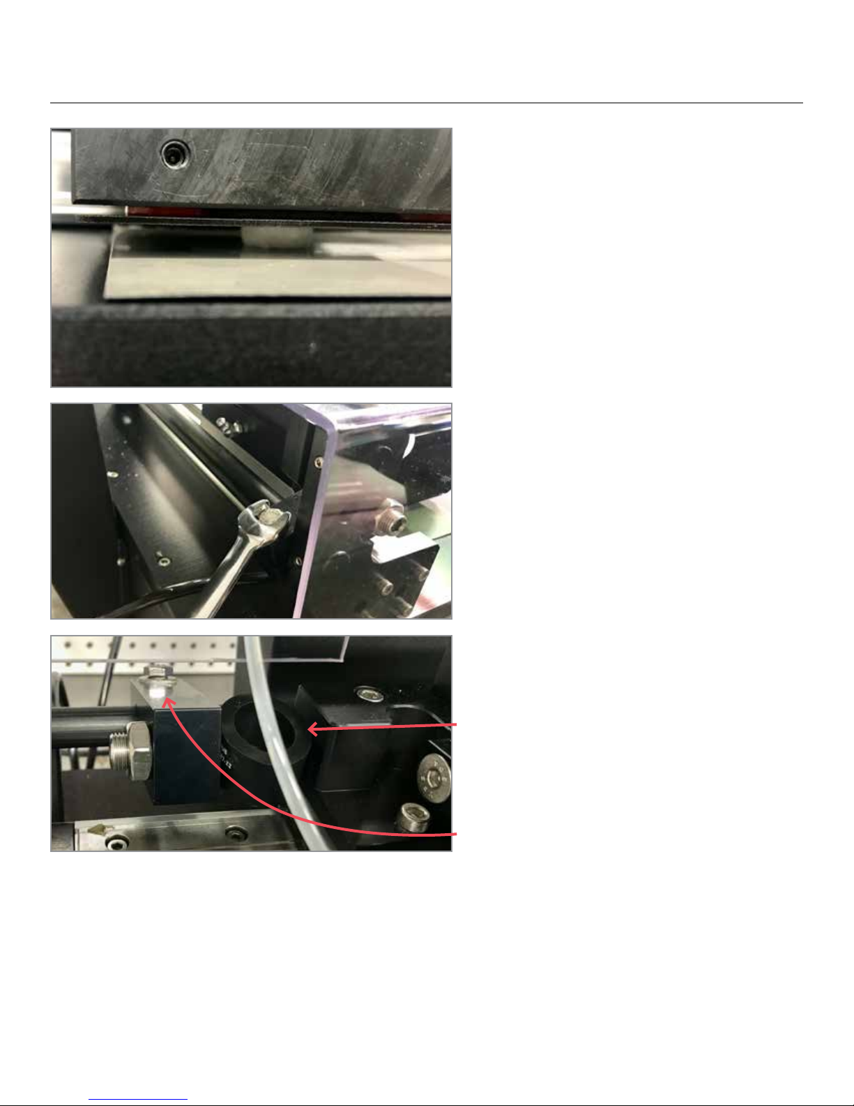
2. Move the rubbing head by hand until the nozzle
is positioned completely on the test panel close to
the le edge as shown.
3. Locate the bolt on the stop block at the back le
and loosen with a ⁄” wrench.
4. Move the bumper until it comes in contact with
the head.
5. When running the machine, the absorption
of the bumper is approximately 1cm (0.39”), so
take that into consideration when setting up your
variable sample.
6. Fasten the bolt on the stop block to tighten into
place.
16
Page 17
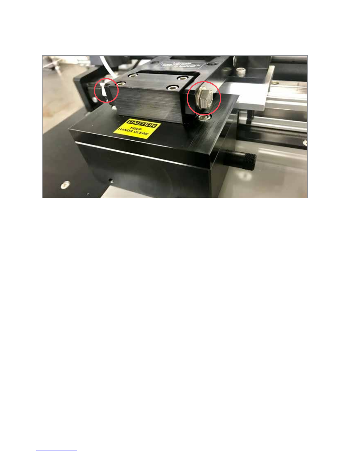
ADJUSTING THE RUBBING BLOCK
Adjustment to the rubbing block is normally only required if you want to change to running much thicker test
panels. However, periodical adjustments to the rubbing block alignment may be required if the head has been
dropped onto the sample to hard, or has been shied for any reason.
To adjust the rubbing block, remove the MEK Pad (see page 10) and lower the head down onto the sample you
want to test. Looking from the side of the block you can see that the button does not sit squarely on the sample.
Loosen the 2 bolts that hold the block to the “H” arm, rotate the block forward and back to sit it squarely on the
sample. Retighten the bolts, replace the pad and you are ready to begin your test.
17
Page 18
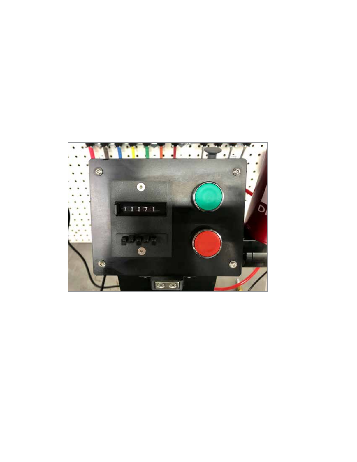
RUNNING THE MACHINE
Setting the Number of Strokes
Preset the number of strokes (forward and back, a “double rub” counts as one stroke) press the button to the le of
the digital counter display and hold it down. Press the buttons under each digit (ones, tens, hundreds, thousands)
to select the number of strokes on the display. e counter will count down as the machine runs its test. To reset
the counter to your original preset number of strokes simply press the button to le of the display again, only this
time just press and release the button, the counter will return to the preset number of strokes.
18
Page 19
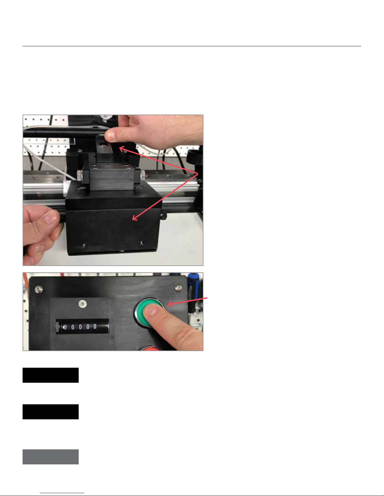
RUNNING THE MACHINE
Running the Rub Test
Please make sure that you do the following before running MEK Rub Testing machine:
• Filling the MEK Reservoir (page 11)
• Testing a panel (page 12)
1. Lower the block onto the panel (push unlock
lever to lower the block)
2. Set number of double rubs (see previous page)
NOTE
NOTE
TIP
3. Press the start (Green) button. On completion of
the preset number of strokes the machine will stop
automatically.
You can stop and start at any point during the count down with no interruption to the cycle
total (i.e. the stop button is depressed during a cycle the counter stops at 25 strokes remaining,
pressing the start button will begin the count down from that point, 25 remaining strokes).
Dierent pad materials will aect your test results, if you are trying to correlate your results
with another unit it is important to make sure that you are both using the same pad material.
e cotton pads provided with the machine are ASTM compliant and can be purchased
through DJH (PN: 1963)
To establish the required number of strokes that is acceptable to your standards, run a known
panel by your hand method, and run a parallel test on the same panel with the machine. Stop
the machine when the results appear similar. is will be your new test requirement.
19
Page 20
MAINTENANCE
Be sure to check the coalescing air lter and replace as required.
NOTE
Check the secondary lter assembly and service as required.
If you notice a continued drop in air pressure to the machine, it is a good indication that the
coalescing lter element requires replacement.
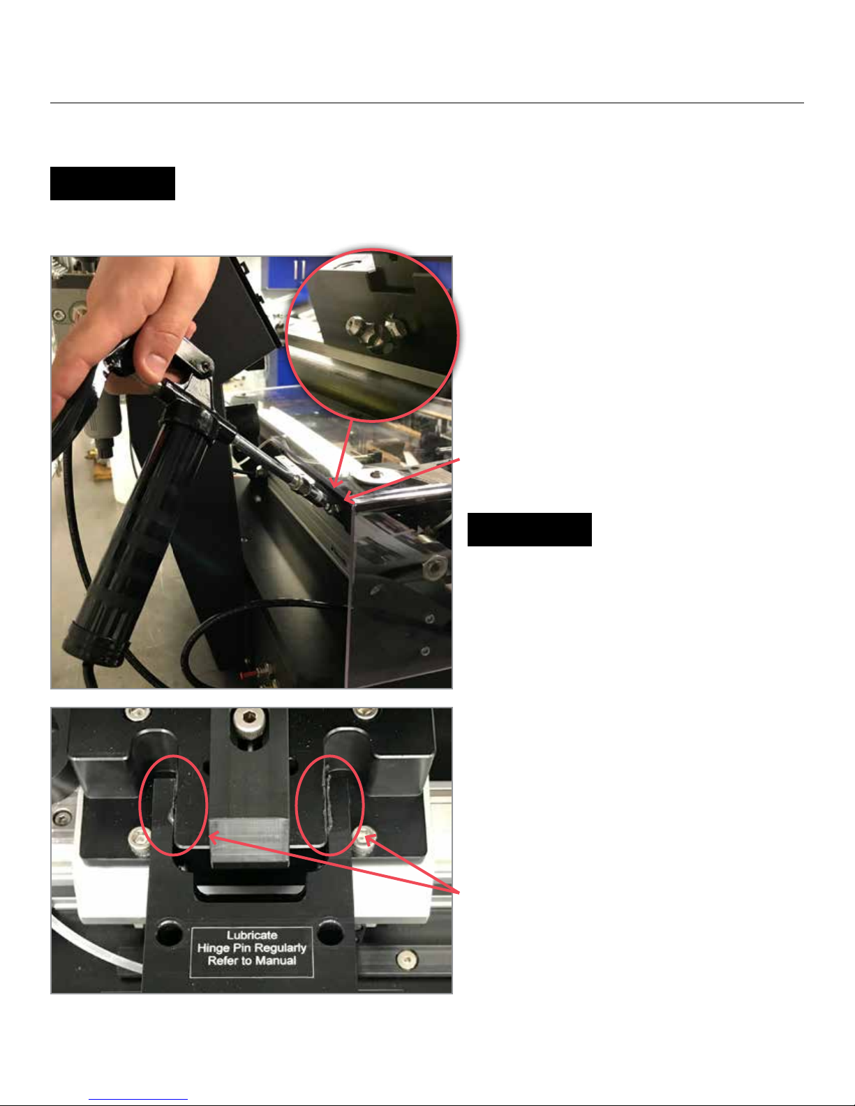
Lubricating the rubbing block hinge pin
Use the supplied grease gun and add grease until
you see the overow from both ends of the pin as
shown in the image.
NOTE
Hinge pin and slide must be lubricated weekly.
Hinge pin; watch for over ow from both ends
20
Page 21
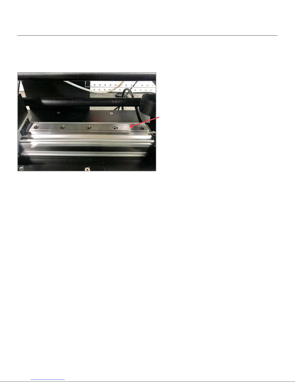
MAINTENANCE
Be sure to lubricate the slide rail with 2 to 3 drops
of instrument oil weekly
21
Page 22

MACHINE SPECIFICATIONS
Weight of machine 28.3 kg (62.5 lbs)
MEK reservoir capacity 425 cc.
Mass of Rubbing Block 3kg (6.8 lbs) - Standard
Stroke Length 20.3cm (8”)
Number of strokes/min (Double Rub)* 70
Operational air pressure 550 KPa (80 psi)
Max air supply pressure 965 KPa (140 psi)
Air consumption @ operational pressure 66.54 L/min @ 345 KPa (50 psi)
Minimum Flexible air line supply size ¼” I.D.
Air inlet connection at filter ¼” NPT
Cotton Pad size 1½ x 1¾, 2 ply
Counter max number of strokes 99999
Air supply Clean and dry (non condensing)
Dimensions (Width Depth Height) 45.7cm x 48.3cm x 48.3mm (18” x 19” x 19”)
Test panel size 12.7cm x 30.5cm (5” x 12”)
Panel thickness max** 3.2 mm (1/8”)
Electrical Requirements None (all pneumatic system)
Compatible Solvents MEK, Acetyl Acetone, Acetone, Acetylene,
Isopropyl Alcohol, Methanol
* As per ASTM standard
** icker panels can be run, please contact DJH Designs for more information
CAUTION
Never use corrosive solutions. is machine is not designed to use anything other than
what is stated above under “compatible solvents”.
22
Page 23

WHERE TO FIND HELP
Our Commitment
DJH Designs stands behind the product you have purchased. Depending on how you purchase and use your
equipment, the best source of support is either from, DJH Designs, or your own organization. Your warranty
statement is included in this chapter. Please read it carefully and retain it for your records.
Help From Your Organization
If your organization has a number of MEK Rub Test Machines, the best source of assistance may be within your
own company. Many companies designate central support personnel to help when you have problems with using
your system (i.e. long time, experienced system user’s).
24 Hour Online Help from DJH Designs Website
DJH Designs can also be reached 24 hrs a day 7 days a week on our website. Our products and support page can
provide you with answers to most problems. You can also E-mail your request to several E-mail accounts. See
Service and support page, second last page in this manual for web address and E-mail accounts.
Help From DJH Designs Customer Support Center
If you are unable to solve a problem, or you require information about your system or other products, DJH Designs
would be happy to provide you with the support / information you require. Support is available from 7 a.m. until
6 p.m.; (Eastern Time) Monday to Friday.
Call (905) 825-2750
DJH Designs Technical Support E-mail Address: [email protected]
DJH Designs Maintenance Agreements
DJH Designs is currently developing several types of maintenance agreements that will meet a wide range of
support needs.
Service Agreements
• Priority On-Site Service is being designed for production critical applications, giving you 24 hour service
response to your site for calls made during normal DJH Designs business hours.
• Next Day On-Site Service will provide on-site support within 72 hours following your service request. Extended
coverage hours and extended travel beyond DJH Designs designated service zones will be available for additional
charges on most on-site service agreements.
• Yearly On-Site Service Agreement will provide economical, scheduled on-site coverage. is service will provide
annual scheduled maintenance and repair visits to your location.
** Some Service agreements may not be available in your location, contact DJH Designs for specic information **
23
Page 24

ONE YEAR LIMITED WARRANTY
DJH Designs warranties its products against defects in materials and workmanship for a period of one year from
the date of purchase. DJH Designs will at its option, either repair or replace products which prove to be defective.
Exclusions
e warranty on your DJH Designs MEK Rub Test Machine will not apply to defects or damages resulting from;
• Improper or inadequate maintenance by the customer.
• Unauthorized modication or misuse.
• Operation outside of the environmental specications of the equipment.
• Improper site preparation or maintenance.
• Contaminated air supply (moisture, oil, debris)
e warranty period begins either on the date of delivery, or when the purchase price includes installation by DJH
Designs, on the date of installation.
Warranty Limitations
e warranty set forth above is exclusive and no other warranty, whether written or oral, is expressed or implied.
DJH Designs specically disclaims the implied warranties of merchantability and tness for a purpose.
Some states or provinces do not allow limitation on how long an implied warranty lasts, so the above limitation or
exclusion may not apply to you. However, any implied warranty of merchantability or tness is limited to the one
year duration of this written warranty.
Obtaining Service during the Warranty Period
Should your hardware fail during the warranty period, send your product to DJH Designs or you may also request
service from the component manufacturer or one of their authorized agents. To locate a service center or to receive
information about obtaining service, please see the service and support phone list on the next page
Obtaining Service aer the Warranty Period
If your hardware fails aer the warranty period, contact DJH Designs to obtain service.
When sending equipment to DJH Designs, follow the repacking guidelines listed below. Also, complete and enclose
a copy of the service information form at the end of this chapter. Insuring the equipment for shipment is highly
recommended.
CAUTION
Shipping damages as a result of inadequate packaging is the customer’s responsibility. Use the
original packing materials whenever possible.
24
Page 25
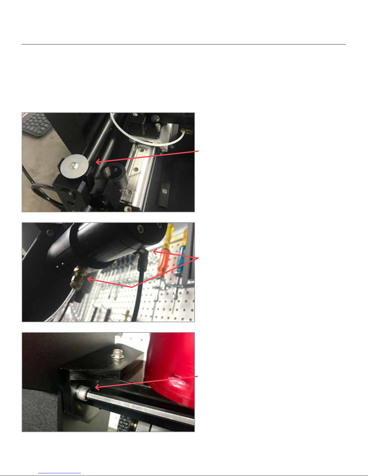
REPACKAGING GUIDELINES
Use the original packing materials whenever possible. If you have already disposed of your packing material,
please take care in making sure that the equipment is well packaged and protected. You can also request the proper
shipping container from DJH Designs. (Container cost and shipping charges will apply)
Instructions for packing MEK Rub Test Machine in ISPM15 compliant crate.
1. Safety shield must not be installed when
repackaging. Remove safety shield and place
washer/screws back into the inserts safely as shown.
2. Disconnect reservoire & air supply lines prior to
packaging.
3. Disconnect & uninstall MEK reservoire by
removing the two screws. Once removed, reinstall
screws to secure them and tighten them slightly.
25
Page 26
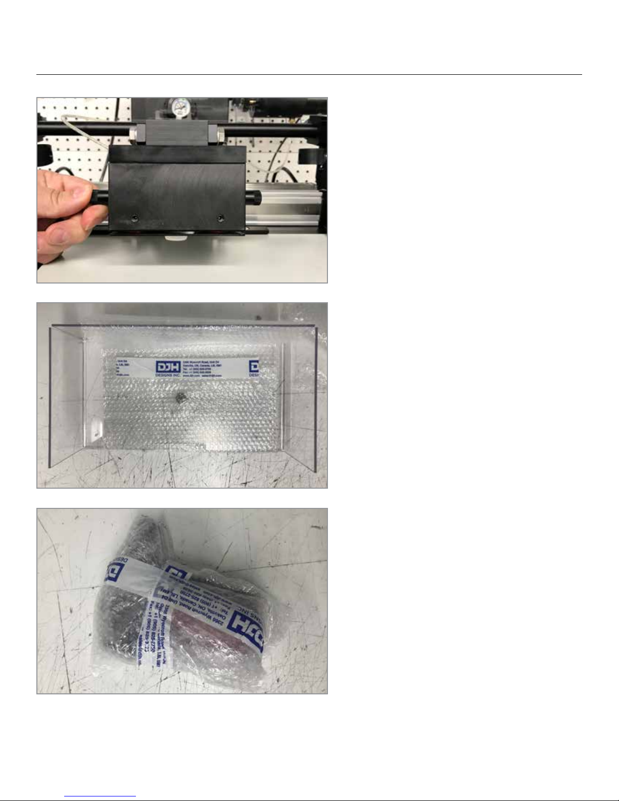
REPACKAGING GUIDELINES
4. Ensure that the rubbing block is in the down
position.
5. Wrap safety shield in a protective padding as
shown.
6. Wrap MEK reservoire in protective padding as
shown and place into the provided box.
Failure to properly secure the machine to the base
and to the crate structure may result in damage to
the machine.
26
Page 27
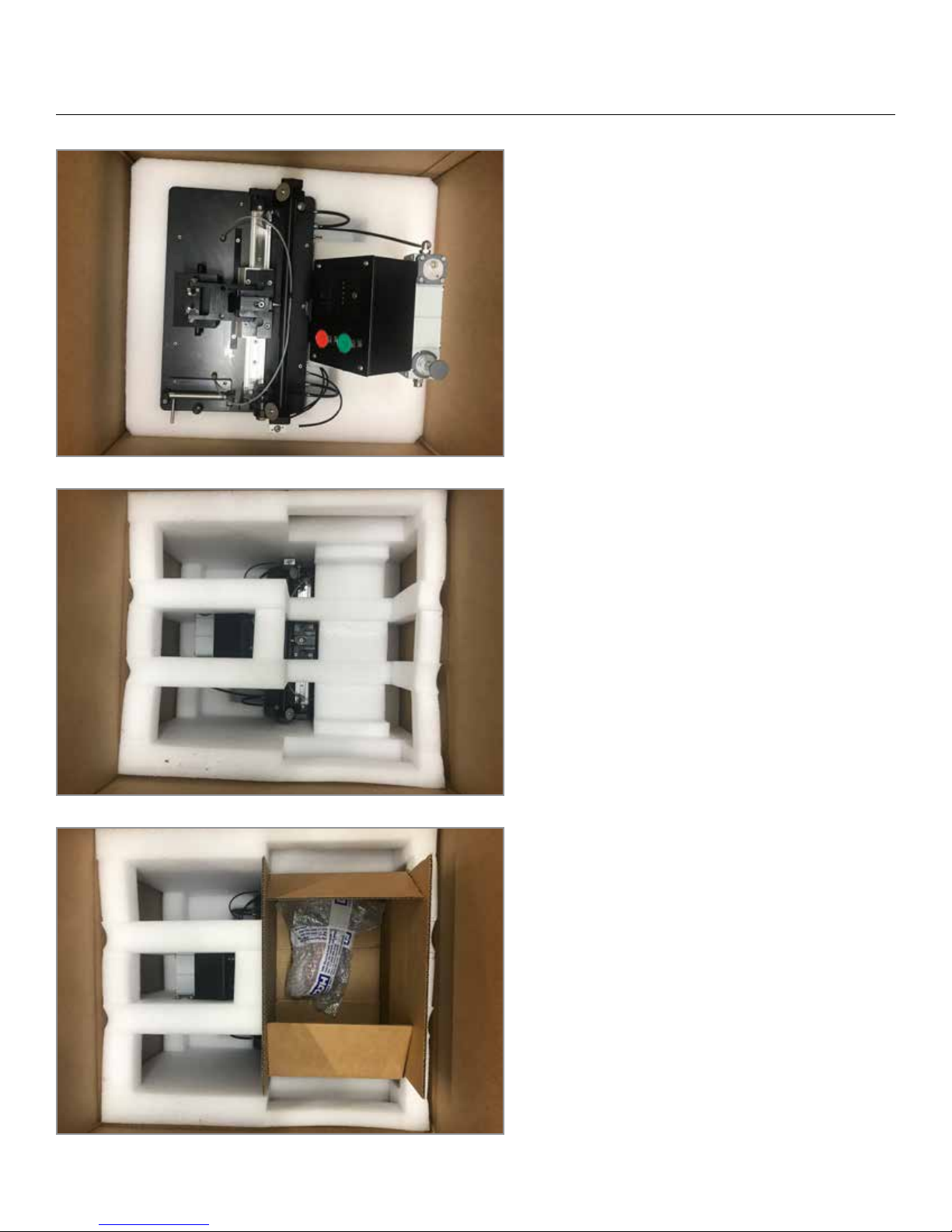
REPACKAGING GUIDELINES
4. Place MEK machine base into foam insert as
shown. Failure to properly secure the machine to
the base and to the crate structure may result in
damage to the machine.
5. Place top layer of foam on top of machine. is
will only t one way.
6. Place box containing packaged MEK reservoir
as shown.
27
Page 28
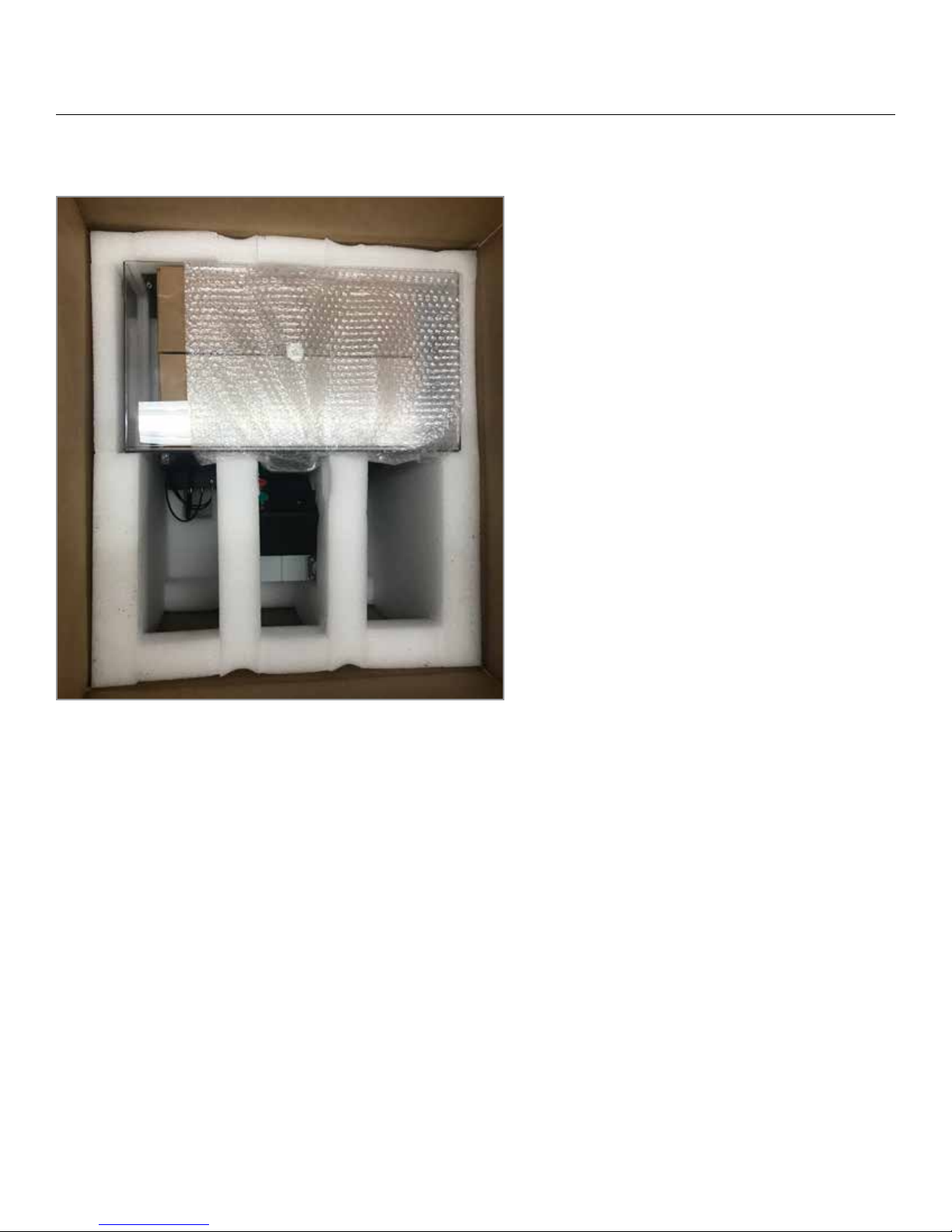
REPACKAGING GUIDELINES
7. Place the protected safety cover overtop of the
box containing the MEK reservoire so that it sits
ush on top.
28
Page 29

SERVICE & SUPPORT
DJH Designs telephone (905) 825-2750
(800) 616-8818 (Canada/US)
DJH Designs fax (905) 825-3628
DJH Designs technical support E-Mail address [email protected]
Question or Comments can be directed to: [email protected]
DJH Designs web site www.djh.com
For service, please visit our website or contact [email protected].
29
Page 30
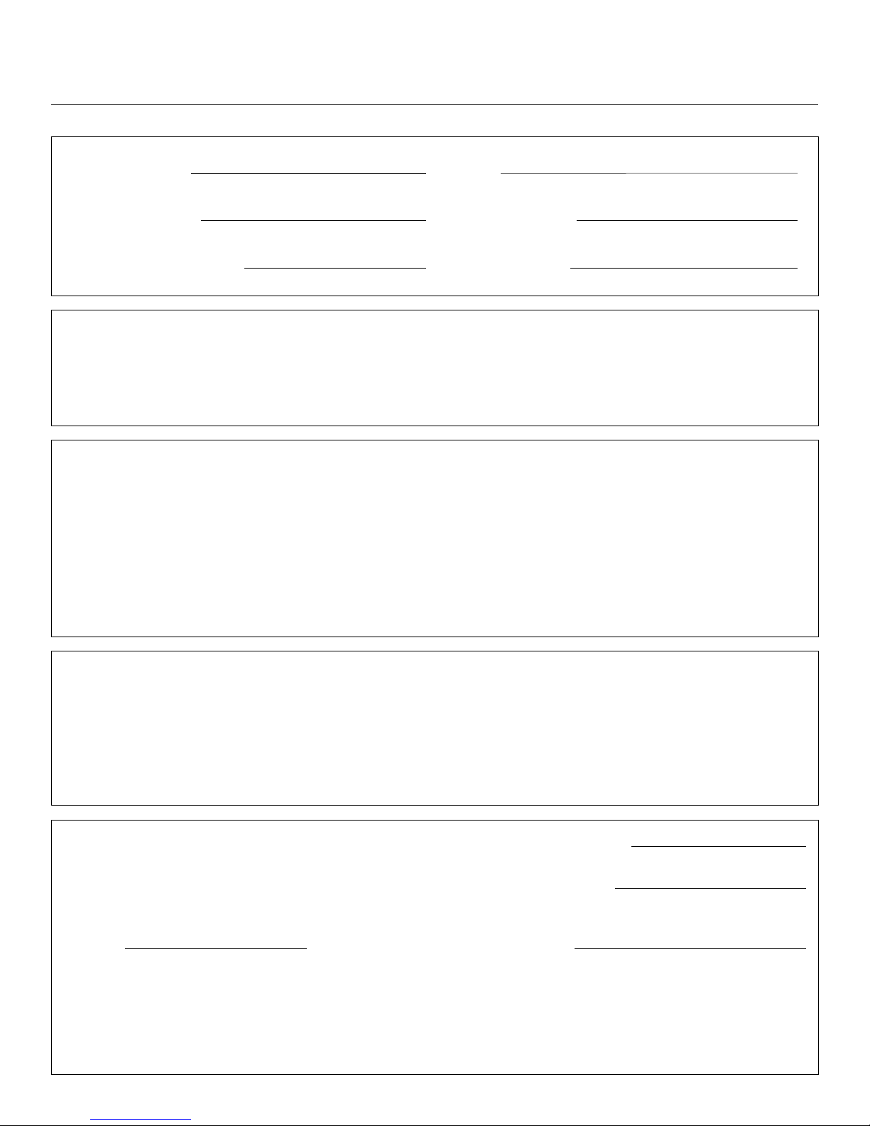
SERVICE REQUEST FORM
Company Name: Date:
Person to Contact: Phone Number:
Machine Purchase Date: Serial Number:
Return shipping address: Special shipping instructions:
What needs to be done? Describe the conditions of the failure.
(What was the failure? What where you doing when the failure occurred?)
If the failure is intermediate, how much time occurs between failures?
Additional comments:
Except in the instance of warranty service, a Purchase order number:
purchase order and/or authorized signature
must accompany any request for service. Authorized Signature:
Phone: Billing Address:
Special billing instructions:
30
 Loading...