

DIZIC DZUSB01 User Manual
Introduction
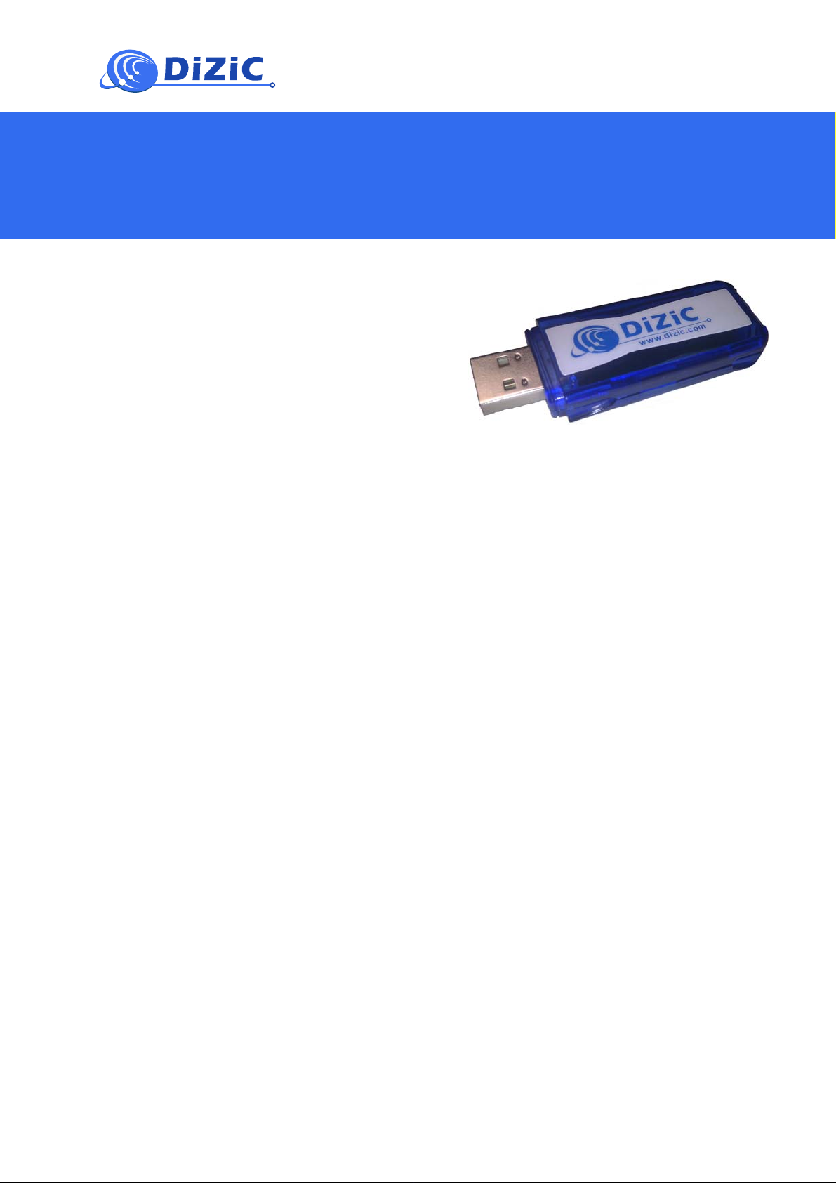
The DiZiC DZ-ZB-USB Dongle allows you to quickly
add wireless networking capabilities to your Laptop
or PC. Plug the Dongle to a USB port and get instant
access to Zigbee or 802.15.4 proprietary networks
management. This tool let you easily configure
diagnostic and monitor local networks.
Additionally application code can be developed,
tested and updated any time through the pre-
installed boot loader.
Key Features
• 2.4 GHz CSS transceiver
• 32-bit ARM® Cortex-M3 processor
• 128 kB flash, 8kB RAM memory
• AES128 encryption accelerator
• Two configurable LEDs
Upgradable Software
• Re-programming through USB
RF Performances
• Rx sensitivity (- 100 dBm)
• Tx output power level (+8 dBm)
DZ-ZB-DMB02 Evaluation Board
User’s Manual
USB Dongle
Target Applications
• Smart Energy
• Building automation and control (HVAC)
• Home automation and control
• Security and monitoring
• AMR/AMI
• Medical
• General ZigBee wireless sensor networking
• Wireless hand-held terminals
• Industry telemetry /automatic data collection
• Temperature and humidity control systems

Table of Content
Notice: ........................................................................................................................................ 3
FCC Warning: ............................................................................................................................ 3
IC Warning: ................................................................................................................................ 3
1. Getting Started .................................................................................................................. 4
1.1. Connecting the Board .................................................................................................. 4
1.2. Application GUI based testing .................................................................................... 5
1.2.1. Evaluation board control interface ........................................................................... 5
1.2.2. Module basic setups ................................................................................................. 6
1.2.3. Module transmitter and receiver tests ...................................................................... 6
1.3. Windows Terminal based testing ................................................................................ 7
1.3.1. Transmitter Test ....................................................................................................... 7
1.3.2. Receiver Test ........................................................................................................... 8
APPENDIX ................................................................................................................................ 9
A. Software Configuration .................................................................................................... 9
A.1. Installing FTDI USB Device Driver ............................................................................ 9
A.2. About Tera Term ......................................................................................................... 9
A.2.1. Configuring Tera Term ............................................................................................ 9
A.3. Binary file re-programming ......................................................................................... 9
Copyrights ................................................................................................................................ 10
Document Information ............................................................................................................. 10
Revision History ....................................................................................................................... 10
About DiZiC ............................................................................................................................. 10
Table of Figures
Fig. 1 Typical test and development setup ................................................................................. 4
Fig. 2 Main dialog box evaluation board selection .................................................................... 5
Fig. 3 Module RF selection control panel .................................................................................. 5
Fig. 4 RF setup control panel options for a standard module .................................................... 6
Fig. 5 RF setup control panel options for a +20dBm module .................................................... 6
Fig. 6 Transmitter and receiver control panel section ................................................................ 6
Fig. 7 Tera Term successful connection to the evaluation board ............................................... 7
March 2011 Doc ID:DZ UM-USB01 preview rev0.1
© 2011 DiZiC Co. Ltd. Subject t o change wi thout notice.
2

Notice:
This equipment has been tested and found to comply with the limits for a Class B digital device,
pursuant to Part 15 of the FCC Rules. These limits are designed to provide reasonable protection
against harmful interference in a residential installation. This equipment generates uses and can
radiate radio frequency energy and, if not installed and used in accordance with the instructions, may
cause harmful interference to radio communications. However, there is no guarantee that interference
will not occur in a particular installation. If this equipment does cause harmful interference to radio or
television reception, which can be determined by turning the equipment off and on, the user is
encouraged to try to correct the interference by one or more of the following measures:
-- Reorient or relocate the receiving antenna.
-- Increase the separation between the equipment and receiver.
-- Connect the equipment into an outlet on a circuit different from that to which the receiver is
connected.
-- Consult the dealer or an experienced radio/TV technician for help
FCC Warning:
This equipment complies with FCC and IC radiation exposure limits set forth for an uncontrolled
environment. End users must follow the specific operating instructions for satisfying RF exposure
compliance.
This transmitter must not be co-located or operating in conjunction with any other antenna or
transmitter.
The USB Dongle must be installed and operated at a distance no closer then 8 inches (20 cm) from
the user.
FCC: 15.21 “Changes or modifications are not expressly approved by the manufacturer could void the
user's authority to operate the equipment.”
This device complies with part 15 of the FCC Rules. Operation is subject to the following two
conditions: (1)This device may not cause harmful interference, and (2) this device must accept any
interference received, including interference that may cause undesired operation
IC Warning:
This device complies with Industry Canada license-exempt RSS standard(s). Operation is subject to
the following two conditions: (1) this device may not cause interference, and (2) this device must
accept any interference, including interference that may cause undesired operation of the device."
Le présent appareil est conforme aux CNR d'Industrie Canada applicables aux appareils radio
exempts de licence. L'exploitation est autorisée aux deux conditions suivantes : (1) l'appareil ne doit
pas produire de brouillage, et (2) l'utilisateur de l'appareil doit accepter tout brouillage radioélectrique
subi, même si le brouillage est susceptible d'en compromettre le fonctionnement."
March 2011 Doc ID:DZ UM-USB01 preview rev0.1
© 2011 DiZiC Co. Ltd. Subject t o change wi thout notice.
3
 Loading...