

Dixon Marking Tools ZTR 4421, ZTR 4422 User Manual

DIXON INDUSTRIES, INC
A BLOUNT COMPANY
AIRPORT INDUSTRIAL PARK
COFFEYVILLE KS 67337 0945
PO BOX 1569
316 251 2000
FAX 316 251 4117
TECHNICAL DATA BROCHURE
ZTR 4421 & 4422
IMPORTANT: READ OPERATOR'S MANUAL BEFORE OPERATING OR MAKING ADJUSTMENTS
DELUXE SEAT ADJUSTMENT:
Raise upper body to fully open position by lifting on arm rest and seat back. Loosen seat
adjustment knobs under seat frame. Slide seat to desired setting and fully tighten seat
adjustment knobs.
Caution: DO NOT
Page 1 of 13
Operate mower unless seat adjustment knobs are fully tightened.
REMOVING THE BODY:

1. Both the 4421 & 4422 use a two piece body. The upper body can be raised up and back, and
also tilted forward to expose the transaxle.
2. To remove upper body, lift up and fold forward. Disconnect throttle cable P/N 4679 from
engine. Disconnect wiring harness by simply pulling plug apart. Then clip wire ties so
harness
mounting pin P/N 1460. Then hold upper body and remove pin P/N 1460.
is loose from seat bracket. Next remove cotter key P/N 3052 from upper body
3. Reverse above procedure to reinstall.
ADJUSTMENT OF MOWER DECK DRIVE BELT:
No adjustment necessary! The spring loaded idler pulley maintains proper tension throughout belt
life.
REMOVING THE MOWER BLADE:
1. Secure mower blade P/N 8688 from turning.
2. Observe blade position when removing.
3. Remove blade bolt P/N 3268, and blade washer P/N 6260.
4. To reinstall, reverse above procedure. Tighten blade bolts to 60 ft. Ibs. of torque.
WARNING: Sharp edges on blade can cause injury! Caution should be exercised when
required on the blade.
service is
REMOVING THE MOWER DECK:
1. Remove mower deck drive belt P/N 6111 by pulling idler pulley P/N 1687 away from belt and
remove belt from the rear pulley.
2. Remove the two clevis pins P/N 3072 from the L-rods at rear of deck and slide free from slots.
3. Remove the clevis pin P/N 3072 from the lift linkage at the front of deck.
4. Remove cotter pin from shaft P/N 1332 located at front of mower deck on slide plates
at battery box. Slide shaft free.
5. Raise front of mower and roll it free of mower deck assembly.
6. To install deck, reverse above procedure.
welded
Page 2 of 13

MOWER BLADE OPERATION:
1. To start mower blades, pull up slightly on blade drive switch handle and move it forward to
the "ON" position.
2. To stop mower blades, move switch handle to the "OFF" position.
SAFETY CHECKS
IMPORTANT - PERFORM SAFETY CHECKS AFTER MAKING ANY REPAIRS OR ADJUSTMENTS
1. After reassembly, while seated on mower, attempt to start engine with mower deck engaged.
Engine should not start. If engine does start, return the mower to an Au thorized Dixon dealer for
adjustment or repair.
2. Disengage mower deck and start engine. With the operator in the normal seated position,
engage mower deck and remove weight from seat. The engine should stop. If the engine does
not stop when operator ri ses from seat, return the mower to an Authorized Dixon dealer for
adjustment or repair.
3. Engage, then disengage mower blade in each cutting height. Insure that blade disengages and
comes to a stop within (5) seconds in each height position. If blade do es not disengage
properly, contact your Authorized Dixon dealer.
CAUTION: DO NOT OPERATE MOWER IF ANY SAFETY FEATURE IS NOT FUNCTIONING CORRECTLY
Parking Brake Adjustment:
1. Adjustment points are located at rear of transaxle on each side. Remove roll pins from swivel
fitting P/N 2172. Turn swivel fitting on brake rod P/N 5100 in, to tighten. Just enough to prevent
brake from slipping when engaged.
2. Reinstall roll pin.
CAUTION:
. Page 3 of 13
Over tightening may cause premature wear on brake band P/N 5085.
THE FOLLOWING INSTRUCTIONS REFER TO 42" MOWER DECKS:
Page 4 of 13
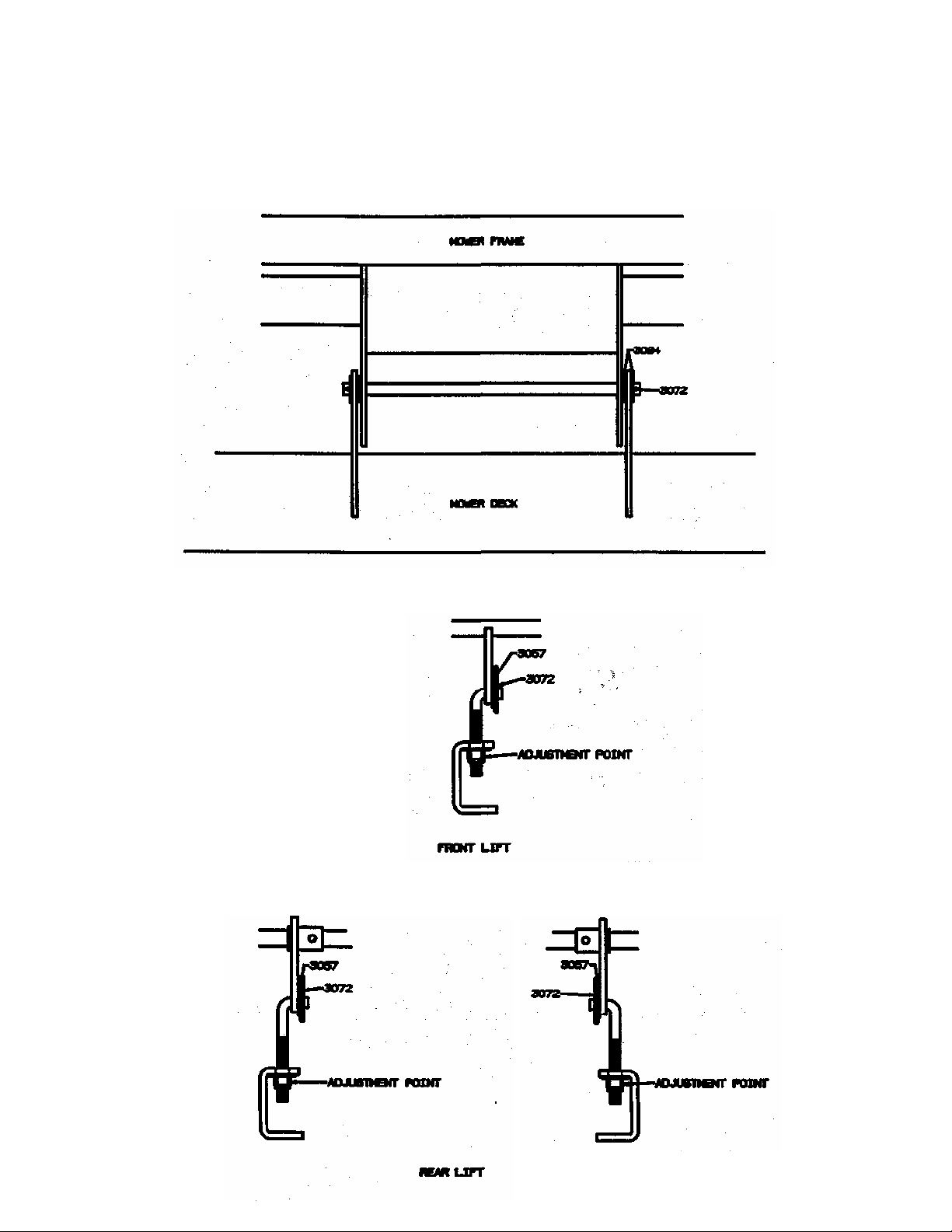
INSTALLATION:
1. Position mower deck assembly under frame, raise front of mower deck assembly enough to
allow cross shaft P/N 1332 to slide through frame guides and mower deck guides. Install (2)
washers P/N 3094 and (1) hair pin cotter P/N 3072 on each end of the cross shaft.
2. Attach short L-rod P/N 1355 to lift arm as shown in drawing.
3. Attach long L-rod P/N 1409 to rear lift arms as shown in drawing.
 Loading...