

Dixon N20W Service Manual
20" LCD Color Monitor Dixon N20W
1
Service
Service
Service
Horizontal Frequency
31 kHz-82 kHz
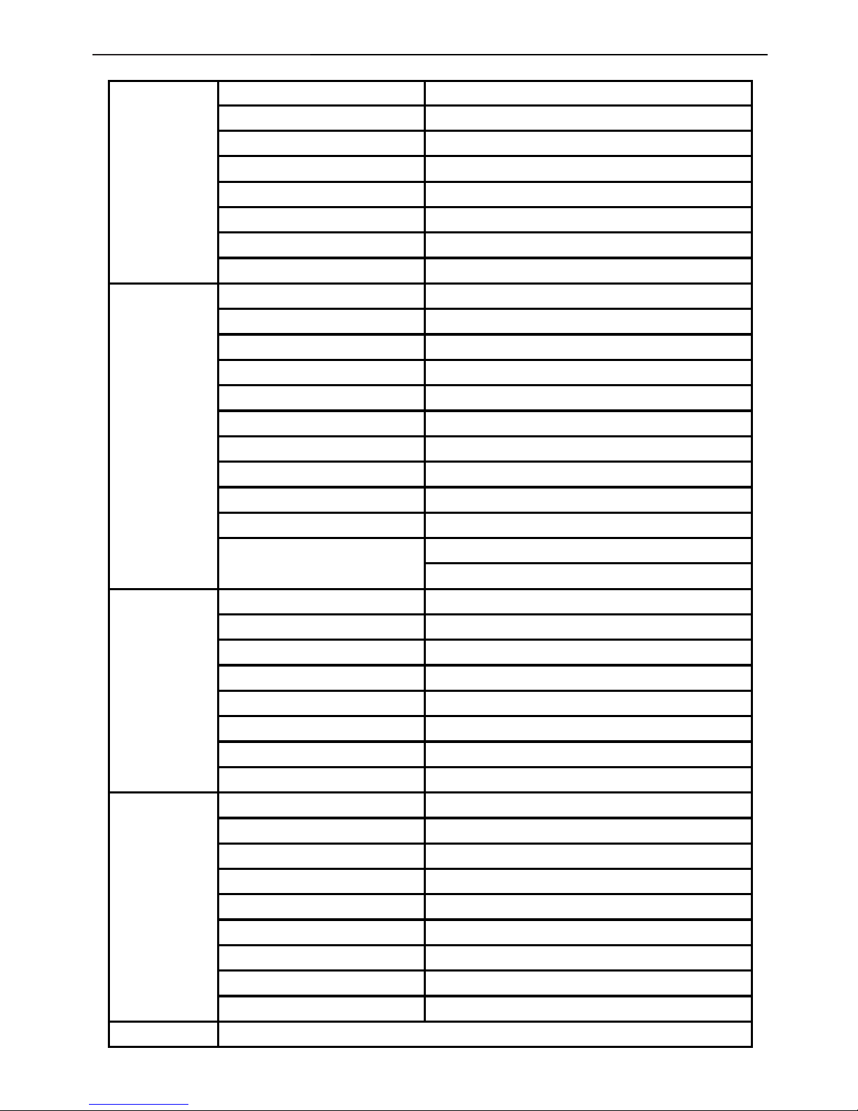
TABLE OF CONTENTS
Description Page Description Page
SAFETY NOTICE
ANY PERSON ATTEMPTING TO SERVICE THIS CHASSIS MUST FAMILIARIZE HIMSELF WITH THE CHASSIS
AND BE AWARE OF THE NECESSARY SAFETY PRECAUTIONS TO BE USED WHEN SERVICING
ELECTRONIC EQUIPMENT CONTAINING HIGH VOLTAGES.
Table Of Contents.......……..............................…........1
Revision List.…..................................................……......2
Important Safety Notice.……..............................……......3
1.Monitor Specification..................................………........4
2.LCD Monitor Description………….………………….......5
3.Operation Instruction…………….................……...........6
3.1.General Instructions...................................…...........6
3.2.Control Buttons…………….…..............……...............6
3.3.OSD Settings………….…...........................…............7
4.Input/Output Specification............……………...........9
4.1.Input Signal Connector............…………................9
4.2.Factory Preset Display Modes..........................9
4.3.Panel Specification.....………………..................10
5.Block Diagram…..…...................…………..................13
5.1.Software Flow Chart……………..…………....….......13
5.2.Electrical Block Diagram………….…………..….......15
6.Schematic……………......................................17
6.1 Main Board……..............................................17
6.2 Power Board…....……....................................21
7.PCB Layout..………….......................................23
7.1.Main Board………........................................23
7.2.Power Board....……....................................26
7.3. Audio Board………….....................................29
7.4 Key Board……………..................................29
8.Maintainability……….......................................30
8.1.Equipments and Tools Requirement...............30
8.2.Trouble Shooting…………..............................31
9.White-Balance, Luminance adjustment.............37
10.Monitor Exploded View………..…….…............39
11.BOM List…………………………………............41
12.Different Parts List………………………………53
CAUTION: USE A SEPARATE ISOLATION TRANSFOMER FOR THIS UNIT WHEN SERVICING

20" LCD Color Monitor Dixon N20W
2
Revision List
Version Release Date Revision History TPV Model Name
A00 Jun-12-2007 Initial release TA7CMADBW3DXAN
A01 Oct-12-2007 Second release TA7CMADBW3DXAG

20" LCD Color Monitor Dixon N20W
3
Important Safety Notice
Proper service and repair is important to the safe, reliable operation of all AOC Company Equipment. The service
procedures recommended by AOC and described in this service manual are effective methods of performing service
operations. Some of these service operations require the use of tools specially designed for the purpose. The special
tools should be used when and as recommended.
It is important to note that this manual contains various CAUTIONS and NOTICES which should be carefully read in
order to minimize the risk of personal injury to service personnel. The possibility exists that improper service
methods may damage the equipment. It is also important to understand that these CAUTIONS and NOTICES ARE
NOT EXHAUSTIVE. AOC could not possibly know, evaluate and advise the service trade of all conceivable ways in
which service might be done or of the possible hazardous consequences of each way. Consequently, AOC has not
undertaken any such broad evaluation. Accordingly, a servicer who uses a service procedure or tool which is not
recommended by AOC must first satisfy himself thoroughly that neither his safety nor the safe operation of the
equipment will be jeopardized by the service method selected.
Hereafter throughout this manual, AOC Company will be referred to as AOC.
WARNING
Use of substitute replacement parts, which do not have the same, specified safety characteristics may create shock,
fire, or other hazards.
Under no circumstances should the original design be modified or altered without written permission from AOC. AOC
assumes no liability, express or implied, arising out of any unauthorized modification of design.
Servicer assumes all liability.
FOR PRODUCTS CONTAINING LASER:
DANGER-Invisible laser radiation when open AVOID DIRECT EXPOSURE TO BEAM.
CAUTION-Use of controls or adjustments or performance of procedures other than those specified herein may result
in hazardous radiation exposure.
CAUTION -The use of optical instruments with this product will increase eye hazard.
TO ENSURE THE CONTINUED RELIABILITY OF THIS PRODUCT, USE ONLY ORIGINAL MANUFACTURER'S
REPLACEMENT PARTS, WHICH ARE LISTED WITH THEIR PART NUMBERS IN THE PARTS LIST SECTION OF
THIS SERVICE MANUAL.
Take care during handling the LCD module with backlight unit
-Must mount the module using mounting holes arranged in four corners.
-Do not press on the panel, edge of the frame strongly or electric shock as this will result in damage to the screen.
-Do not scratch or press on the panel with any sharp objects, such as pencil or pen as this may result in damage to
the panel.
-Protect the module from the ESD as it may damage the electronic circuit (C-MOS).
-Make certain that treatment person’s body is grounded through wristband.
-Do not leave the module in high temperature and in areas of high humidity for a long time.
-Avoid contact with water as it may a short circuit within the module.
-If the surface of panel becomes dirty, please wipe it off with a soft material. (Cleaning with a dirty or rough cloth may
damage the panel.)
20" LCD Color Monitor Dixon N20W
4
1. Monitor Specifications
LCD Panel
Model number N20W
Driving system TFT Color LCD
Size 510mm ( 20")
Pixel pitch 0.258mm(H) x 0.258mm(V)
Video R, G, B Analog lnterface
Separate Sync. H/V TTL
Display Color 16.7 million Colors
Dot Clock 146.25 MHz
Resolution
Horizontal scan range 31 kHz - 82 KHz
Horizontal scan Size(Maximum) 433.44 mm
Vertical scan range 56 Hz - 75 Hz
Vertical scan Size(Maximum) 270.9 mm
Optimal preset resolution 1680 x 1050 (60 Hz)
Highest preset resolution 1680 x 1050 (60 Hz)
Plug & Play VESA DDC2B / DDC-CI
Input Connector D-Sub 15pin
Input Video Signal Analog: 0.7Vp-p(standard), 75 OHM, Positive
Power Source 100~240VAC, 47~63Hz
Power Consumption
Active < 49W
Standby < 1W
Physical
Characteristics
Connector Type 15-pin Mini D-Sub
Signal Cable Type Detachable
Dimensions & Weight:
Height (with base)
398.5mm
Width
472.3mm
Depth
182 mm
Weight (monitor only)
4.4 kg
Weight (with packaging)
6.0 kg
Environmental
Temperature:
Operating 0° to 50°
Non-Operating -20°to 60°
Humidity:
Operating 10% to 85% (non-condensing)
Non-Operating 5% to 80% (non-condensing)
Altitude:
Operating 0~ 3000m (0~ 10000 ft )
Non-Operating 0~ 5000m (0~ 15000 ft )
Regulations
CE,TCO'03
20" LCD Color Monitor Dixon N20W
5
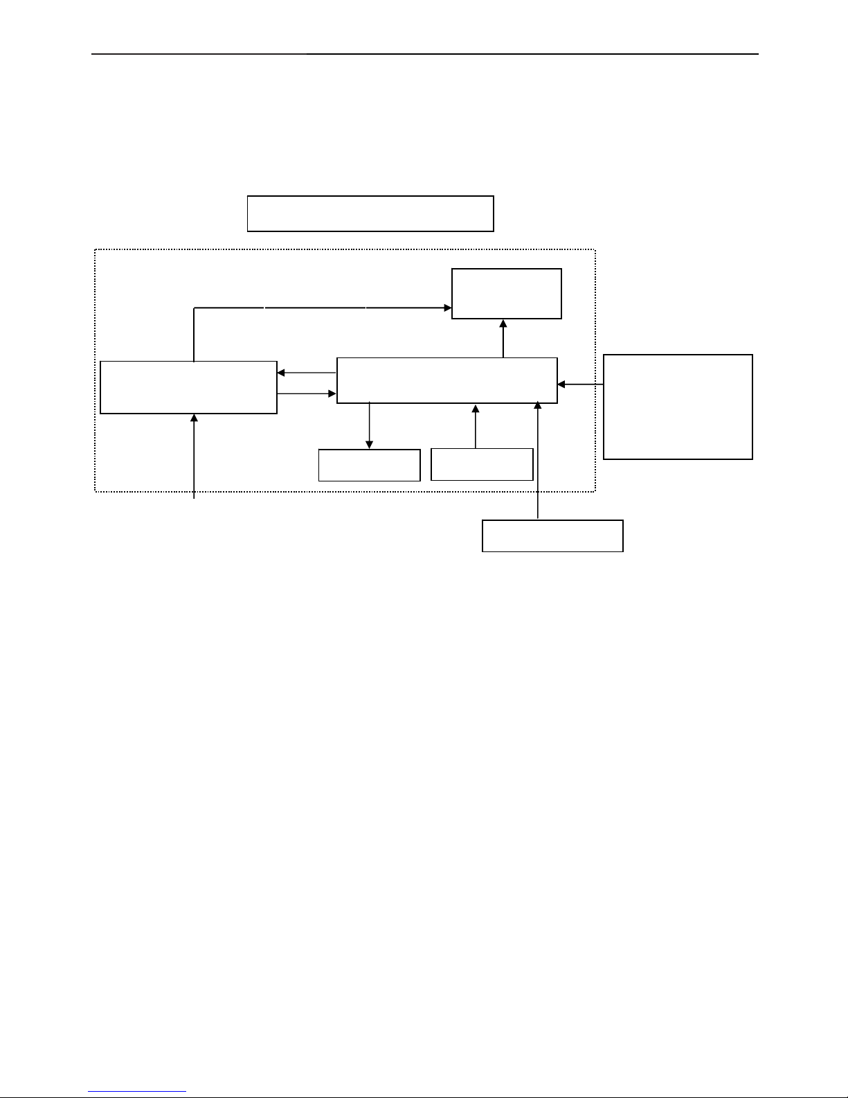
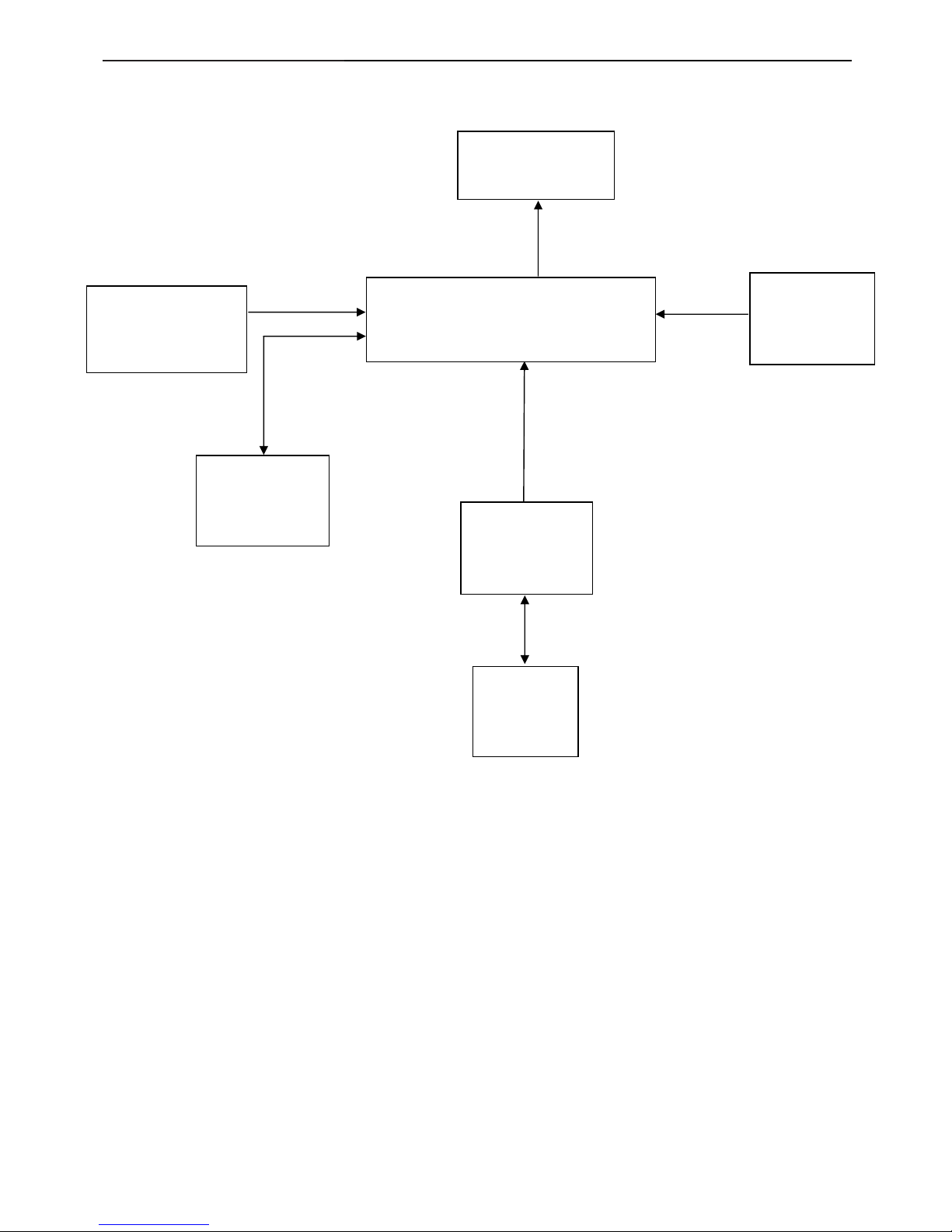
2. LCD Monitor Description
The LCD monitor will contain a main board, a power board, a key board and an audio board which house the flat
panel control logic, brightness control logic and DDC.
The power board will provide AC to DC Inverter voltage to drive the backlight of panel and the main board chips each
voltage.
AC-IN
100V-240V
Power board
(
Include: adapter, inverter)
Flat Panel and
CCFL backlight
Main Board
RS232 Connector
For white balance
adjustment in factory
mode
CCFL Drive.
Video signal, DDC
Monitor Block Diagram
Audio Board
HOST Computer
Key Board
20" LCD Color Monitor Dixon N20W
6
3. Operating Instructions
3.1 General Instructions
Press the power button to turn the monitor on or off. The other control knobs are located at front panel of the monitor.
By changing these settings, the picture can be adjusted to your personal preferences.
* The power cord should be connected.
* Press the power button to turn on the monitor. The power indicator will light up.
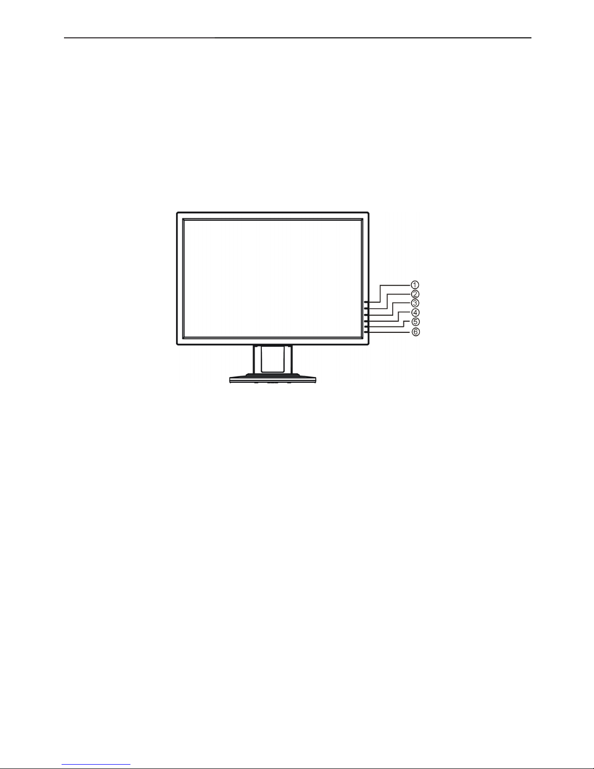
3.2 Control Buttons
1. Auto Config
2. Volume up / +
3. Volume down / -
4. Menu / Enter
5 .Power Indicator
6. Power Button

20" LCD Color Monitor Dixon N20W
7
3.3 OSD Settings
Main Menu
Item
Main Menu Icon
Sub Menu
Item
Sub Menu Icon Description
Luminance
Contrast
Contrast from Digital-register.
Brightness
Backlight Adjustment
Image Setup
Focus
Adjust Picture Phase to reduce
Horizontal-Line noise
Clock
Adjust picture Clock to reduce
Vertical-Line noise.
Image
Position
H. Position
Adjust the horizontal position of the
picture.
V. Position
Adjust the vertical position of the
picture.
Color Temp.
Warm N/A
Recall warm Color Temperature from
EEPROM.
Cool N/A
Recall cool Color Temperature from
EEPROM.
sRGB N/A
Recall sRGB Temperature from
EEPROM.
User / Red
Red Gain from Digital-register.
User /Green
Green Gain from Digital-register.
User / Blue
Blue Gain from Digital-register.
Auto Config
(Analog-Only
Model)
Yes N / A
Auto Adjust the H/V Position, Focus
and Clock of picture.
No N/A
Do not execute Auto Config, return to
main menu.

20" LCD Color Monitor Dixon N20W
8
OSD Setup
H. Position
Adjust the horizontal position of the
OSD.
V. Position
Adjust the vertical position of the
OSD.
OSD Timeout
Adjust the OSD timeout.
Language
Language N/A Select the language you like
Information
Information N/A
Show the resolution, H/V frequency
and input port of current input timing.
Reset
Yes N / A
Clear each old status of
Auto-configuration and set the color
temperature to Cool.
No N/A
Do not execute reset, return to main
menu.
Exit
N/A N/A Exit OSD
LED Indicators
Status LED Color
Full Power Mode Green
Active-off Mode Red

20" LCD Color Monitor Dixon N20W
9
4. Input/Output Specification
4.1 Input Signal Connector
Pin No. Description Pin No. Description
1. Video-Red 9. +5V
2. Video-Green 10. Detect Cable
3. Video-Blue 11. NC
4. NC 12. DDC-Serial Data
5. GND 13. H-Sync
6. GND-R 14. V-Sync
7. GND-G 15. DDC-Serial clock
8. GND-B
VGA connector layout
4.2 Factory Preset Display Modes
Stand Resolution
Horizontal
Frequency(KHz)
Vertical
Frequency(Hz)
Dos-mode 720 x 400 31.47 70.0
VGA 640 x 480 31.47 60.0
VGA 640 x 480 37.50 75.0
SVGA 800 x 600 37.879 60.0
SVGA 800 x 600 46.875 75.0
XGA 1024 x 768 48.363 60.0
XGA 1024 x 768 56.476 70.0
XGA 1024 x 768 60.02 75.0
XGA 1024 x 768 48.780 60.0
XGA 1024 x 768 60.241 75.0
SXGA 1280 x 1024 64.00 60.0
SXGA 1280 x 1024 80.00 75.0
WSXGA 1680 x 1050 65.29 60.0
20" LCD Color Monitor Dixon N20W
10
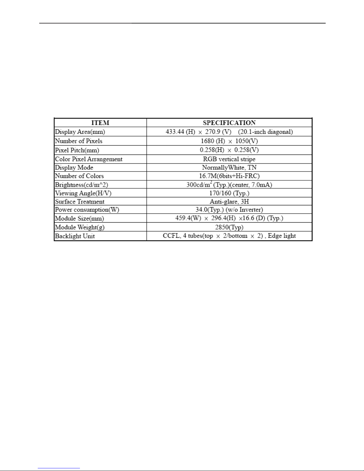
4.3 Panel Specification
4.3.1 General Description
CLAA201WA04 is 20.1” (51.11cm) color TFT-LCD (Thin Film Transistor Liquid Crystal Display) module composed of
LCD panel, LVDS driver ICs, control circuit and backlight(CCFL, 4 tubes). By applying 8 bit digital data
(6bits+Hi-FRC), 1680×1050, drived by 5 voltages,16.7M-color images are displayed on the 20.1” diagonal screen.
The module structure is fixed by iron frame, without the inverter for the backlight. Interface of data and control signals
is type.
4.3.2 Display Characteristics

20" LCD Color Monitor Dixon N20W
11
4.3.3 Optical Characteristics
Ta=25℃,VCC=5.0V
4.3.4 Electrical Characteristics
(1) TFT-LCD
Ta=25℃

20" LCD Color Monitor Dixon N20W
12
(2) Backlight

20" LCD Color Monitor Dixon N20W
13
5. Block Diagram
5.1 Software Flow Chat
1
2
N
Y
5
Y
N
10
Y
N
12
Y
N
7
Y
N
6
4
3
9
14
11
13
Y
N
15
Y
N
16
17
19
Y
N
18

20" LCD Color Monitor Dixon N20W
14
1) MCU initialize.
2) Is the EPROM blank?
3) Program the EPROM by default values.
4) Get the PWM value of brightness from EPROM.
5) Is the power key pressed?
6) Clear all global flags.
7) Are the AUTO and SELECT keys pressed?
8) Enter factory mode.
9) Save the power key status into EPROM.
Turn on the LED and set it to green color.
Scalar initializes.
10) In standby mode?
11) Update the lifetime of back light.
12) Check the analog port, are there any signals coming?
13) Does the scalar send out an interrupt request?
14) Wake up the scalar.
15) Are there any signals coming from analog port?
16) Display "No connection Check Signal Cable" message. And go into standby mode after the message
disappear.
17) Program the scalar to be able to show the coming mode.
18) Process the OSD display.
19) Read the keyboard. Is the power key pressed?
20" LCD Color Monitor Dixon N20W
15
5.2 Electrical Block Diagram
5.2.1 Main Board
EEPROM
M24C02
(U404)
EEPROM
24LC16B/SNG
(U403)
Panel Interface
(CN101)
SDA
SCL
Crystal
14.318MHZ
(X401)
Flash Memory
PM25LV010A-100
(U402)
Scalar TSUMU58WHJ-LF
(Include MCU, ADC, OSD)
(
U401
)
H sync
V sync
RGB
VGA_SDA,
VGA
_
SCL
D-Sub
Connector
(CN405)

20" LCD Color Monitor Dixon N20W
16
5.2.2 Inverter/Power Board
DIM
DIM
EMI filter
Start Circuit: R905
PWM
Control IC
Transformer
AC input
12V
ON/OFF
Control
PWM
Control IC
Feedback
Circui
t
Output
Circuit
Transformer
MOSFET
Over
Voltage
Lamp
ON/OFF
5V
Bridge
Rectifier
and Filter
Feedback
Circuit
Rectifier
diodes
 Loading...