

Page 1

HB Coupling Expander
Instructions
Vice or Bench Mounted
Hand Operated
Pull Through Type
Used to attach:
All 520-H Series Holedall Petroleum ttings ¾" - 2"
All 570-H & 580-H Series Holedall Petroleum ttings
Page 2

HB Coupling Expander Instructions
DESCRIPTION:
The HB Expander is a hand operated pull through type expander. It is used in a xed location
for small production runs or as a portable repair type expander.
The HB Expander will attach all sizes of Dixon Holedall Petroleum 570-H and 580-H series
(curb pump) couplings and sizes ¾" through 2" of 520-H series (fuel oil) couplings.
INSTALLATION:
The HB Expander is shipped assembled except for attaching the handles and threading the
drive screw through the drive screw nut. It can be held in a bench vice or secured to a bench.
Using either method, the expander should be positioned so that the handles overhang sufciently to give
freedom of movement when turning.
MAINTENANCE:
1. The Drive Screw No. 5 must be kept well lubricated with graphite grease.
2. Oil periodically where indicated on Body No. 1.
OPERATION:
To expand couplings sizes through 1":
1. Select the proper size reducer (if male coupling), reducer and close nipple (if female coupling).
Screw reducer onto Thrust Connector No. 3 by hand, then screw male coupling into reducer
by hand, or if a female coupling, screw onto close nipple until it stops on the washer seat.
2. Position Drive Screw No. 5 (use ½" wrench on ats to turn drive screw) so that the end with
the tapped hole is approximately ush with the front end (threaded end) of the coupling.
3. Select the proper size punch and screw it into Drive Screw No. 5 using a ½" wrench to tighten.
Hold Drive Screw No. 5 from turning and turn the handles clockwise until punch enters coupling
under slight pressure. (Lubricating punch is not necessary - Dixon Holedall Petroleum ttings
are pre-lubricated).
4. To assemble 520-H series (fuel oil):
Place proper size ferrule on the hose so that the end of the hose is ush with the turned
over portion of the ferrule (end of hose must be cut square). Keeping the ferrule stationary
to the hose, slide the assembly over the punch and onto the shank of the coupling until top
of ferrule is 1/8" from coupling face. Holding the hose in place, slide the ferrule ush against
the coupling face. This allows the turned over portion of the ferrule to be anchored properly
during the expansion process.
2
Dixon Valve & Coupling, Call 800.355.1991
HBEXP_web-411
Page 3

HB Coupling Expander Instructions
OPERATION (continued):
5. To assemble 570-H & 580-H series (curb pump):
Push hose over the punch and into the coupling until hose bottoms out. (The easiest way
to ensure proper insertion depth is to measure and mark the coupling shank depth on the
hose).
6. Turn handles clockwise until resistance to turning ceases - indicating expansion is complete.
7. After expansion has been completed, remove Thrust Connector No. 3 from expander.
Unscrew Thrust Connector and reducer as a unit from coupling. Replace Thrust Connector
in machine, then remove Punch. Machine is now ready for next expansion.
To expand couplings sizes 1¼" through 2":
1. Drive Screw No. 5 must be reversed. Remove Drive Screw from Nut No. 2, reverse Drive
Screw and reassemble with Nut No. 2.
2. Select proper size reducer or reducer nipple. Screw coupling onto reducer (or reducer nipple).
3. Advance Drive Screw No. 5 through coupling until keyed extension of Drive Screw projects
beyond coupling.
4. Slide expanding punch onto keyed extension of Drive Screw. Screw on Lock Nut No. 7.
Turn handles clockwise until punch enters coupling under slight pressure.
5. To assemble 520-H series (fuel oil):
a) Place proper size ferrule on the hose so that the end of the hose is ush with the turned
over portion of the ferrule (end of hose must be cut square). Keeping the ferrule stationary
to the hose, slide the assembly over the punch and onto the shank of the coupling until top
of ferrule is 1/8" from coupling face. Holding the hose in place, slide the ferrule ush against
the coupling face. This allows the turned over portion of the ferrule to be anchored properly
during the expansion process.
b) Turn handles clockwise until resistance to turning ceases - indicating expansion is complete.
6. After expansion has been completed, remove Thrust Connector from machine. Unscrew
Thrust Connector No. 3 and reducer as a unit from coupling. Replace Thrust Connector
in machine. Remove Punch, machine is now ready for next expansion.
CAUTION !!
After starting the expansion of a coupling, the handles must never be turned counter clockwise. The Thrust
Bearing is a single direction action and reverse operation of the machine will
damage the Drive Screw.
HBEXP_web-411
Dixon Valve & Coupling, Call 800.355.1991
3
Page 4
HB Coupling Expander Instructions
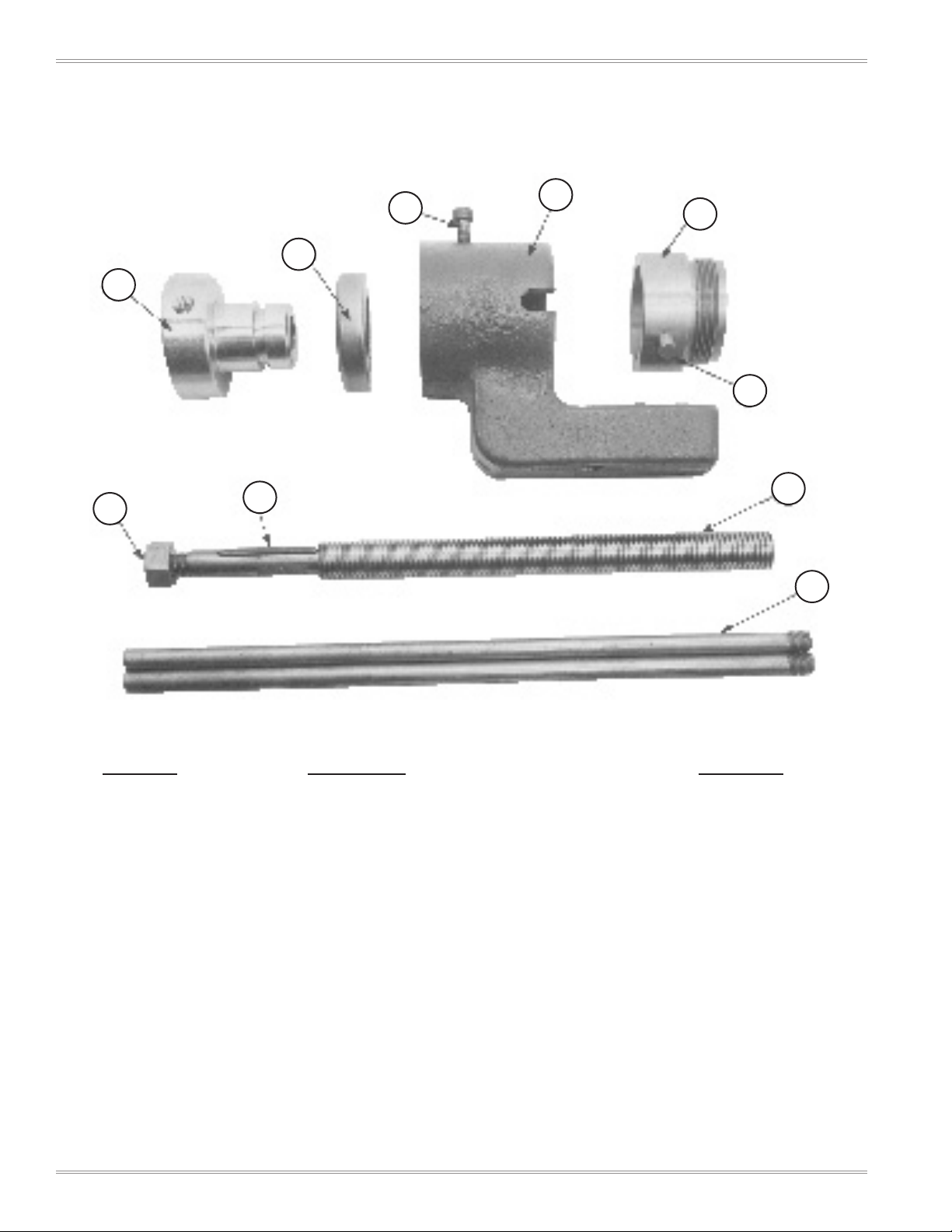
PARTS LIST FOR
HB EXPANDER
8
3
9
2
4
1
7
10
5
6
PHOTO # PART NAME PART #
1 Body 2500HB0001
2 Drive Screw Nut 2500HB0002
3 Thrust Connector 2500HB0003
4 Thrust Connector Pin (2 required) 2500HB0004
5 Drive Screw with Key 2500HB0005
6 Handle (2 required) 2500HB0006
7 Punch Retaining Nut 25000HSP11
8 Lock Screw 2500HB0007
9 Thrust Bearing 2500HB0008
10 Key 25000HSP15
4
Dixon Valve & Coupling, Call 800.355.1991
HBEXP_web-411
Page 5

HB Coupling Expander Instructions
TOOLING FOR
HB EXPANDER
11
23
18
12
24
19
13
25
14
20
26
15
21
16
22
3
17
PHOTO # PART NAME PART #
11 5/8" Expanding Punch 25000HTL01
12 3/4" Expanding Punch 25000HTL02
13 1" Expanding Punch 25000HTL03
14 1¼" Expanding Punch 25000HTL04
15 1-3/8" Expanding Punch 25000HTL05
16 1½" Expanding Punch 25000HTL06
17 2" Expanding Punch 25000HTL07
18 2" x 3/4" Standard Reducer 2500HBTL01 (BR2075)
19 2" x 1" Standard Reducer 2500HBTL02 (BR2010)
20 2" x 1¼" Standard Reducer 2500HBTL03 (BR2012)
21 2" x 1½" Standard Reducer 2500HBTL04 (BR2015)
22 2" Standard Coupling 2500HBTL05 (RHC200)
23 3/4" x 1-3/8" Close Nipple 2500HBTL06 (CN075)
24 1" x 1½" Close Nipple 2500HBTL07 (CN100)
25 1¼" x 1-5/8" Close Nipple 2500HBTL08 (CN125)
26 1½" x 2-3/4" Close Nipple 2500HBTL09 (CN150)
HBEXP_web-411
Dixon Valve & Coupling, Call 800.355.1991
5
Page 6

HB Coupling Expander Instructions
EFFECTIVE JANUARY 2009
HB Manual Coupling Expanding Machine
Coupling Types: 520-H, 570-H and 580-H
Coupling Sizes: 5/8" to 2"
Part Number Description
2500HB0000
HB Coupling Expanding Machine
HB expander includes the following replaceable parts
Part Number Description
2500HB0001
2500HB0002
2500HB0003
2500HB0004
2500HB0005
2500HB0006
2500HB0007
2500HB0008
25000HSP11
25000HSP15
HB-201 body
HB-202 drive screw nut
HB-204 thrust connector
HB-203 thrust connector pin (2 required)
HB-207 drive screw with key
HB-208 handle (2 required)
HB-209 lock screw
HB-101 thrust bearing
H-213 punch retaining nut
H-212 key
Tooling Needed for HB Expander
Punch, reducer and close nipple for each size.
2" requires punch and standard coupling ONLY.
For 1-3/8" fittings, reducers and nipples use 1½".
Part Number Description
25000HTL01
25000HTL02
25000HTL03
25000HTL04
25000HTL05
25000HTL06
25000HTL07
2500HBTL01
2500HBTL02
2500HBTL03
2500HBTL04
2500HBTL05
2500HBTL06
2500HBTL07
2500HBTL08
2500HBTL09
H-820 5/8" punch
H-607 3/4" punch
H-601 1" punch
H-608 1¼" punch
H-602 1-3/8" punch
H-603 1½" punch
H-604 2" punch
HB-106 2" x 3/4" standard reducer (BR2075)
HB-105 2" x 1" standard reducer (BR2010)
HB-104 2" x 1¼" standard reducer (BR2012)
HB-103 2" x 1½" standard reducer (BR2015)
HB-102 2" standard coupling (RHC200)
HB-110 3/4" x 1-3/8" close nipple (CN075)
HB-109 1" x 1½" close nipple (CN100)
HB-108 1¼" x 1-5/8" close nipple (CN125)
HB-107 1½" x 2-3/4" close nipple (CN150)
6
Dixon Valve & Coupling, Call 800.355.1991
HBEXP_web-411
 Loading...