

Page 1
Instruction & Operation Manual
Read and understand this manual prior to
installing, operating or servicing this equipment
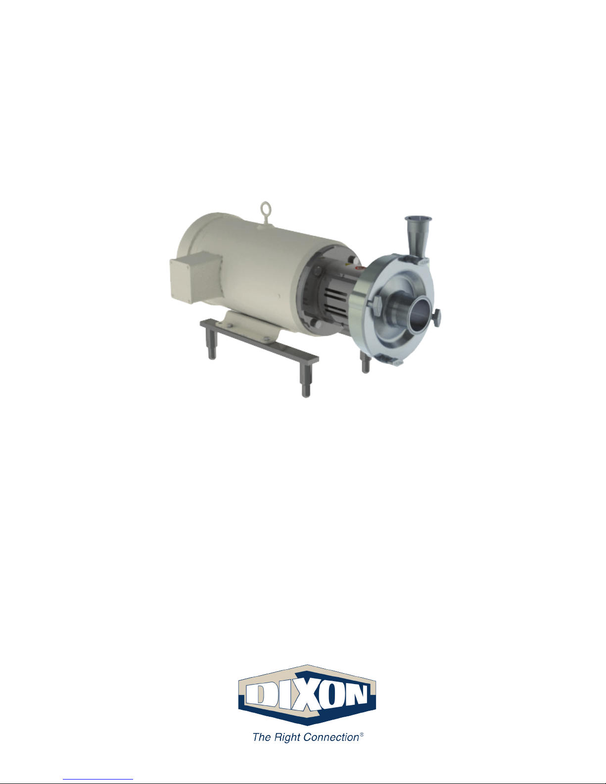
ExD Series Centrifugal Pump
July 2018
Page 2
2 Instruction & Operation Manual800.789.1718
Table of Contents
Use only replacement parts and devices recommended by the manufacturer to maintain the
integrity of the equipment. Make sure the parts are properly matched to the equipment series,
model, serial number and revision level of the equipment.
Safety labels are placed on every pump. Do not remove any labeling on any ExD Series pump.
Replace any label that is missing.
DO NOT modify any Dixon Sanitary product. Non-factory modications could create hazardous
conditions and voids all warranties. DO NOT attempt to use a Dixon Sanitary product in any
application that exceeds the product rating.
Safety Information
The following DANGER, WARNING and CAUTION signs are contained in this manual.
To avoid serious injury and/or possible damage to equipment, pay attention to these messages.
Hazards or unsafe practices which could result in severe personal injury or death.
The word DANGER is used in the most extreme cases.
Hazards or unsafe practices which could result in minor or moderate injury.
May also be used to alert against an unsafe operating or maintenance practice.
Indicates a potentially hazardous situation which, if not avoided, could result in
death or serious injury.
Safety ...........................................................2
Care of Stainless Steel .................................3
Introduction ...................................................4
Technical Information....................................5
Dimensions ............................................... 6-7
Installation ....................................................8
Unpacking .............................................8
Tools needed .........................................8
Assembly .................................................9-11
Installation ............................................ 12-15
Electrical .....................................................15
Pump Operation ................................... 16-18
Recommended Maintenance................ 18-20
Pump Casing and Impeller ..................18
Gaskets and O-rings ...........................18
Mechanical Seals ................................18
Motor Maintenance..............................19
Disassembly ........................................20
Casing Drain Options .................................21
Troubleshooting .................................... 22-23
Model and Part Numbers............................24
ExD 100 / 110 ......................................25
ExD 120 / 130......................................26
Casing Drain Options 100 Series ........26
ExD 200 / 210......................................27
ExD 220 / 230......................................28
Casing Drain Options 200 Series ........28
Repair Kits ..................................................29
Warranty .....................................................30
Page 3

PUMP
3Instruction & Operation Manual 800.789.1718
Care of Stainless Steel
The stainless steel components in Dixon Sanitary equipment are machined, welded and assembled by skilled craftsmen using
manufacturing methods that preserve the corrosion-resistant quality of the stainless steel.
Retention of corrosion-resistant qualities under processing conditions requires regular attention to the precautions listed below.
1. Regularly check all electrical devices connected to the equipment for stray currents caused by improper
grounding, damaged insulation or other defects. Corrosion: Pitting often occurs when stray currents
come in contact with moist stainless steel.
2. Never leave rubber mats, ttings, wrenches, etc. in contact with stainless steel. Corrosion: Pitting or galvanic action. Objects
retard complete drying, preventing air from reforming the protective oxide lm. Galvanic corrosion occurs when two dissimilar
metals touch when wet.
3. Immediately rinse equipment after use with warm water until the rinse water is clear. Clean the equipment (manual or CIP)
as soon as possible after rinsing. Corrosion: discoloration, deposits, pitting. Product deposits often cause pitting beneath the
particles.
4. Use only recommended cleaning compounds. Purchase chemicals from reputable and responsible chemical manufacturers
familiar with stainless steel processing equipment, they continuously check the effects of their products on stainless steel.
5. Use cleaning chemicals exactly as specied by the manufacturer. Do not use excessive concentrations, temperatures or
exposure times. Corrosion: Pitting, discoloration, stress cracks. Permanent damage often occurs from excessive chemical
concentrations, temperatures or exposure times.
6. For manual cleaning, use only soft non-metallic brushes, sponges or pads. Brush with the grain on polished surfaces, avoid
scratching the surface. Corrosion: Pitting, scratches. Metal brushes or sponges will scratch the surface and promote corrosion
over a period of time. Metal particles allowed to remain on a stainless steel surface will cause pitting.
7. Use chemical bactericides exactly as prescribed by the chemical manufacturer in concurrence with local health authority. Use
the lowest permissible concentration, temperature and exposure time possible. Flush immediately after bacterial treatment.
In no case should the solution be in contact with stainless steel more then 20 minutes. Corrosion: Protective lm destroyed.
Chlorine and other halogen bactericides can destroy the protective lm. A few degrees increase in temperature greatly
increases chemical activity and accelerates corrosion.
8. Regularly inspect the joints in pipelines. Be sure all connections are tight tting without binding. Corrosion: Crevice corrosion.
Small crevices caused by improperly seated gaskets will promote crevice corrosion. Stainless steel under stress will develop
stress cracking especially in the presence of bactericides containing chlorine.
9. Regularly inspect equipment for surface corrosion (i.e. pitting deposits, stress cracks, etc.). If deposit or color corrosion is
detected, remove it immediately using mild scouring powder and detergents. Rinse thoroughly and allow to air dry. Review
production and cleaning procedures to determine the cause. Note: If corrosion is not removed, the protective lm cannot be
restored and corrosion will continue at an accelerated rate.
Page 4
4 Instruction & Operation Manual800.789.1718
Introduction
This manual contains installation, operation, cleaning, repair instructions, model numbering structure and parts list for the Dixon ExD
Series centrifugal pump.
The Dixon ExD Series centrifugal pump is made up of two sections: the pump components (wet end) and the motor. The pump is
mounted to the motor with a stainless steel adapter and is coupled to the motor shaft with a stainless steel shaft sleeve and stub
shaft. The pump impeller on the ExD series centrifugal pump is threaded directly on to the pump stub shaft.
The casing of the ExD series centrifugal pump is a non-volute style casing that connects directly to the adapter. The design of the
casing and adapter features unique characteristics that allow the pump casing discharge outlet to be rotated to various positions
without disassembling the pump.
The motors used on the ExD series centrifugal pump are standard NEMA C-Face motors available as total enclosed fan cooled
(TEFC) or totally enclosed not ventilated (TENV) depending on the motor size. Other special motor options are available upon
request.
An adjustable leg kit is an option for mounting to the motor and is designed to meet sanitary requirements. This conguration
simplies the installation and ease of leveling.
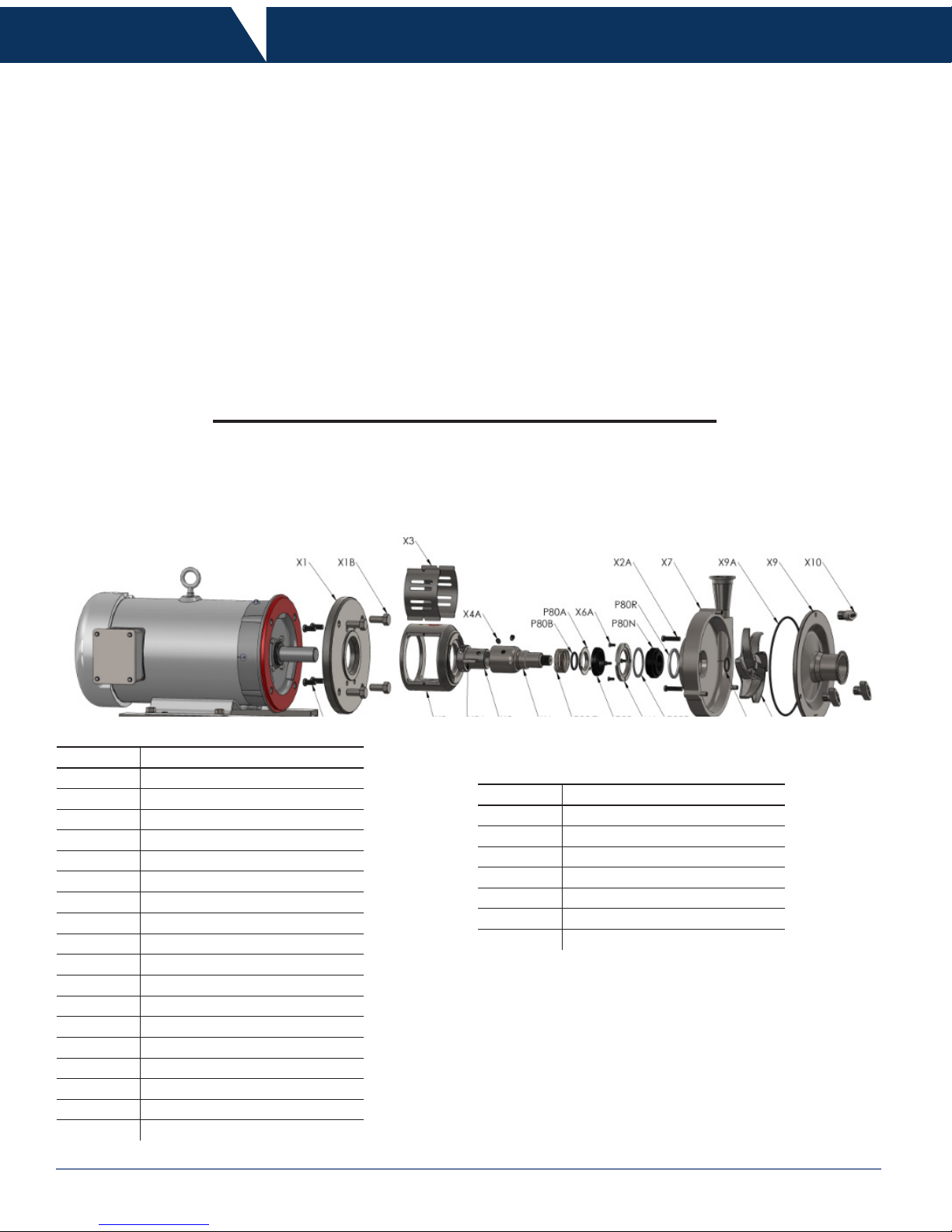
Key No. Description
X1 adapter to motor ange
X1A adapter bolts
X1B motor bolts and lock washers
X2 adapter
X2A adapter casing bolts
X3 guard with bolts
X4 stub shaft
X4A stub shaft set screws
X5 shaft sleeve with bolts
X5A shaft sleeve key
X6 seal gland
X6A seal gland bolts
X7 pump casing
X8 impeller
X8A impeller O-ring
X9 pump cover
X9A cover/casing O-ring
X10 cover wing nuts
Key No. Description
P80 rotary seal
P80A seal cup
P80B seal O-ring
P80C seal spring
P80P outboard gasket
P80N seal seat
P80R inboard gasket
DG Seal
BIll of Materials
Page 5

PUMP
5Instruction & Operation Manual 800.789.1718
Technical Information
• pump casing: 316L stainless steel
• impeller: CF3M (316L) stainless steel
• pump cover: 316L stainless steel
• stub shaft: 316L stainless steel
• rotary seal: silicon carbide, tungsten carbide, or carbon
• stationary seal: silicon carbide, ceramic, or tungsten carbide
• elastomers: FKM (standard), Buna, EPDM (other options
available, contact Dixon Sanitary)
• non-product contact components: 304 stainless steel
• nish: 32R
a
sanitary nish (other nishes available, contact
Dixon Sanitary)
• connections: clamp (other connections available, contact
Dixon Sanitary)
Materials of Construction
• nominal capacity: 500 GPM
• maximum head: 225 Feet
• temperature range: 32°F to 212°F (0°C to 100°C) (consult
Dixon Sanitary for higher temperatures)
• viscosity range: 0-500cP (consult Dixon Sanitary for higher
viscosities)
• nominal speed: up to 3500 RPM – 60 Hz
Performance Characteristics
• Dixon ExD Series centrifugal pumps use standard NEMA
TENV/TEFC C-face electric motors
• motors are available in a variety of different options including
washdown, explosion proof, premium efciency, general
purpose and severe duty
• voltage & frequency options:
• 1 Phase, 60Hz, 115/230VAC (1750 RPM & 3500 RPM)
• 3 Phase, 60Hz, 208-230/460 VAC (1750 RPM &
3500 RPM)
• 3 Phase, 60Hz, 575 VAC (1750 RPM & 3500 RPM)
• 3 Phase, 50Hz, 208-220/380 VAC (1450 RPM &
2900 RPM)
• Motor performance curves available upon request.
Motor Information
1750 RPM
3500 RPM
Page 6
6 Instruction & Operation Manual800.789.1718
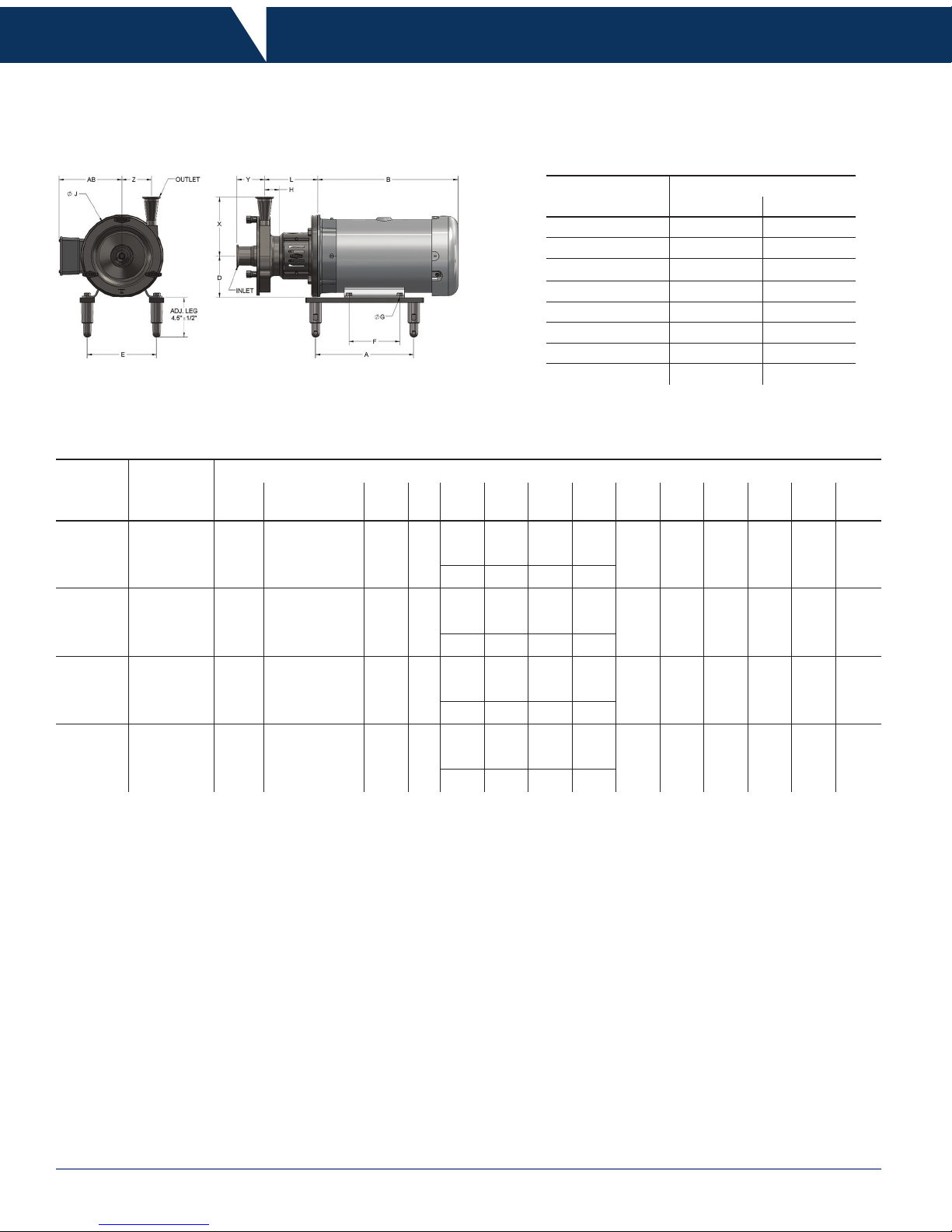
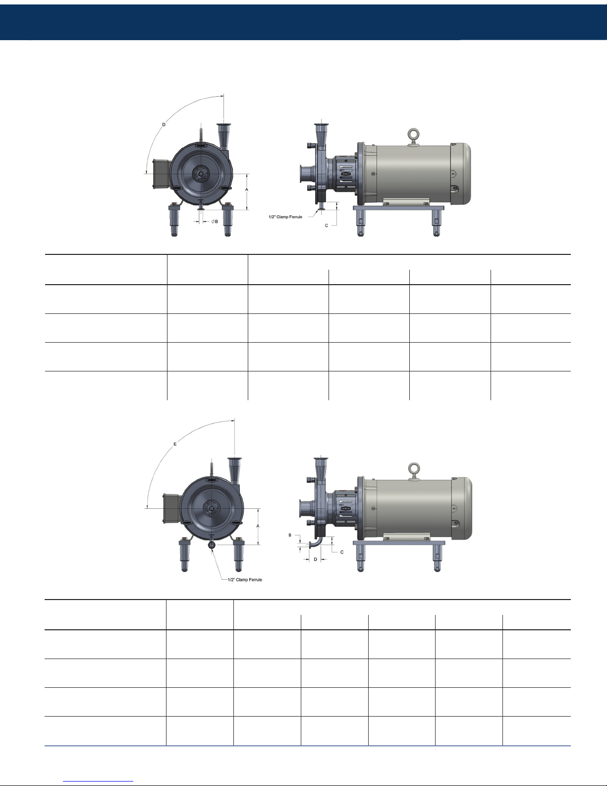
Dimensions
All dimensions are given in inches
• all dimensions are given in inches
• all dimensions given are for guidance only
Pump
Model
Connection Sizes
Inlet Outlet
EXD 100 1.00 1.00
EXD 110 1.50 1.00
EXD 120 2.00 1.50
EXD 130 2.50 1.50
EXD 200 2.50 2.00
EXD 210 3.00 2.00
EXD 220 3.00 2.50
EXD 230 4.00 2.50
Pump
Model
Motor
Frame
Size
Dimensions In Inches
A
AA
(Conduit Size)
AB B D E F
Ø
G H
Ø
J L X Y Z
ExD 100
ExD 110
56C 8.50 0.50 5.00
**
3.50
4.88 3.00
0.34
1.51 5.95 5.44 4.20 2.16 2.00143/145TC 9.50 0.75 5.25 5.50 4.00
182/184TC 10.63 0.75 5.88 4.50 7.50 4.50 0.41
ExD 120
ExD 130
56C 8.50 0.50 5.00
**
3.50
4.88 3.00
0.34
1.60 8.50 5.75 6.38 3.00 3.20143/145TC 9.50 0.75 5.25 5.50 4.00
182/184TC 10.63 0.75 5.88 4.50 7.50 4.50 0.41
ExD 200
ExD 210
182/184TC 10.63 0.75 5.88
**
4.50 7.50 4.50
0.41
1.84 9.94 7.63 7.62 3.34 3.50213/215TC 13.88 1.00 7.38 5.25 8.50 5.50
254/256TC 18.00 1.00 9.63 6.25 10.00 8.25 0.53
ExD 220
ExD 230
182/184TC 10.63 0.75 5.88
**
4.50 7.50 4.50
0.41
1.96 10.51 7.75 8.25 3.13 3.63213/215TC 13.88 1.00 7.38 5.25 8.50 5.50
254/256TC 18.00 1.00 9.63 6.25 10.00 8.25 0.53
** Contact Dixon Sanitary for detailed drawing.
Page 7
PUMP
7Instruction & Operation Manual 800.789.1718
Dimensions
All dimensions are given in inches
Pump Model
Casing Drain
Option
Dimensions In Inches
A
Ø
B C D
ExD 100/110
Option A
3.71 0.50 1.13
45°
Option J 90°
ExD 120/130
Option A
5.06 0.50 1.13
45°
Option J 90°
ExD 200/210
Option A
5.70 0.50 1.13
45°
Option J 90°
ExD 220/230
Option A
5.98 0.50 1.13
45°
Option J 90°
Pump Model
Casing Drain
Option
Dimensions In Inches
A B C D E
ExD 100/110
Option D
3.71 0.50 1.13 1.63
90°
Option K 45°
ExD 120/130
Option D
5.06 0.50 1.13 1.63
90°
Option K 45°
ExD 200/210
Option D
5.70 0.50 1.13 1.63
90°
Option K 45°
ExD 220/230
Option D
5.98 0.50 1.13 1.63
90°
Option K 45°
Page 8
8 Instruction & Operation Manual800.789.1718
Installation
Unpacking
• Carefully unpack all parts of the pump and inspect for damages that may have occurred during shipment. Report any damages to
the carrier immediately.
• The ports on the pump are protected with a plastic cover. If any covers are missing or damaged, inspect the ports on the pump
thoroughly for any damage.
Tools Needed
Key No. Part Number Description Pump Models Tools
X1A X1A-100-FAB 100 series ange to adapter bolts
ExD 100 - 110
3/16" allen
or hex
ExD 120 - 130
ExD 200 - 210
ExD 220 - 230
X1B
X1B-100-FMB56
100 series ange to motor bolts and lock washers 56C to
140TC frame
ExD 100 - 110
9/16" wrench
ExD 120 - 130
X1B-100-FMB18
100 series ange to motor bolts and lock washers 180TC to
250TC frame
ExD 200 - 210
3/4" wrench
ExD 220 - 230
X2A
X2A-100-ACB 100 series adapter to casing bolts
ExD 100 - 110
5/32" allen
or hex
ExD 120 - 130
X2A-200-ACB 200 series adapter to casing bolts
ExD 200 - 210
3/16" allen
or hex
ExD 220 - 230
X4A
X4A-100-DPSS 100 series shaft dog point set screw
ExD 100 - 110
5/32" allen
or hex
ExD 120 - 130
X4-200-DPSS 200 series shaft dog point set screw
ExD 200 - 210
3/16" allen
or hex
ExD 220 - 230
X5
X5-100-SL56 to
X5-100-SL18
100 series shaft sleeve w/bolts for 56C to 180TC frame
ExD 100 - 110
TP45 torx
plus driver
ExD 120 - 130
X5-200-SL18 to
X5-200-SL25
200 series shaft sleeve w/bolts for 180TC to 250TC frame
ExD 200 - 210
TP50 torx
plus driver
ExD 220 - 230
X6A
X6A-100-SGB 100 series seal gland bolt
ExD 100 - 110
3/32" allen
or hex
ExD 120 - 130
X6A-200-SGB 200 series seal gland bolt
ExD 200 - 210
1/8" allen or
hex
ExD 220 - 230
X7
X7-100-CASE-C to
X7-120-CASE-C
100-120 series pump casing with clamp outlet (cover studs)
ExD 100 - 110
5/32" allen
or hex
ExD 120 - 130
X7-200-CASE-C to
X7-220-CASE-C
200-220 series pump casing with clamp outlet (cover studs)
ExD 200 - 210
3/16" allen
or hex
ExD 220 - 230
X10
X10-100-WN 100 series cover wing nuts
ExD 100 - 110
adjustable
wrench
ExD 120 - 130
X10-200-WN 200 series cover wing nuts
ExD 200 - 210
ExD 220 - 230
N/A N/A general hand tools
ExD 100 - 230 soft mallet
phillips driver
O-ring pick
liquid thread
locker
Vernier
caliper
Page 9
PUMP
9Instruction & Operation Manual 800.789.1718
Assembly
1. Attach item (X1) motor ange to item (X2) adapter using the (4) socket head cap screws item (X1A). Ensure that the drain hole
in the bottom of the adapter (X2) and the drain slot in the back of the motor ange (X1) are facing the same direction.
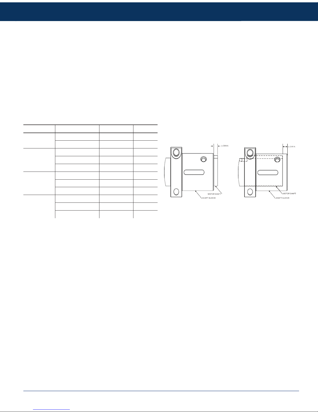
2. Setting the shaft sleeve:
a. Make sure that the motor shaft key (X5A) is removed from the motor prior to installing the shaft sleeve item (X5).
b. Slide the shaft sleeve (X5) on to the motor shaft with the shaft sleeve oriented such that the shaft sleeve bolts are closest to
the motor.
c. Tighten the shaft sleeve bolts until there is a slight resistance to movement between the shaft sleeve (X5) and the motor
shaft. The shaft sleeve (X5) should be able to be moved by hand, but still hold its position if your hand is removed.
d. Using a Vernier caliper set the shaft sleeve (X5) in place on the motor shaft using the table listed below.
e. Once the shaft sleeve (X5) is set at the proper dimension, tighten the shaft sleeve bolts according to the torque value listed in
the recommended torque value chart listed in this manual (Page 11). Recheck the position of the shaft sleeve to ensure that it
did not move while tightening the shaft sleeve bolts.
3. Install the stub shaft:
a. Install the stub shaft (X4) on the shaft sleeve (X5) making sure the keyways of the stub shaft engage properly with the keys
on the shaft sleeve.
b. Ensure that the set screws on the stub shaft are properly aligned with the two counter bores on the stub shaft sleeve.
c. Tighten stub shaft socket head set screws.
4. Install the adapter assembly (X1 & X2) from step 1 to the motor using the (4) adapter bolts. Apply liquid thread locker to the (4)
adapter bolts. Ensure that the adapter drain hole is facing down toward the ground.
5. Install the rotating seal/spring/cup assembly:
a. Place the seal spring (P80C) over the stub shaft (X4) and ensure that the seal spring is sitting completely at on the bottom
face of the stub shaft.
b. Place the seal O-ring (P80B) into the back of the rotating seal (P80).
c. Place the rotating seal (P80) and seal O-ring (P80B) assembly securely onto the seal cup (P80A) making sure to line up the
notches in the rotating seal with protruding tabs of the seal cup.
d. Slide the rotating seal (P80)/seal O-ring (P80B)/seal cup (P80A) assembly onto the stub shaft (X4) just until the bottom face
of the seal cup touches the seal spring (P80C).
e. Rotate the seal assembly while keeping the stub shaft (X4) stationary until the slot in the bottom of the seal cup (P80A) is
aligned with the stub shaft seal pin that extrudes from the stub shaft.
Pump Model Motor Frame Size DIM A (+/-)
ExD 100
ExD 110
56C 0.385 +
143TC to 145TC 0.243 +
ExD 120
ExD 130
56C 0.355 +
143TC to 145TC 0.209 +
182TC to 184TC 0.264 -
ExD 200
ExD 210
182TC to 184TC 0.506 +
213TC to 215TC 0.000
254TC to 256TC 0.627 -
ExD 220
ExD 230
182TC to 184TC 0.479 +
213TC to 215TC 0.024 -
254TC to 256TC 0.654 -
continued on next page ...
See page 4 for exploded view.
Page 10

10 Instruction & Operation Manual800.789.1718
Assembly
6. Install the stationary seal assembly:
a. Install the stationary inboard gasket (P80R) into the bottom of the pump casing (X7) stationary seal cavity. Ensure that the
gasket is sitting at and it centered properly by the slight counter bore in the bottom of the seal cavity.
b. Place the stationary seal (P80N) on top of the inboard stationary gasket (P80R).
c. Place the stationary outboard gasket (P80P) on top of the stationary seal.
d. Place the seal ring gland (X6) on top of the stationary outboard gasket (P80P) so that the part number on the seal ring gland
is facing up.
e. Apply liquid thread locker to the seal ring gland bolts (X6A) and thread the bolts through the seal ring gland and into the pump
casing (X7).
f. Tighten the seal ring gland bolts (X6A) in a star pattern according to the recommended torque value chart given in this
manual.
7. Attach the pump casing to the adapter:
a. Lower the pump casing (X7) onto the pump adapter (X2) compressing the rotating seal assembly as you lower the casing.
b. Press down on the casing (X7) making sure that casing is sitting rmly against the adapter (X2).
c. Thread the adapter-casing bolts (X2A) through the adapter slots and into the threaded holes on the back of the pump casing
(X7). Note: apply liquid thread locker to the bolts.
d. Thread the adapter-casing bolts (X2A) in until nger tight. Adjust the position of the casing by rotating until the desired
position is reached.
e. Tighten the adapter casing-bolts (X2A) evenly and torque to the value given in the recommended torque value chart given in
this manual.
8. Attach the impeller to the stub shaft:
a. Apply food grade lubricant to the impeller O-ring (X8A) and place the O-ring in the O-ring groove of the stub shaft (X4).
b. Thread the impeller (X8) onto the pump stub shaft (X4). Tighten the impeller until you feel it bottom out against the stub shaft
(X4). Note: place an Allen wrench in the leak detection hole on the base of the stub shaft (X4) to lock against the adapter (X2)
while tightening the impeller.
9. Install the front cover onto the casing:
a. Apply food grade lubricant to the front cover O-ring (X9A) and place the O-ring into the O-ring groove of the front cover (X9).
b. Place the front cover (X9) onto the pump casing (X7).
c. Install the front cover wing nuts (X10) onto the threaded casing studs. If the stud is damaged in any way, it can be replaced
with a standard cup point set screw (5/16-18 x 1¼ for all 100 series models and ⅜-16 x 1¼ for all 200 series models).
d. Tighten the front cover wing nuts (X10) evenly using a wrench on the ats of the wing nuts.
e. Rotate the pump stub shaft (X4) to ensure that you do not hear any metal to metal contact of the impeller with the front cover.
If there is contact, disassemble and recheck the setting of the stub shaft sleeve (X5).
10. Install the adapter guards:
a. Using the provided guard bolts, attached the two safety guards (X3) to the adapter (X2) and tighten securely.
... continued from previous page
Page 11

PUMP
11Instruction & Operation Manual 800.789.1718
Assembly
Key No. Part Number Description Pump Models Torque Value
X1A X1A-100-FAB 100 series ange to adapter bolts
ExD 100 - 110
20 ft.-lbs. 28 N-m
ExD 120 - 130
ExD 200 - 210
ExD 220 - 230
X1B
X1B-100-FMB56
100 series ange to motor bolts and
lock washers 56C to 140TC frame
ExD 100 - 110
20 ft.-lbs. 28 N-m
ExD 120 - 130
X1B-100-FMB18
100 series ange to motor bolts and
lock washers 180TC to 250TC frame
ExD 200 - 210
50 ft.-lbs. 68 N-m
ExD 220 - 230
X2A
X2A-100-ACB 100 series adapter to casing bolts
ExD 100 - 110
12 ft.-lbs. 17 N-m
ExD 120 - 130
X2A-200-ACB 200 series adapter to casing bolts
ExD 200 - 210
20 ft.-lbs. 28 N-m
ExD 220 - 230
X4A
X4A-100-DPSS 100 series shaft dog point set screw
ExD 100 - 110
11 ft.-lbs. 15 N-m
ExD 120 - 130
X4-200-DPSS 200 series shaft dog point set screw
ExD 200 - 210
20 ft.-lbs. 28 N-m
ExD 220 - 230
X5
X5-100-SL56 to
X5-100-SL18
100 series shaft sleeve with bolts for
56C to 180TC frame
ExD 100 - 110
24 ft.-lbs. 33 N-m
ExD 120 - 130
X5-200-SL18 to
X5-200-SL25
200 series shaft sleeve with bolts for
180TC to 250TC frame
ExD 200 - 210
45 ft.-lbs 61 N-m
ExD 220 - 230
X6A
X6A-100-SGB 100 series seal gland bolt
ExD 100 - 110
3 ft.-lbs 4 N-m
ExD 120 - 130
X6A-200-SGB 200 series seal gland bolt
ExD 200 - 210
6 ft.-lbs. 8 N-m
ExD 220 - 230
Recommended Torque Values
Page 12

12 Instruction & Operation Manual800.789.1718
• Pump will perform at its best when located as close as possible to the liquid supply.
• Supply piping should be short and straight to ensure the pump has an adequate supply of liquid to it at all times.
• The pump should be located in an area where it is easy to inspect and do preventative maintenance or repair.
Location
The pump can be easily leveled by installing the optional leg kit. Using an adjustable wrench, t the wrench to the wrench at
shown in the diagram below. When viewed from the top, turn
the wrench in a counter-clockwise direction to lower the leg, or clockwise direction to raise the leg.
Optional Leg Kit Installation and Leveling
Installation
Page 13

PUMP
13Instruction & Operation Manual 800.789.1718
Installation
Piping: General Guidelines
Improper piping can lead to a number of
problems with pump performance which
could lead to increased maintenance costs.
• Ensure piping is independently supported at both the suction
and discharge ports of the pump. (see the diagram at right)
• Piping must be properly aligned to prevent any strain on
pump casing.
• Try to have as few bends as possible in all piping.
PROXIMITY
TO
VOLUTE
TUBING
HANGER
TUBING
HANGER
Piping: Suction Guidelines
• Make sure line sizes used are equal to or larger than suction side (supply side) port connections on the pump.
• Suction side needs to be as short and straight as possible. Any restrictions will affect the NPSHa. Adequate NPSHa must be
ensured.
• Maintain a straight length of pipe at a minimum of 8 x diameters long at the pump inlet. (see the diagram below)
DIAMETER
MINIMUM LENGTH = 8 x DIAMETER
continued on next page ...
Page 14

14 Instruction & Operation Manual800.789.1718
Installation
• To prevent air leaks, ensure all joints in suction line are well
sealed.
• Use an eccentric reducer with straight side up to prevent air
pockets from forming which will result in a decrease in pump
efciency. (see the diagram at left)
• To prevent a high point in the suction line resulting in an air
pocket being formed affecting proper pump performance,
horizontal suction pipes must have a gradual rise to the
pump.
Piping: Suction Guidelines
... continued from previous page
ECCENTRIC
REDUCER
CONCENTRIC
REDUCER
Piping: Discharge Guidelines
• Discharge side should be short and direct. Use a minimal
number of restrictions. (see the diagram to the right)
• Vertical or top horizontal pump discharge position is
preferred. (see the diagram at the left)
• While increasing the discharge side line size is
recommended, please note:
> Using too large of a line size may lead to motor overload
and cavitation.
> Using a smaller than recommend line size will increase
the pump head but lower the ow.
• Types of reducers to use:
> If vertical discharge – concentric
> If horizontal discharge – eccentric with straight side down
DIAMETER
MINIMUM LENGTH
= 10 x DIAMETER
BETWEEN
0° & 90°
Page 15

PUMP
15Instruction & Operation Manual 800.789.1718
Installation
• An isolation valve should be installed at both the suction and
discharge sides of the pump. This will allow you to remove
the pump for preventative maintenance or repair without the
need to drain your system.
(see the diagram to the right)
• If pump is not in a ooded suction condition, install either a
foot valve or system check valve to ensure pump casing is
ooded for priming.
• In order to provide pump ow rate control, a control valve
should be installed in the discharge piping to prevent motor
overload.
Piping: Valve Location
MINIMUM LENGTH
= 10 X DIAMETER
DIAMETER
CHECK
VALVE
CONTROL
VALV E
MINIMUM LENGTH = 8 X DIAMETER
DIAMETER
ISOLATION
VALVE
PSI
All power must be off and locked out during the installation process.
Only registered electricians should do the electrical installation.
Electrical
• Follow motor manufacturer’s installation procedures.
• Verify motor nameplate data is compatible with existing
electrical supply.
• Verify pump rotation. An arrow sticker is supplied with every
pump to show correct pump rotation. If the arrow stickers are
missing, contact Dixon Sanitary for a replacement.
• Correct rotation is counter clockwise when facing pump inlet
connection.
Page 16

16 Instruction & Operation Manual800.789.1718
Operation
Priming the Pump
SUPPLY SOURCE
ABOVE PUMP LEVEL
CHECK
VALVE
CONTROL
VALV E
ISOLATION
VALVE
To avoid damage to the pump, the pump casing must be ooded with liquid BEFORE starting the pump.
Fluid supply above the pump:
1. Open supply line isolation valve.
2. Vent any entrapped air by opening the discharge valve.
3. After casing is ooded, start pump.
If the uid supply is below the pump see page 17.
Note: This is not a self priming pump. Other means must be installed to prime the pump.
Page 17

PUMP
17Instruction & Operation Manual 800.789.1718
Operation
Priming the Pump
CHECK
VALVE
CONTROL
VALV E
ISOLATION
VALVE
FOOT
VALV E
EXTERNAL PRIMING
SUPPLY LINE
Fluid supply below the pump:
1. Close discharge valve and open air vents.
2. Open valve in external priming supply line. Close once liquid
ows from vent valves.
3. Close vent valves.
4. Turn off priming supply line.
5. Start pump.
If the uid supply is above the pump see page 16.
Note: It is recommended to use a foot/check valve system to keep the pump primed. Otherwise the pump must be primed before
each operation.
Page 18

18 Instruction & Operation Manual800.789.1718
Operation
Starting the Pump
1. Ensure pump suction is ooded using either method as explained in the previous priming section.
2. Check for any closed valves or obstructions in the suction and discharge lines.
3. Start the motor.
4. Verify liquid is owing and there is no piping connection or mechanical seal leaks.
5. Adjust throttling valve on discharge line to desired ow.
Stopping the Pump
1. Shut off power to motor.
2. Suction and discharge valves are to be shut off.
3. Be advised the pump does not act as a shut off valve. The liquid will ow freely though the pump.
Recommended Maintenance
Preventative maintenance will increase the life of your pump. Documentation of any maintenance will help to diagnose potential
problems and help in determining solutions.
Pump Casing and Impeller
1. Inspect the pump casing and impeller for any signs of possible wear.
2. Replace any stainless components if they show any sign of damage.
3. Inspect the pump casing and impeller frequently if in a severe duty application.
See troubleshooting guide on pages 22-23, for possible solutions.
Gaskets and O-rings
All gaskets and O-rings should be inspected when the pump is undergoing routine maintenance. If the pump is in a severe duty
application, the soft good components (gaskets and O-rings) should be inspected more frequently. Any soft good component that
shows signs of degradation e.g. cut, swelling or other mechanical breakdown should be replaced immediately. In the case of impeller
O-ring failure, the threads and surfaces of the stub shaft and impeller should be cleaned with a wire brush in a bath of cleaning
solution (acid detergents or simple alkaline soda type detergents). The components should then be rinsed thoroughly with water.
Mechanical Seals
1. Inspect seals on a regular basis for any signs of leakage or damage. Replace any components that show signs of damage.
2. In severe applications visually check seal components daily for any signs of leakage or damage. In these severe applications,
replace seal components as often as is required by the application.
Page 19

PUMP
19Instruction & Operation Manual 800.789.1718
Motor Maintenance
Proper motor maintenance is a critical part of maintaining the entire motor/pump assembly. If the motor is not properly maintained,
the potential failure of the motor’s mechanical components can transmit to the pump and possibly cause issues with sealing and
general pump operation.
Recommended Maintenance
NEMA Frame Size
Rated Speed (RPM)
3600 1800 1200 900
Up to 210 5500 hrs. 12000 hrs. 18000 hrs. 22000 hrs.
Over 210 to 280 3600 hrs. 9500 hrs. 15000 hrs. 18000 hrs.
Over 280 to 360 2200 hrs. 7400 hrs. 12000 hrs. 15000 hrs.
* Relubrication intervals are for ball bearings.
** For motors operating at speeds greater than 3600 RPM, contact motor manufacturer for relubrication recommendations.
Severity of Service
Hours per day
of Operation
Ambient Temperature
maximim
Atmospheric
Contamination
Standard 8 104°F (40°C) clean, little corrosion
Severe 16 Plus 122°F (50°C) moderate dirt, corrosion
Extreme 16 Plus
> 122°F (50°C)*
or Class H Insulation
severe dirt, abrasive dust,
corrosion, heavy shock or
vibration
Low Temperature <-21°F (-29°C)**
* Special high temperature grease is recommended (Dow Corning DC44).
** Special low temperature grease is recommended (Aeroshell 7).
Note: Different grease types are generally incompatible and should not be mixed. Mixing different types can cause lubricant
and bearing failure. Thoroughly clean bearing and cavity before changing grease type.
NEMA Frame Size
Volume of Grease per Bearing
Inches
3
Teaspoon
56C to 143/145TC 0.15 0.5
143/145TC 0.20 0.8
182/184TC 0.30 1.0
213/215TC 0.60 2.0
254/256TC 0.70 2.5
284/286TSC 1.20 3.9
Page 20

20 Instruction & Operation Manual800.789.1718
Disassembly
1. Remove the adapter guards:
a. Remove the guard screws using a phillips screwdriver, remove the two safety guards (X3) attached to the adapter.
2. Remove the front cover from the casing:
a. Remove the front cover wing nuts (X10) using an adjustable wrench.
b. Remove the front cover O-ring (X9A) from the front cover using a pick tool if necessary.
3. Remove the impeller from the stub shaft:
a. Remove the impeller (X8) from the pump stub shaft (X4) by tapping the impeller vanes with a soft mallet in a counter-
clockwise direction. Note: place an Allen wrench in the leak detection hole on the base of the stub shaft (X4) to lock against
the adapter (X2) while loosening the impeller.
b. Remove the impeller O-ring (X8A) from the stub shaft (X4) using a pick tool if necessary.
4. Remove the pump casing from the adapter:
a. Remove the adapter casing-bolts (X2A) using an allen wrench listed in the required tools chart.
b. Lift the pump casing (X7) from the pump adapter (X2).
5. Remove the stationary seal assembly:
a. Remove the seal ring gland bolts in a star pattern using the allen tool listed in the required tools chart.
b. Remove the seal ring gland (X6).
c. Remove the stationary outboard gasket (P80P).
d. Remove the stationary seal (P80N).
e. Remove the stationary inboard gasket (P80R) from the bottom of the pump casing (X7) stationary seal cavity. Use a pick
tool if necessary.
6. Remove the rotating seal/spring/cup assembly:
a. Remove the rotating seal (P80), seal O-ring (P80B) and the seal cup (P80A) from the shaft (X4).
b. Inspect the shaft (X4) for any potential damage.
7. Loosen the (4) adapter bolts from the motor using a box wrench listed in the required tools chart and remove the adapter
assembly (X1 & X2) from the motor.
8. Remove (X1) motor ange from (X2) adapter using an allen tool listed in the required tools chart to remove the (4) socket head
cap screws (X1A).
9. Remove the stub shaft:
a. Remove the set screws on the stub shaft using the allen tool listed in the required tools chart.
b. Remove the stub shaft (X4) from the shaft sleeve (X5).
10. Remove the shaft sleeve:
a. Loosen the shaft sleeve bolts using the Torx driver listed in the required tools chart. Slide the shaft sleeve (X5) off of the
motor shaft.
b. If the shaft sleeve (X5) is resisting removal from the motor shaft, tap the shaft sleeve with a mallet to remove.
Page 21

PUMP
21Instruction & Operation Manual 800.789.1718
Casing Drain Options
Note: All drain options are available with a diaphragm valve as an option. Specications for the valve need to be
provided at time of request.
Drain Option A
Drain Option D
Drain Option J
Drain Option K
Drain Option J Shown with
Diaphragm Valve
Drain Option D Shown with
Diaphragm Valve
Page 22

22 Instruction & Operation Manual800.789.1718
Troubleshooting
Dixon Sanitary ExD Series pumps are manufactured and inspected to meet sanitary standards. Occasional problems may arise.
The following guide will help determine the possible cause and offer suggestions on corrections to maximize the performance of
your pump. In case of any electric motors issues, contact the motor manufacturer directly. If you have any questions or concerns in
regards to your ExD Series pump, we encourage you to contact Dixon Sanitary.
Problem Possible Cause Suggested Action
Excessive Vibration/Pump Is
Noisy
Pump not level Inspect installation of pump and level properly.
Non-supported piping Verify piping support follows recommendations in installation
portion of this manual.
Not enough or no uid reaching
the pump
Inspect pump to verify there is no blockage. Inspect suction line
and shorten or enlarge line size.
Insufcient NPSH (Net Positive
Suction Head) available
Increase line size and reduce number of obstructions on the
pump suction side.
Impeller and/or shaft worn Inspect the shaft and impeller and if damaged, replace parts.
Shaft loose or bent Inspect shaft for wear and tighten if needed. Replace shaft if
bent.
Impeller out of balance Inspect impeller for abnormal wear. If wear or damage is
localized, replace impeller.
Foreign material in pump Remove any foreign material causing blockage and inspect
parts for damage.
Air entrainment Adjust system as needed to remove any air from the uid
before it reaches the pump inlet.
Motor bearings worn Replace motor as needed.
Rapid Seal Wear
Improper installation of
mechanical seal
See installation section of the manual. Replace any worn or
damaged parts.
Dry running Replace damaged seals and ensure that there is always uid in
the pump casing during operation.
Abrasive product Contact Dixon Sanitary.
Shaft loose or bent Inspect shaft for wear and tighten if needed. Replace shaft if
bent.
Water hammer Correct system to prevent any quick starts or stops in uid ow.
Improper seal selection Contact Dixon Sanitary.
Pump Leaks
Bad connection at inlet/outlet Inspect for missing union gaskets, loose connections or
damaged ports. Replace worn gaskets and tighten loose
connections. Repair damaged ports.
Front cover wing nuts loose Tighten front cover wing nuts per the assembly section of this
manual.
Impeller O-ring damaged Inspect and replace worn or damaged O-ring.
Seal not installed correctly Reassemble seal per the assembly section of the manual.
Replace any worn or damaged parts.
Seal faces worn or damaged Resurface or replace seals.
Pump Not Delivering Fluid
Pump not primed Adjust system so that the pump casing is completely ooded.
Suction lift too high Lower the level of the pump or raise the level of the supply
uid.
Air pocket in suction line Adjust line to eliminate formation of air pocket. Install air relief
valve on suction side of the pump.
Page 23

PUMP
23Instruction & Operation Manual 800.789.1718
Problem Possible Cause Suggested Action
Pump Not Delivering Enough
Capacity
System head is higher than
design head
Recongure the system as to decrease the system head.
Pump is running in the wrong
direction
Reverse any two leads on the motor electrical connection.
Speed too slow Ensure motor connections are correct and if using a VFD check
the frequency limit.
Excessive air in uid Make necessary adjustments in the system to ensure air is
removed before material reaches the pump.
Wrong impeller diameter was
selected
Contact Dixon Sanitary.
Product is more viscous than
initially thought
Contact Dixon Sanitary.
Pump Delivering Too Much
Capacity
System head is lower than the
design head
Decrease the line size or use throttling valve on the pump
discharge to increase the system head.
Wrong impeller diameter was
selected
Contact Dixon Sanitary.
Impeller Rubbing On Casing/
Front Cover
Shaft sleeve was not set
properly
Check shaft sleeve and reset to proper position as given in
the assembly section of this manual. Be sure to follow the
recommend bolt torque values for the sleeve.
Impeller Damaged
Foreign material in pump Replace impeller.
Cavitation Evaluate system to ensure adequate NPSHa based on the
pumps performance curve.
Motor Overload/Excessive
Power Consumption
Discharge is too high Contact Dixon Sanitary.
Impeller is binding Inspect pump and check for any damage, misalignment or
interference. Replace any damaged or worn parts.
Seal is binding Inspect pump and replace any damaged or worn parts.
System head is too low Decrease the line size or use throttling valve on the pump
discharge to increase the system head.
Liquid has higher specic
gravity or is more viscous than
initially thought
Contact Dixon Sanitary.
Electrical supply, voltage or
frequency incorrect
Check electrical connections and replace motor if necessary.
Defective motor Contact motor manufacturer for possible warranty or repair.
Replace if needed.
Any Other Issues Contact Dixon Sanitary.
Troubleshooting
Page 24

24 Instruction & Operation Manual800.789.1718
Model and Part Numbers
Pump Models
Frame Size
A – 56C
B – 143-145TC
C – 182/184TC
D – 213/215TC
E – 254/256TC
Seal Type
1 - Single Mechanical SC/C
2 - Single Mechanical TC/TC
3 - Single Mechanical CER/C
4 - Single Mechanical SC/SC
• Fluid end includes all parts required to assemble to your motor.
• Specify adjustable leg kits at time of order. Leg kits will be shipped to match the
frame size of motor as specied by model number. Leg kits will not be assembled.
• Please note, if there are options that are not listed above, please contact Dixon
Sanitary for availability and pricing.
Fluid End
Model No.
100 – 1" x 1"
110 – 1½" x 1"
120 – 2" x 1½"
130 – 2½" x 1½"
200 – 2½" x 2"
210 – 3" x 2"
220 – 3" x 2½"
230 – 4" x 2½"
Inlet/Outlet Connection
C – Clamp x Clamp
B – Buttweld x Buttweld
Elastomer
B – Buna
E – EPDM/EPDM
V – FKM
Options
A – Drain A
D – Drain D
J – Drain J
K – Drain K
N – None
Motor Power &
Speed (HP RPM)
01 – 1/
3
1750
02 – ½ 1750
03 – ¾ 1750
04 – 1 1750
05 – 1½ 1750
06 – 2 1750
07 – 3 1750
08 – 5 1750
09 – 7½ 1750
10 – 10 1750
11 – 15 1750
12 – 20 1750
13 – 25 1750
14 – 30 1750
15 – 40 1750
16 – 50 1750
17 – 60 1750
18 – 1/3 3500
19 – ½ 3500
20 – ¾ 3500
21 – 1 3500
22 – 1½ 3500
23 – 2 3500
24 – 3 3500
25 – 5 3500
26 – 7½ 3500
27 – 10 3500
28 – 15 3500
29 – 20 3500
30 – 25 3500
31 – 30 3500
32 – 40 3500
33 – 50 3500
34 – 60 3500
Electrical
A – 1 Ph/60 Hz/115/230V
B – 3 Ph/60 Hz/208-230/460V
C – 3 Ph/60 Hz/575V
D – 3 Ph/50 Hz/190/380V
E – 3 Ph/50 Hz/380/460V
F – 3 Ph/50 Hz/220/380/440V
G – 3 Ph/50 Hz/220/380/415V
Motor Type
Contact Dixon Sanitary
for motor options.
M
DIXON SANITARY ExD CENTRIFUGAL PUMP
EX
100 01AAA1C BA
Impeller Key
Model No.
100/110 200/210 120/130 220/230
A - 4.0 7.0 6.0 7.3
B - 3.8 6.6 5.8 6.9
C - 3.6 6.2 5.6 6.5
D - 3.4 5.8 5.4 6.0
E - 3.2 5.4 5.2 5.6
F - 3.0 5.2 5.0 5.2
G - 2.8 4.8 4.8 4.8
H - -- -- 4.6 --
I - -- -- 4.4 --
J - -- -- 4.7 -K - -- -- 4.9 --
Page 25

PUMP
25Instruction & Operation Manual 800.789.1718
Model and Part Numbers
ExD 100 / ExD 110
Key No. Part Number
Description QTY/Assembly
X1 *
X1-100-5614AMF 100 series adapter to motor ange 56C and 143TC to145TC 1
X1-100-18AMF 100 series adapter to motor ange 182TC to 184TC 1
X1A X1A-100-FAB 100 series ange to adapter bolts 4
X1B *
X1B-100-FMB56 100 series ange to motor bolts and lock washers 56TC to 140TC frame 4
X1B-100-FMB18 100 series ange to motor bolts and lock washers 180TC to 250TC frame 4
X2 X2-100-ADP 100 series adapter 1
X2A X2A-100-ACB 100 series adapter to casing bolts 2
X3 X3-100-GRD 100 series guard set with bolts 1
X4 X4-100-SH 100 series stub shaft 1
X4A X4A-100-DPSS 100 series shaft dog point set screw 2
X5 *
X5-100-SL56 100 series shaft sleeve with bolts for 56C frame 1
X5-100-SL14 100 series shaft sleeve with bolts for 143TC to 145TC frame 1
X5-100-SL18 100 series shaft sleeve with bolts for 182TC to 184TC frame 1
X5A X5A-100-SKEY 100 series shaft sleeve key 2
X6 X6-100-SG 100 series seal gland 1
X6A X6A-100-SGB 100 series seal gland bolt 4
P80 *
P80-216CS carbon rotary seal 1
P80-216SC silicon carbide rotary seal 1
P80-216TC tungsten carbide rotary seal 1
P80A P80A-216CP seal cup 1
P80B *
P80B-216SOE seal O-ring EPDM 1
P80B-216SOV seal O-ring FKM 1
P80B-216SOB seal O-ring Buna 1
P80C P80C-216SG seal spring 1
P80P P80P-216OG stationary outboard gasket 1
P80N *
P80N-216SC stationary seal silicon carbide 1
P80N-216CER stationary seal ceramic 1
P80N-216TC stationary seal tungsten carbide 1
P80R P80R-216IG stationary inboard gasket 1
X7 X7-100-CASE-C 100-110 series pump casing with clamp outlet 1
X8
X8-100-A400 100-110 series impeller 4" max diameter 1
X8-100-AXXXX 100-110 series trimmed impeller 1
X8A *
X8A-100-IORE 100 series impeller O-ring EPDM 1
X8A-100-IORV 100 series impeller O-ring FKM 1
X8A-100-IORB 100 series impeller O-ring Buna 1
X9 *
X9-100-CVR-C 100 series pump cover with clamp inlet 1" 1
X9-110-CVR-C 110 series pump cover with clamp inlet 1½" 1
X9A *
X9A-100-COR-E 100-110 series cover/casing O-ring, EPDM 1
X9A-100-COR-V 100-110 series cover/casing O-ring, FKM 1
X9A-100-COR-B 100-110 series cover/casing O-ring, Buna 1
X10 X10-100-WN cover wing nuts 3
* Denotes variable parts
Page 26

26 Instruction & Operation Manual800.789.1718
Model and Part Numbers
Key No. Part Number
Description QTY/Assembly
X1 *
X1-100-5614AMF 100 series adapter to motor ange 56C and 143TC to 145TC 1
X1-100-18AMF 100 series adapter to motor ange 182TC to 184TC 1
X1A X1A-100-FAB 100 series ange to adapter bolts 4
X1B *
X1B-100-FMB56 100 series ange to motor bolts and lock washers 56TC to 140TC frame 4
X1B-100-FMB18 100 series ange to motor bolts and lock washers 180TC to 250TC frame 4
X2 X2-100-ADP 100 series adapter 1
X2A X2A-100-ACB 100 series adapter to casing bolts 2
X3 X3-100-GRD 100 series guard set with bolts 1
X4 X4-100-SH 100 series stub shaft 1
X4A X4A-100-DPSS 100 series shaft dog point set screw 2
X5 *
X5-100-SL56 100 series shaft sleeve with bolts for 56C frame 1
X5-100-SL14 100 series shaft sleeve with bolts for 143TC to 145TC frame 1
X5-100-SL18 100 series shaft sleeve with bolts for 182TC to 184TC frame 1
X5A X5A-100-SKEY 100 series shaft sleeve key 2
X6 X6-100-SG 100 series seal gland 1
X6A X6A-100-SGB 100 series seal gland bolt 4
P80 *
P80-216CS carbon rotary seal 1
P80-216SC silicon carbide rotary seal
1
P80-216TC tungsten carbide rotary seal 1
P80A P80A-216CP seal cup 1
P80B *
P80B-216SOE seal O-ring EPDM 1
P80B-216SOV seal O-ring FKM 1
P80B-216SOB seal O-ring Buna 1
P80C P80C-216SG seal spring 1
P80P P80P-216OG stationary outboard gasket 1
P80N *
P80N-216SC stationary seal silicon carbide 1
P80N-216CER stationary seal ceramic carbide 1
P80N-216TC stationary seal tungsten carbide 1
P80R P80R-216IG sationary inboard gasket 1
X7 X7-120-CASE-C 120-130 series pump casing with clamp outlet 1
X8
X8-120-A600 120-130 series impeller 6" max diameter
1
X8-120-AXXXX 120-130 series trimmed impeller
1
X8A X8A-100-IORE 100 series impeller O-ring EPDM 1
X8A X8A-100-IORV 100 series impeller O-ring FKM 1
X8A X8A-100-IORB 100 series impeller O-ring Buna 1
X9 *
X9-120-CVR-C 120 series pump cover with clamp inlet 2" 1
X9-130-CVR-C 130 series pump cover with clamp inlet 2½" 1
X9A *
X9A-120-COR-E 120-130 series cover/casing O-ring, EPDM 1
X9A-120-COR-V 120-130 series cover/casing O-ring, FKM 1
X9A-120-COR-B 120-130 series cover/casing O-ring, Buna 1
X10 X10-100-WN cover wing nuts 3
ExD 120 / ExD 130
* Denotes variable parts
Key No. Part Number
Description QTY/Assembly
X7
X7-100-CASE-C-A EXD 100-110 pump casing with clamp outlet, Drain A 1
X7-100-CASE-C-D EXD 100-110 pump casing with clamp outlet, Drain D 1
X7-100-CASE-C-J EXD 100-110 pump casing with clamp outlet, Drain J 1
X7-100-CASE-C-K EXD 100-110 pump casing with clamp outlet, Drain K 1
X7-120-CASE-C-A EXD 120-130 pump casing with clamp outlet, Drain A 1
X7-120-CASE-C-D EXD 120-130 pump casing with clamp outlet, Drain D 1
X7-120-CASE-C-J EXD 120-130 pump casing with clamp outlet, Drain J 1
X7-120-CASE-C-K EXD 120-130 pump casing with clamp outlet, Drain K 1
Casing Drain Options: ExD 100, ExD 110, ExD 120, ExD 130
Page 27

PUMP
27Instruction & Operation Manual 800.789.1718
Key No. Part Number
Description QTY/Assembly
X1 X1-200-1825AMF 200 series adapter to motor ange 182TC to184TC to 254TC to 256TC 1
X1A X1A-100-FAB 100 series ange to adapter bolts 4
X1B * X1B-100-FMB18 100 series ange to motor bolts and lock washers 180TC to 250TC frame 4
X2 X2-200-ADP 200 series adapter 1
X2A X2A-200-ACB 200 series adapter to casing bolts 2
X3 X3-200-GRD 200 series guard set with bolts 2
X4 X4-200-SH 200 series stub shaft 1
X4A X4-200-DPSS 200 series shaft dog point set screw 2
X5 *
X5-200-SL18 200 series shaft sleeve with bolts for 182TC to 184TC frame 1
X5-200-SL21 200 series shaft sleeve with bolts for 213TC to 215TC frame 1
X5-200-SL25 200 series shaft sleeve with bolts for 254TC to 256TC frame 1
X5A X5A-200-SKEY 200 series shaft sleeve key 2
X6 X6-200-SG 200 series seal gland 1
X6A X6A-200-SGB 200 series seal gland bolt 4
P80 *
P80-218BCS carbon rotary seal 1
P80-218BSC silicon carbide rotary seal 1
P80-218BTC tungsten carbide rotary seal 1
P80A P80A-218BCP seal cup 1
P80B *
P80B-218BSOE seal O-ring EPDM 1
P80B-218BSOV seal O-ring FKM 1
P80B-218BSOB seal O-ring Buna 1
P80C P80C-218BSG seal spring 1
P80P P80P-218BOG stationary outboard gasket 1
P80N *
P80N-218BSC stationary seal silicon carbide 1
P80N-218BCER stationary seal ceramic 1
P80N-218BTC stationary seal tungsten carbide 1
P80R P80R-218BIG sationary inboard gasket 1
X7 X7-200-CASE-C 200-210 series pump casing with clamp outlet 1
X8
X8-200-A700 200-210 series impeller 7" max diameter 1
X8-200-AXXXX 200-210 series trimmed impeller 1
X8A *
X8A-200-IORE 200 series impeller O-ring EPDM 1
X8A-200-IORV 200 series impeller O-ring FKM 1
X8A-200-IORB 200 series impeller O-ring Buna 1
X9
X9-200-CVR-C 200 series pump cover with clamp inlet 2½" 1
X9-210-CVR-C 210 series pump cover with clamp inlet 3" 1
X9A *
X9A-200-COR-E 200-210 series cover/casing O-ring, EPDM 1
X9A-200-COR-V 200-210 series cover/casing O-ring, FKM 1
X9A-200-COR-B 200-210 series cover/casing O-ring, Buna 1
X10 X10-200-WN 200 series cover wing nuts 4
ExD 200 / ExD 210
Model and Part Numbers
Page 28

28 Instruction & Operation Manual800.789.1718
Model and Part Numbers
Key No. Part Number
Description QTY/Assembly
X1 X1-200-1825AMF 200 series adapter to motor ange 182TC to 184TC to 254TC to 256TC 1
X1A X1A-100-FAB 100 series ange to adapter bolts 4
X1B * X1B-100-FMB18 100 series ange to motor bolts and lock washers 180TC to 250TC frame 4
X2 X2-200-ADP 200 series adapter 1
X2A X2A-200-ACB 200 series adapter to casing bolts 2
X3 X3-200-GRD 200 series guard with bolts 2
X4 X4-200-SH 200 series stub shaft 1
X4A X4-200-DPSS 200 series shaft dog point set screw 2
X5 *
X5-200-SL18 200 series shaft sleeve with bolts for 182TC to 184TC frame 1
X5-200-SL21 200 series shaft sleeve with bolts for 213TC to 215TC frame 1
X5-200-SL25 200 series shaft sleeve with bolts for 254TC to 256TC frame 1
X5A X5A-200-SKEY 200 series shaft sleeve key 2
X6 X6-200-SG 200 series seal gland 1
X6A X6A-200-SGB 200 series seal gland bolt 4
P80 *
P80-218BCS carbon rotary seal 1
P80-218BSC silicon carbide rotary seal
1
P80A P80A-218BCP seal cup 1
P80B *
P80B-218BSOE seal O-ring EPDM 1
P80B-218BSOV seal O-ring FKM 1
P80B-218BSOB seal O-ring Buna 1
P80C P80C-218BSG seal spring 1
P80P P80P-218BOG stationary outboard gasket 1
P80N *
P80N-218BSC stationary seal silicon carbide 1
P80N-218BCER stationary seal ceramic 1
P80N-218BTC stationary seal tungsten carbide 1
P80R P80R-218BIG sationary inboard gasket 1
X7 X7-220-CASE-C 220-230 series pump casing with clamp outlet 1
X8
X8-220-A725 220-230 series impeller 7¼" max diameter 1
X8-220-AXXX 220-230 series trimmed impeller 1
X8A *
X8A-200-IORE 200 series impeller O-ring EPDM 1
X8A-200-IORV 200 series impeller O-ring FKM 1
X8A-200-IORB 200 series impeller O-ring Buna 1
X9
X9-220-CVR-C 220 series pump cover with clamp inlet 3" 1
X9-230-CVR-C 230 series pump cover with clamp inlet 4" 1
X9A *
X9A-220-COR-E 220-230 series cover/casing O-ring, EPDM 1
X9A-220-COR-V 220-230 series cover/casing O-ring, FKM 1
X9A-220-COR-B 220-230 series cover/casing O-ring, Buna 1
X10 X10-200-WN 200 series cover wing nuts 4
ExD 220 / ExD 230
* Denotes variable parts
Key No. Part Number
Description QTY/Assembly
X7
X7-200-CASE-C-A EXD 200-210 pump casing with clamp outlet, Drain A 1
X7-200-CASE-C-D EXD 200-210 pump casing with clamp outlet, Drain D 1
X7-200-CASE-C-J EXD 200-210 pump casing with clamp outlet, Drain J 1
X7-200-CASE-C-K EXD 200-210 pump casing with clamp outlet, Drain K 1
X7-220-CASE-C-A EXD 220-230 pump casing with clamp outlet, Drain A 1
X7-220-CASE-C-D EXD 220-230 pump casing with clamp outlet, Drain D 1
X7-220-CASE-C-J EXD 220-230 pump casing with clamp outlet, Drain J 1
X7-220-CASE-C-K EXD 220-230 pump casing with clamp outlet, Drain K 1
Casing Drain Options - ExD 200, ExD 210, ExD 220, ExD 230
Page 29

PUMP
29Instruction & Operation Manual 800.789.1718
Repair Kits
Model
Number
Elastomer Ceramic/Carbon SC/Carbon SC/SC TC/TC
ExD 100
ExD 110
FKM PRK-EXD100VCC-1 PRK-EXD100VSC-1 PRK-EXD100VSS-1 PRK-EXD100VTC-1
Buna PRK-EXD100BCC-1 PRK-EXD100BSC-1 PRK-EXD100BSS-1 PRK-EXD100BTC-1
EPDM PRK-EXD100ECC-1 PRK-EXD100ESC-1 PRK-EXD100ESS-1 PRK-EXD100ETC-1
ExD 120
ExD 130
FKM PRK-EXD120VCC-1 PRK-EXD120VSC-1 PRK-EXD120VSS-1 PRK-EXD120VTC-1
Buna PRK-EXD120BCC-1 PRK-EXD120BSC-1 PRK-EXD120BSS-1 PRK-EXD120BTC-1
EPDM PRK-EXD120ECC-1 PRK-EXD120ESC-1 PRK-EXD120ESS-1 PRK-EXD120ETC-1
ExD 20
ExD 210
FKM PRK-EXD200VCC-1 PRK-EXD200VSC-1 PRK-EXD200VSS-1 PRK-EXD200VTC-1
Buna PRK-EXD200BCC-1 PRK-EXD200BSC-1 PRK-EXD200BSS-1 PRK-EXD200BTC-1
EPDM PRK-EXD200ECC-1 PRK-EXD200ESC-1 PRK-EXD200ESS-1 PRK-EXD200ETC-1
ExD 220
ExD 230
FKM PRK-EXD220VCC-1 PRK-EXD220VSC-1 PRK-EXD220VSS-1 PRK-EXD220VTC-1
Buna PRK-EXD220BCC-1 PRK-EXD220BSC-1 PRK-EXD220BSS-1 PRK-EXD220BTC-1
EPDM PRK-EXD220ECC-1 PRK-EXD220ESC-1 PRK-EXD220ESS-1 PRK-EXD220ETC-1
ExD Series Repair Kits
1 - Rotary Seal (P80)
1 - Seal Cup (P80A)
1 - Seal O-ring (P80B)
1 - Seal Spring (P80C)
1 - Seal Seat (P80N)
1 - Outboard Gasket (P90)
1 - Inboard Gasket (P80R)
1 - Impeller O-ring (X8A)
1 - Casing/Cover O-ring (X9A)
Page 30

30 Instruction & Operation Manual800.789.1718
Limited Warranty
Dixon Sanitary (herein called "Dixon") warrants the products described herein, and manufactured by Dixon to be free from defects
in material and workmanship for a period of one (1) year from date of shipment by Dixon under normal use and service. It's sole
obligation under this warranty being limited to repairing or replacing, as hereinafter provided, at its option any product found to
Dixon's satisfaction to be defective upon examination by it, provided that such product shall be returned for inspection to Dixon's
factory within three (3) months after discovery of the defect. The repair or replacement of defective products will be made without
charge for parts or labor. This warranty shall not apply to: (a) parts or products not manufactured by Dixon, the warranty of such items
being limited to the actual warranty extended to Dixon by its supplier; (b) any product that has been subject to abuse, negligence,
accident, or misapplication; (c) any product altered or repaired by others than Dixon; and (d) to normal maintenance services and
the replacement of service items (such as washers, gaskets and lubricants) made in connection with such services. To the extent
permitted by law, this limited warranty shall extend only to the buyer and any other person reasonably expected to use or consume
the goods who is injured in person by any breach of the warranty. No action may be brought against Dixon for an alleged breach of
warranty unless such action is instituted within one (1) year from the date the cause of action accrues. This limited warranty shall be
construed and enforced to the fullest extent allowable by applicable law.
Other than the obligation of Dixon set forth herein, Dixon disclaims all warranties, express or implied, including but not limited to any
implied warranties of merchantability or tness for a particular purpose, and any other obligation or liability. The foregoing constitutes
Dixon's sole obligation with respect to damages, whether direct, incidental or consequential, resulting from the use or performance of
the product.
Some products and sizes may be discontinued when stock is depleted, or may require a minimum quantity for ordering.
NOTE: Reasonable care has been taken in preparing this catalog. Dixon Sanitary, a
division of Dixon Valve & Coupling Company, reserves the right to make corrections
and any dimensional changes.
Page 31

PUMP
31Instruction & Operation Manual 800.789.1718
Notes
Page 32

Dixon, founded in 1916, is a premier manufacturer and supplier
of hose couplings, valves, dry-disconnects, swivels, and other
uid transfer and control products. The company’s global reach
includes a wide range of products for numerous industries
including petroleum exploration, rening, transportation, chemical
processing, food & beverage, steel, re protection, construction,
mining and manufacturing. Dixon’s strategic objective is to create
solutions that make products safer, leak-free, longer lasting, and
always available.
© 2018 DVCC Printed in the USA DS_I&Omanual_2P_ExDPUMP0718
N25 W23040 Paul Road • Pewaukee, WI 53072
Customer Service: 800.789.1718
Fax: 800.789.4046
dixonvalve.com
Dixon Sanitary
 Loading...