

Page 1
Instruction & Operation Manual
for
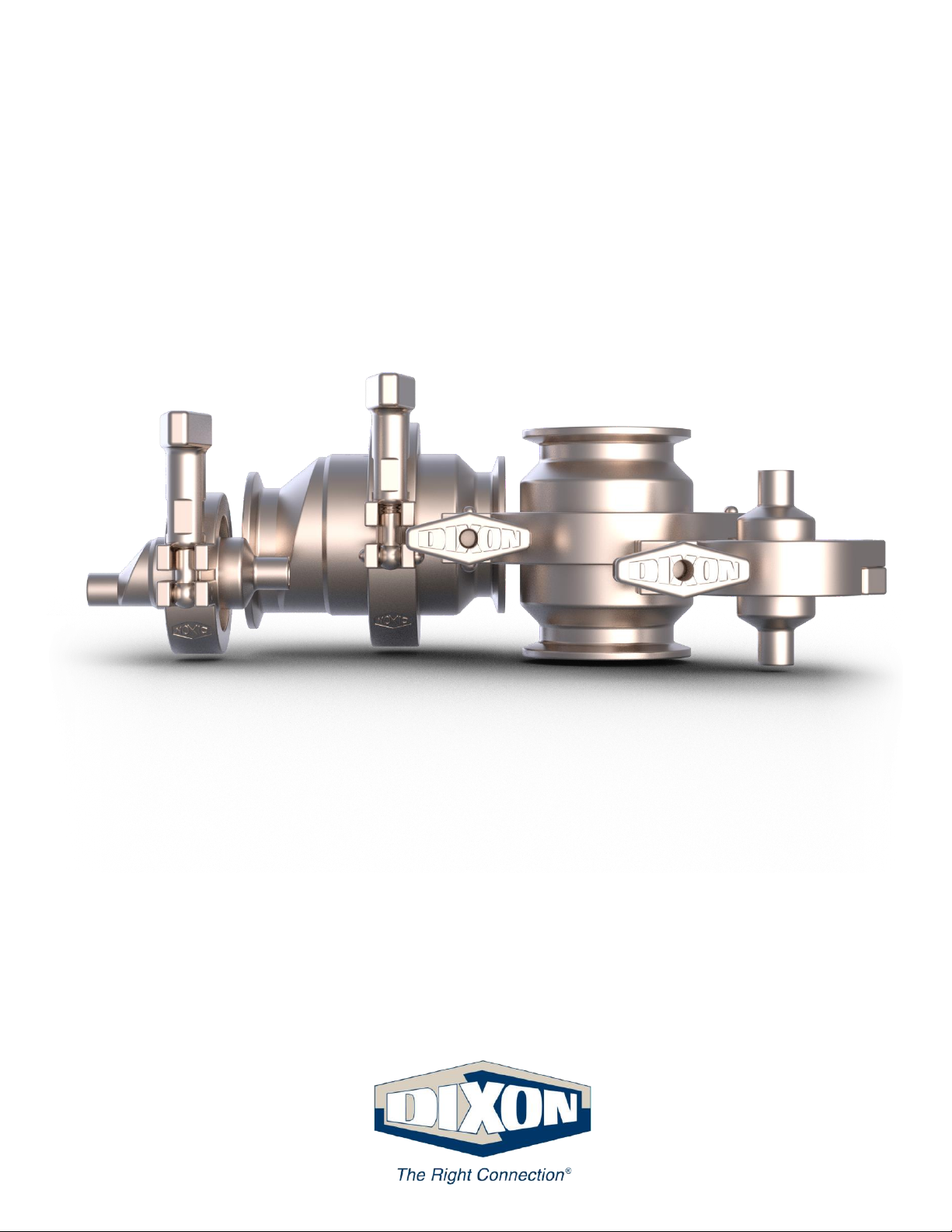
HSC and EHSC Series Spring
Check Valves
Read and understand this manual prior to
installing, operating or servicing this equipment.
Effective Date
June 2019
Page 2

2 dixonvalve.com • 800.789.1718 HSC & EHSC | IOM
Table of Contents
Safety ......................................................................................................................................................................... 3-4
Care of Stainless Steel ....................................................................................................................................................... ...5
Technical Specifications ..................................................................................................................................................... 6-7
Installation and Start-Up ..................................................................................................................................................... 8-9
Unpacking .................................................................................................................................................................... …8
Tools Needed ............................................................................................................................................................... …8
Welding ........................................................................................................................................................................ …8
Function Testing ......................................................................................................................................................................... …9
Orientation ................................................................................................................................................................... …9
Cleaning ............................................................................................................................................................................. ..10
General Maintenance ......................................................................................................................................................... ..11
Maintenance Intervals ................................................................................................................................................. ..11
Lubrication ................................................................................................................................................................... ..11
Inspection .................................................................................................................................................................... ..12
Cleaning ....................................................................................................................................................................... ..12
Assembly and Disassembly………………………………………………………………………………………………………13-15
Repair Kits……………………………………………………………………………………………………………………………...16
Bill of Materials……………………………………………………………………………………………………………………..17-22
Dimensions……………………………………………………………………………………………………………………………..23
Model Numbers and Part Numbers………………………………………………………………………………………………….24
Troubleshooting………………………………………………………………………………………………………………………..25
Certifications……………………………………………………………………………………………………………………………26
Warranty. ............................................................................................................................................................................ ...27
Page 3
3 dixonvalve.com • 800.789.1718 HSC & EHSC | IOM
Safety Information
The following DANGER, WARNING and CAUTION signs are contained in this manual. To avoid serious injury and/or possible
damage to equipment, pay attention to these messages. Hazards or unsafe practices could result in severe personal injury or death.
DANGER is used in the most extreme cases.
Hazards or unsafe practices which could result in minor or moderate injury. May also be used to alert
against an unsafe operating or maintenance practice.
Indicates a potentially hazardous situation which, if not avoided, could result in death or serious injury.
Safety logos, which appear throughout this manual, are used as a reminder that the user should carefully
review for the appropriateness of the product for the media, application and environment in which it will be
used.
Use only replacement parts and devices recommended by the manufacturer to maintain the integrity of the equipment. Make sure
the parts are properly matched to the series, model, serial number and revision level of the equipment.
Safety labels are placed on equipment where appropriate. Do not remove any labeling from any piece of equipment. Replace any
label that is missing.
DO NOT modify any Dixon Sanitary product. Non-factory modifications could create hazardous conditions and void all warranties. DO
NOT attempt to use a Dixon Sanitary product in any application that exceeds the product rating.
General Guidelines
• The owner must comply exclusively with these operating instructions and the authorized use of this piece of equipment. Should
problems arise that cannot be solved using these operating instructions, please contact Dixon® – Sanitary Division. We will be
happy to provide further assistance.
• If any modification work is performed on the product by the owner themselves, Dixon® shall no longer be considered the
manufacturer of the device. In such cases, all components must be subjected to a new certification process for any applicable
certifications that the equipment holds. Unless agreed to in writing by Dixon®, liability, warranties and guarantees shall immediately
be deemed null and void as soon as you:
o Perform modifications/conversion work on the product.
o Use the product for unauthorized purposes.
o Remove or disable safety elements.
o Process products whose material, form and size do not correspond exactly to the description provided.
o Make alterations to the original state of the device.
• The operating instructions are regarded as part of the valve.
• The operating and maintenance personnel must always be able to access the operating instructions.
• The safety instructions provided in the operating instructions must be observed.
• The operating instructions shall be valid for the entirety of the device's lifespan.
• The operating instructions must be maintained and updated as necessary.
• The operating instructions must be passed on to any subsequent owners or operators of the device.
Page 4

4 dixonvalve.com • 800.789.1718 HSC & EHSC | IOM
Safety Information
Owner Must Ensure
• The product is only used as authorized.
• The product is only used when it is in fault-free, fully functional condition, and that the safety equipment is regularly checked
to ensure that it is fully functional.
• The product is only operated, maintained and repaired by personnel with the appropriate qualifications and authorization.
• Checks are made before the product is put into operation to ensure that only the authorized person is in the work area, and no
one is in danger of being injured if the product is in operation.
• The product is checked for visual damage prior to commissioning to ensure that it is only operated when free of faults.
• Any defects are reported immediately to the appropriate supervisor.
• All safety and warning notices attached to the equipment are legible and none are removed.
• The operating instructions are always kept close to the product operation site, in a legible and complete state.
• Personnel are regularly instructed on all occupational safety and environmental protection issues, and are familiar with and
observe the operating instructions, especially the safety instructions contained herein.
• Personnel are trained and supervised to ensure that they follow safety measures, including the obligatory use of
personal protective equipment.
• The product is only connected to pipelines that are depressurized at the time of connection.
• There is no tensile or compressive stress acting on the product connections.
• There is no residual risk at any point where high pressure could occur. High pressure can cause sudden failure in or damage to
the lines and connections.
• Warning notices in the documentation for supplier modules are observed and integrated into the risk assessments in the
workplace.
Page 5

5 dixonvalve.com • 800.789.1718 HSC & EHSC | IOM
Care of Stainless Steel
The stainless-steel components in Dixon Sanitary equipment are machined, welded and assembled by skilled craftsmen using
manufacturing methods that preserve the corrosion-resistant quality of the stainless steel. Retention of corrosion-resistant qualities
under processing conditions requires regular attention to the precautions listed below.
1. Regularly check all electrical devices connected to the equipment for stray currents caused by improper
grounding, damaged insulation or other defects. Corrosion: Pitting often occurs when stray currents
encounter moist stainless steel.
2. Never leave rubber mats, fittings, wrenches, etc. in contact with stainless steel. Corrosion: Pitting or galvanic action. Objects
retard complete drying, preventing air from reforming the protective oxide film. Galvanic corrosion occurs when two dissimilar
metals touch when wet.
3. Immediately rinse equipment after use with warm water until the rinse water is clear. Clean the equipment (manual or CIP)
as soon as possible after rinsing. Corrosion: discoloration, deposits, pitting. Product deposits often cause pitting beneath the
particles.
4. Use only recommended cleaning compounds. Purchase chemicals from reputable and responsible chemical
manufacturers familiar with stainless-steel processing equipment they continuously check the effects of their products on
stainless steel.
5. Use cleaning chemicals exactly as specified by the manufacturer. Do not use excessive concentrations, temperatures or
exposure times. Corrosion: Pitting, discoloration, stress cracks. Permanent damage often occurs from excessive chemical
concentrations, temperatures or exposure times.
6. For manual cleaning, use only soft non-metallic brushes, sponges or pads. Brush with the grain on polished surfaces to avoid
scratching the surface. Corrosion: Pitting, scratches. Metal brushes or sponges will scratch the surface and promote corrosion
over a period of time. Metal particles allowed to remain on a stainless-steel surface will cause pitting.
7. Use chemical bactericides exactly as prescribed by the chemical manufacturer in concurrence with the local health authority.
Use the lowest permissible concentration, temperature and exposure time possible. Flush immediately after bacterial treatment.
In no case should the solution be in contact with stainless-steel for more than 20 minutes. Corrosion: Protective film destroyed.
Chlorine and other halogen bactericides can destroy the protective film. A few degrees increase in temperature greatly increases
chemical activity and accelerates corrosion.
8. Regularly inspect the joints in pipelines. Be sure all connections are tight fitting without binding. Corrosion: Crevice corrosion.
Small crevices caused by improperly seated gaskets will promote crevice corrosion. Stainless steel under stress will develop
stress cracking, especially in the presence of bactericides containing chlorine.
9. Regularly inspect equipment for surface corrosion (i.e. pitting deposits, stress cracks, etc.). If deposit or color corrosion is
detected, remove it immediately using mild scouring powder and detergents. Rinse thoroughly and allow to air dry. Review
production and cleaning procedures to determine the cause. Note: If corrosion is not removed, the protective film cannot be
restored, and corrosion will continue at an accelerated rate.
Page 6
6 dixonvalve.com • 800.789.1718 HSC & EHSC | IOM
Technical Specifications
Materials of Construction Technical Data
• product contact components: 316L stainless steel
• non-product contact components: CF8
Sealing Materials Technical Data
• product contact components: FKM or EPDM
Line Pressure Technical Data
• max product line pressure: 145 PSI (10 bar)
Product Temperature Technical Data
• max operating temperature: 200°F (93°C)
• minimum operating temperature: 15°F (-9°C)
Surface Finish Technical Data
• product contact components: Ra ≤ 32
• others available upon request
Connections
• clamp
• weld
• others available upon request
Seal Types
• EPDM
• FKM
Cleaning Method
• CIP – models: HSC & EHSC sizes: 1 inch – 4 inch
• COP – models: HSC & EHSC sizes: 0.5 inch – 0.75 inch
Page 7
7 dixonvalve.com • 800.789.1718 HSC & EHSC | IOM
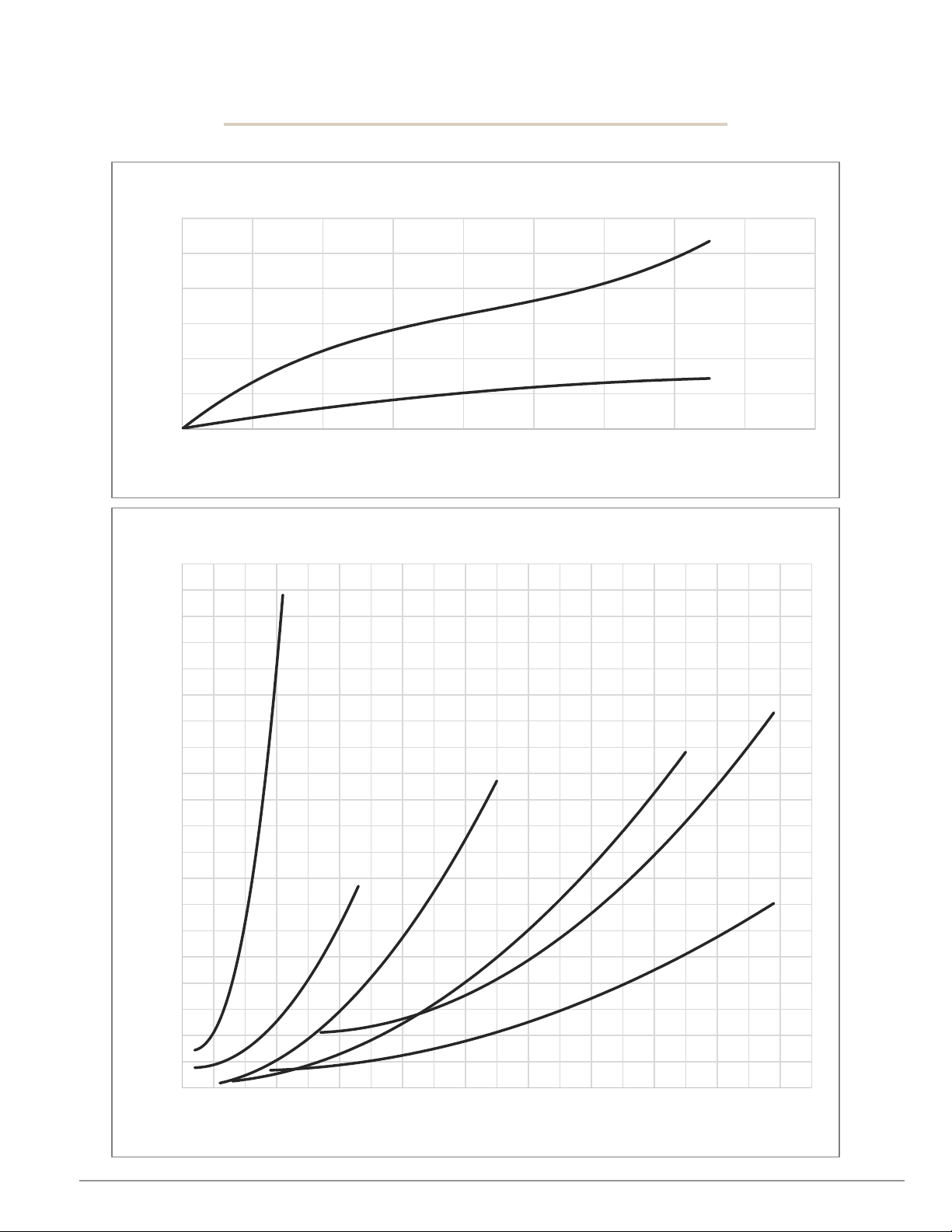
Pressure Drop Charts
HSC & EHSC Series Spring Check Valves
0
10
20
30
40
50
60
0 2 4 6 8 10 12 14 16 18
PRESSURE DROP (PSI)
FLOW RATE (GPM)
0.5 inch - 0.75 inch
0.75"
0.50"
0
1
2
3
4
5
6
7
8
9
10
11
12
13
14
15
16
17
18
19
20
0 25 50 75 100 125 150 175 200 225 250 275 300 325 350 375 400 425 450 475 500
PRESSURE DROP (PSI)
FLOW RATE (GPM)
1 inch - 4 inch
3.0"
1.0"
1.5"
2.0"
4.0"
2.5"
Page 8

8 dixonvalve.com • 800.789.1718 HSC & EHSC | IOM
Installation & Start-Up
The following should be performed upon receiving the product and prior to installation and use of the product. It is important that all
the following processes and procedures are carefully followed and adhered to. Dixon® is not responsible for any damage that
occurs during the unpacking or installation process.
Unpacking
Carefully unpack all the parts and inspect each part for any damage that may have occurred during shipment. Report any damage to
the carrier immediately. The ports on the valve are protected with a plastic cover. If any covers are missing or damaged, inspect the
ports on the valve thoroughly for any damage. Certificates and additional information for the valve can be found at dixonvalve.com.
Please add any necessary paperwork to the plant maintenance files for future use and reference.
Tools Needed
The following tools may be required for any maintenance of the product:
• O-ring pick
• screwdriver
Welding
• For equipment delivered with weld end connections, any rubber or plastic components MUST be removed from the equipment
prior to welding. (See assembly instructions for proper removal of such components.)
• Follow all necessary safety precautions, check lists and standard procedures prior to performing any welding on the equipment.
• Weld the equipment into the process line, being sure to follow and comply with appropriate industry welding procedures and
standards. For equipment used in food, beverage or dairy applications that carries 3A® certification, see 3A® standard 00-01-2018
section E1.1.1 for proper procedure and requirements.
• Re-assemble the equipment per the assembly section of this manual.
• Check the equipment for proper operation and perform leak test if necessary.
Page 9
9 dixonvalve.com • 800.789.1718 HSC & EHSC | IOM
Installation & Start-Up
Function Testing
The information provided in this manual is intended to be used as a guide for proper functionality. Before installation, test the equipment
under the specific conditions of the application in a safe, controlled environment. Variations in application conditions can cause equipment
to fail, even though it passed an initial test.
□ Check visually to ensure that the equipment is not leaking.
□ Any defective seal that could have been damaged during disassembly or assembly must be replaced.
□ Check all equipment components for any signs of damage and replace damaged components.
□ Ensure that all screw fittings are tight if applicable.
□ Ensure that any pneumatic hose connections are free of leaks if applicable.
□ Confirm all pipes and fittings connected to the equipment permitted for use are in the intended pressure range.
□ Confirm all electrical installations are protected sufficiently and in accordance with appropriate safety standards if applicable.
□ Check that the maximum pressure indicated on the equipment or in the specifications section of this manual has been complied
with.
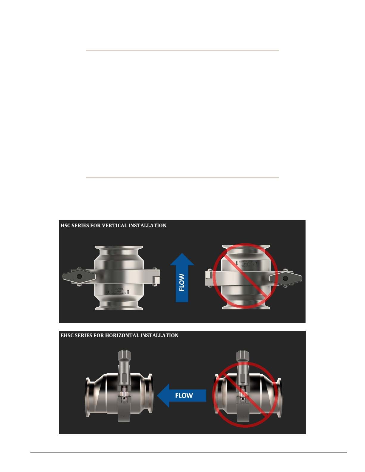
Installation Orientation
Equipment must be installed in the proper orientation to ensure proper functionality and cleanability. Please refer to the following
diagrams below for proper installation.
Page 10

10 dixonvalve.com • 800.789.1718 HSC & EHSC | IOM
Cleaning
IMPORTANT: Before operating the equipment during formal production, please follow the guidelines listed below to ensure that your
equipment is clean and ready for service.
• Ensure that the equipment is installed in a proper orientation to allow the equipment to be cleaned and drained
properly. Reference the installation and startup section of the manual for orientation guidelines.
• Flush the equipment with an appropriate cleaning agent to remove any residue that may be on the equipment from
shipping. IMPORTANT: DO NOT use cleaning agents that will attack stainless steel or the elastomers that were supplied
with the valve. If you are unsure what elastomer is used in the valve, reference the part number key in this manual to make
the determination.
• Follow any MSDS instructions for proper use or handling of cleaning agents.
• Flush the equipment sufficiently to remove any soiling from the product contact components. Depending on the process,
there may be varying amounts of soiling. Cleaning times and cleaning agent concentrations will vary depending on the
product being processed. It is the responsibility of the operator to determine and adjust these cleaning specifications as
necessary.
• The equipment should not be allowed to sit with product present in it for extended periods of time. Equipment should be
cleaned immediately after processing is complete.
Page 11

11 dixonvalve.com • 800.789.1718 HSC & EHSC | IOM
General Maintenance
To ensure proper operation of your Dixon® equipment, proper maintenance must be performed at regular intervals. To prevent
damage, check all fitting connections and screw connections for any loosening of the connections during equipment operation.
Maintain adequate spare parts stock for all replacement components on the piece of equipment. Please refer to the repair kits section
of the manual for complete component part numbers and kit part numbers.
Servicing Intervals
Recommended intervals for one shift operation would be 3 months. However, only the user/owner can determine the appropriate
service intervals as the length between service intervals is dependent on the following parameters:
• duration of use per day – number of cycles
• type of product
• product temperature
• product viscosity
• cleaning agent
• type of cleaning (CIP/SIP/COP)
Lubrication
Please use the following chart below for proper grease type for varying component materials. DO NOT use mineral or animalproduct-based greases. Check all visible seals for any signs of damage and replace as necessary. For sliding surfaces, use Jax
®
PurGel Klear food grade grease. If a different grease is used other than what is specified in this manual, there is risk of damaging the
seals. Lubrication is only required when the equipment is being reassembled after servicing.
Seal Material
Grease Type
EPDM
JAX® PurGel Klear
FKM
JAX® PurGel Klear
Page 12

12 dixonvalve.com • 800.789.1718 HSC & EHSC | IOM
General Maintenance
Inspection
Inspection of all components listed below should be done during regular servicing intervals. Before removing the equipment from the
process line, please take care to do the following:
• Clean the process line completely to remove any product that may be harmful if contacting a person.
• Drain the process line completely that connects to the equipment being serviced.
• Close any isolation valves on either side of the equipment being serviced.
• Once the equipment has been removed from the line, cap the lines that were connected to the piece of equipment being
serviced to prevent any foreign material from entering the line.
Any components that show signs of severe wear or damage should be replaced during the scheduled maintenance time for the
equipment. Please refer to the assembly and disassembly section of this manual for proper instructions on removing and replacing
any worn or damaged components. Replacement components and repair kits can be found in the BOM or repair kits section of this
manual.
Manual Cleaning (COP)
1. Refer to the disassembly section of the manual and follow instructions to remove all product contact components.
2. Inspect the product contact components of the equipment for any signs of possible damage. Replace components as necessary.
(See the equipment BOM in this manual for replacement component part numbers.)
3. Clean all surfaces of the product contact components by manually brushing in a bath of cleaning solution (acid detergents or
simple alkaline soda type detergents).
4. After cleaning, rinse all components thoroughly with water.
5. Refer to the assembly section of the manual and follow instructions to properly reassemble the equipment.
Cleaning in Place (CIP)
Note: Not all models or sizes may be certified for CIP. Please check the specifications section of the manual to determine what
cleaning method is suitable.
1. Refer to the disassembly section of the manual and follow instructions to remove all product contact components.
2. Regularly flush the valve with a suitable medium to preserve seals and integrity of the product contact surfaces, such as when
there is a product changeover or downtime. These intervals shall be determined by the end user.
3. Important: Only use cleaning agents which will not harm the seals and stainless-steel.
4. Follow any MSDS instructions for proper use or handling of cleaning agents.
5. The necessary cleaning times, temperatures and cleaning agents will depend on the degree of contamination and must
be adapted accordingly.
6. Cleaning flow velocities of 5-6 ft/s should be maintained for proper cleaning of the equipment.
7. After cleaning, rinse the equipment thoroughly with water.
8. Refer to the assembly section of the manual and follow instructions to properly reassemble the equipment.
Page 13

13 dixonvalve.com • 800.789.1718 HSC & EHSC | IOM
Assembly and Disassembly
For disassembly, follow the appropriate assembly instructions, in reverse.
To ensure quality operation of your Dixon® equipment, the equipment must be disassembled and assembled properly to prevent
equipment damage during operation. Please follow the instructions contained in this manual carefully and be sure to follow any safety
warnings contained herein. If any questions should arise during the assembly or disassembly process that are not addressed in this
manual, please feel free to contact Dixon® – Sanitary Division at 800.789.1718.
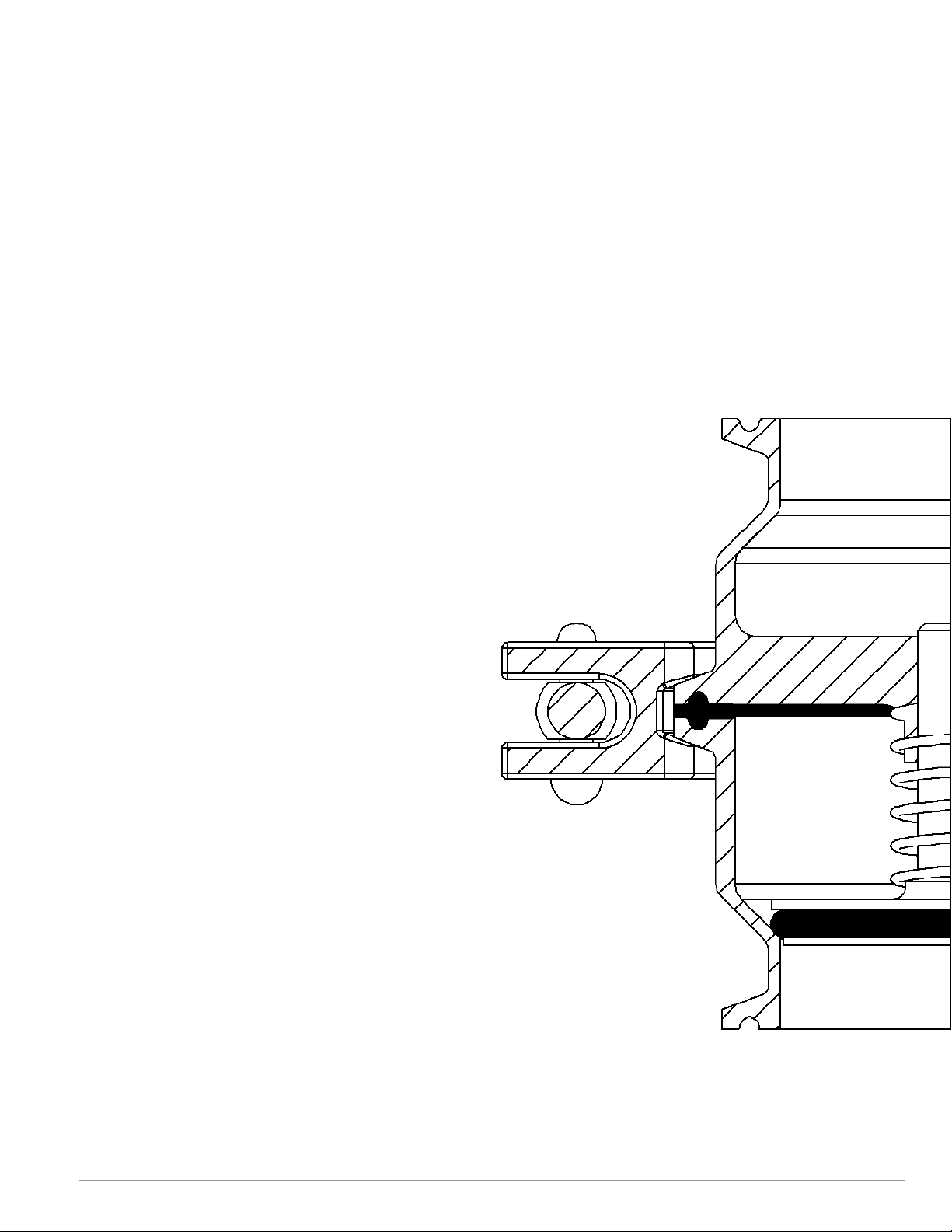
Assembly (0.5 inch - 0.75 inch HSC)
All images shown are for illustration purposes only. Actual product may vary due to differences between size and series.
1
2
Install plunger O-ring onto plunger and set
into lower body. Slide spring onto plunger.
3
Place spider O-ring, spider plate, and body
gasket onto upper body. Ensure proper
orientation of spider plate.
4
Set upper body assembly down onto
plunger and lower body. Hold together.
5
Install body clamp and tighten to 25 in-lb.
6
Assembly (0.5 inch - 0.75 inch EHSC)
Page 14

14 dixonvalve.com • 800.789.1718 HSC & EHSC | IOM
All images shown are for illustration purposes only. Actual product may vary due to differences between size and series.
1
2
Install plunger O-ring onto plunger and set
into lower body. Slide spring onto plunger.
3
Place spider O-ring, spider plate, and body
gasket onto upper body. Ensure proper
orientation of spider plate.
4
Set upper body assembly down onto
plunger and lower body. Hold together.
5
Install body clamp and tighten to 25 in-lb.
6
Assembly (1 inch EHSC)
All images shown are for illustration purposes only.
1
2
Install plunger O-ring onto plunger and set
into lower body. Slide spring onto plunger.
3
Clamp together upper body assembly and
tighten to 25 in-lb. Ensure proper alignment
of bodies.
4
Slide upper body assembly onto plunger
and lower body. Hold together.
5
Install second body clamp. Tighten to 25 inlb.
6
unobstructed flow
Page 15

15 dixonvalve.com • 800.789.1718 HSC & EHSC | IOM
Assembly (1 inch – 4 inch HSC | 1.5 inch – 4 inch EHSC)
All images shown are for illustration purposes only. Actual product may vary due to differences between size and series.
1
2
Install plunger O-ring onto plunger and set
into lower body. Slide spring onto plunger.
3
Set body gasket onto lower body.
4
Slide upper body onto plunger and lower
body. Hold together.
5
Install body clamp. Tighten to 25 in-lb.
6
Page 16

16 dixonvalve.com • 800.789.1718 HSC & EHSC | IOM
Repair Kits
To ensure proper operation of your Dixon® equipment, proper maintenance must be performed at regular intervals. To prevent damage
and improper operation, use only genuine replacement parts and kits offered by Dixon® to maintain the integrity of the equipment. Make
sure the parts are properly matched to the series, model, serial number and revision level of the equipment. Please see the list of kits
below offered for this piece of equipment:
Series
Elastomer
Size
Part Number
HSC
EPDM
0.5 inch
HSC-RKE050
0.75 inch
HSC-RKE075
1 inch
HSC-RKE100
1.5 inch
HSC-RKE150
2 inch
HSC-RKE200
2.5 inch
HSC-RKE250
3 inch
HSC-RKE300
4 inch
HSC-RKE400
FKM
0.5 inch
HSC-RKV050
0.75 inch
HSC-RKV075
1 inch
HSC-RKV100
1.5 inch
HSC-RKV150
2 inch
HSC-RKV200
2.5 inch
HSC-RKV250
3 inch
HSC-RKV300
4 inch
HSC-RKV400
EHSC
EPDM
0.5 inch
EHSC-RKE050
0.75 inch
EHSC-RKE075
1 inch
EHSC-RKE100
1.5 inch
EHSC-RKE150
2 inch
EHSC-RKE200
2.5 inch
EHSC-RKE250
3 inch
EHSC-RKE300
4 inch
EHSC-RKE400
FKM
0.5 inch
EHSC-RKV050
0.75 inch
EHSC-RKV075
1 inch
EHSC-RKV100
1.5 inch
EHSC-RKV150
2 inch
EHSC-RKV200
2.5 inch
EHSC-RKV250
3 inch
EHSC-RKV300
4 inch
EHSC-RKV400
0.5 inch & 0.75 inch HSC & EHSC Repair Kit
Contains: body gasket (5), spider O-ring (7), and plunger
O-ring (2)
1 inch EHSC Repair Kit
Contains: two body gaskets (5) and plunger O-ring (2)
1 inch – 4 inch HSC & 1.5 inch – 4 inch EHSC
Contains: body gasket (5) and plunger O-ring (2)
Page 17

17 dixonvalve.com • 800.789.1718 HSC & EHSC | IOM
Bill of Materials
ITEM
PART NO.
DESCRIPTION
MATERIAL
QTY.
0.5 INCH CONCENTRIC SPRING CHECK VALVE
1
HSC-LB050
LOWER BODY
316L SS
1
2
-PART OF REPAIR KIT-
1
3
HSC-P050
PLUNGER
316L SS
1
4
HSC-SP050
SPRING
1
5
-PART OF REPAIR KIT-
1
6
HSC-S050
SPIDER
316L SS
1
7
-PART OF REPAIR KIT-
1
8
13MHHM100-150
CLAMP
CF8
1
9
HSC-UB050
UPPER BODY
316L SS
1
0.75 INCH CONCENTRIC SPRING CHECK VALVE
1
HSC-LB075
LOWER BODY
316L SS
1
2
-PART OF REPAIR KIT-
1 3 HSC-P075
PLUNGER
316L SS
1
4
HSC-SP075
SPRING
1
5
-PART OF REPAIR KIT-
1 6 HSC-S075
SPIDER
316L SS
1
7
-PART OF REPAIR KIT-
1
8
13MHHM100-150
CLAMP
CF8
1 9 HSC-UB075
UPPER BODY
316L SS
1
Page 18

18 dixonvalve.com • 800.789.1718 HSC & EHSC | IOM
ITEM
PART NO.
DESCRIPTION
MATERIAL
QTY.
0.5 INCH ECCENTRIC SPRING CHECK VALVE
1
HSC-LB050
LOWER BODY
316L SS
1
2
-PART OF REPAIR KIT-
1
3
HSC-P050
PLUNGER
316L SS
1
4
HSC-SP050
SPRING
1
5
-PART OF REPAIR KIT-
1
6
HSC-S050
SPIDER
316L SS
1
7
-PART OF REPAIR KIT-
1
8
13MHHM100-150
CLAMP
CF8
1
9
EHSC-UB050
UPPER BODY
316L SS
1
0.75 INCH ECCENTRIC SPRING CHECK VALVE
1
HSC-LB075
LOWER BODY
316L SS
1
2
-PART OF REPAIR KIT-
1 3 HSC-P075
PLUNGER
316L SS
1
4
HSC-SP075
SPRING
1
5
-PART OF REPAIR KIT-
1 6 HSC-S075
SPIDER
316L SS
1
7
-PART OF REPAIR KIT-
1
8
13MHHM100-150
CLAMP
CF8
1 9 EHSC-UB075
UPPER BODY
316L SS
1
Page 19

19 dixonvalve.com • 800.789.1718 HSC & EHSC | IOM
ITEM
PART NO.
DESCRIPTION
MATERIAL
QTY.
1 INCH ECCENTRIC SPRING CHECK VALVE
1
HSC-LB100
LOWER BODY
316L SS
1
2
-PART OF REPAIR KIT-
1
3
HSC-P100
PLUNGER
316L SS
1
4
HSC-SP100
SPRING
1
5
-PART OF REPAIR KIT-
1
6
13MHHM100-150
CLAMP
CF8
1
7
EHSC-UB100
UPPER BODY (2 PC)
316L SS
1
Page 20

20 dixonvalve.com • 800.789.1718 HSC & EHSC | IOM
Page 21

21 dixonvalve.com • 800.789.1718 HSC & EHSC | IOM
ITEM
PART NO.
DESCRIPTION
MATERIAL
QTY.
1 INCH - 4 INCH CONCENTRIC SPRING CHECK VALVE
1
HSC-LB100
1 INCH LOWER BODY, CLAMP
316L SS
1
HSC-LB100B
1 INCH LOWER BODY, WELD
HSC-LB150
1.5 INCH LOWER BODY, CLAMP
HSC-LB150B
1.5 INCH LOWER BODY, WELD
HSC-LB200
2 INCH LOWER BODY, CLAMP
HSC-LB200B
2 INCH LOWER BODY, WELD
HSC-LB250
2.5 INCH LOWER BODY, CLAMP
HSC-LB250B
2.5 INCH LOWER BODY, WELD
HSC-LB300
3 INCH LOWER BODY, CLAMP
HSC-LB300B
3 INCH LOWER BODY, WELD
HSC-LB400
4 INCH LOWER BODY, CLAMP
HSC-LB400B
4 INCH LOWER BODY, WELD
2
-PART OF REPAIR KIT-
1 3 HSC-P100
1 INCH PLUNGER
316L SS
1
HSC-P150
1.5 INCH PLUNGER
HSC-P200
2 INCH PLUNGER
HSC-P250
2.5 INCH PLUNGER
HSC-P300
3 INCH PLUNGER
HSC-P400
4 INCH PLUNGER
4
HSC-SP100
1 INCH SPRING
316L SS
1
HSC-SP150
1.5 INCH SPRING
HSC-SP200
2 INCH SPRING
HSC-SP250
2.5 INCH SPRING
HSC-SP300
3 INCH SPRING
HSC-SP400
4 INCH SPRING 5 -PART OF REPAIR KIT-
1
6
13MHHM100-150
1 INCH CLAMP
CF8
1
13MHHM200
1.5 INCH CLAMP
13MHHM250
2 INCH CLAMP
13MHHV300
2.5 INCH CLAMP
13MHHM400
3 INCH CLAMP
13MHHM500
4 INCH CLAMP
7
HSC-UB100
1 INCH LOWER BODY, CLAMP
316L SS
1
HSC-UB100B
1 INCH LOWER BODY, WELD
HSC-UB150
1.5 INCH LOWER BODY, CLAMP
HSC-UB150B
1.5 INCH LOWER BODY, WELD
HSC-UB200
2 INCH LOWER BODY, CLAMP
HSC-UB200B
2 INCH LOWER BODY, WELD
HSC-UB250
2.5 INCH LOWER BODY, CLAMP
HSC-UB250B
2.5 INCH LOWER BODY, WELD
HSC-UB300
3 INCH LOWER BODY, CLAMP
HSC-UB300B
3 INCH LOWER BODY, WELD
HSC-UB400
4 INCH LOWER BODY, CLAMP
HSC-UB400B
4 INCH LOWER BODY, WELD
Page 22

22 dixonvalve.com • 800.789.1718 HSC & EHSC | IOM
ITEM
PART NO.
DESCRIPTION
MATERIAL
QTY.
1.5 INCH - 4 INCH ECCENCENTRIC SPRING CHECK VALVE
1
HSC-LB150
1.5 INCH LOWER BODY, CLAMP
316L SS
1
HSC-LB150B
1.5 INCH LOWER BODY, WELD
HSC-LB200
2 INCH LOWER BODY, CLAMP
HSC-LB200B
2 INCH LOWER BODY, WELD
HSC-LB250
2.5 INCH LOWER BODY, CLAMP
HSC-LB250B
2.5 INCH LOWER BODY, WELD
HSC-LB300
3 INCH LOWER BODY, CLAMP
HSC-LB300B
3 INCH LOWER BODY, WELD
HSC-LB400
4 INCH LOWER BODY, CLAMP
HSC-LB400B
4 INCH LOWER BODY, WELD
2
-PART OF REPAIR KIT-
1
3
HSC-P150
1.5 INCH PLUNGER
316L SS
1
HSC-P200
2 INCH PLUNGER
HSC-P250
2.5 INCH PLUNGER
HSC-P300
3 INCH PLUNGER
HSC-P400
4 INCH PLUNGER
4
HSC-SP150
1.5 INCH SPRING
316L SS
1
HSC-SP200
2 INCH SPRING
HSC-SP250
2.5 INCH SPRING
HSC-SP300
3 INCH SPRING
HSC-SP400
4 INCH SPRING
5
-PART OF REPAIR KIT-
1 6 13MHHM200
1.5 INCH CLAMP
CF8
1
13MHHM250
2 INCH CLAMP
13MHHV300
2.5 INCH CLAMP
13MHHM400
3 INCH CLAMP
13MHHM500
4 INCH CLAMP
7
HSC-UB150
1.5 INCH LOWER BODY, CLAMP
316L SS
1
HSC-UB150B
1.5 INCH LOWER BODY, WELD
HSC-UB200
2 INCH LOWER BODY, CLAMP
HSC-UB200B
2 INCH LOWER BODY, WELD
HSC-UB250
2.5 INCH LOWER BODY, CLAMP
HSC-UB250B
2.5 INCH LOWER BODY, WELD
HSC-UB300
3 INCH LOWER BODY, CLAMP
HSC-UB300B
3 INCH LOWER BODY, WELD
HSC-UB400
4 INCH LOWER BODY, CLAMP
HSC-UB400B
4 INCH LOWER BODY, WELD
Page 23

23 dixonvalve.com • 800.789.1718 HSC & EHSC | IOM
Dimensions
Dimensions are approximate and subject to change without notice. Contact sanitarydrawings@dixonvalve.com for specific drawing related requests.
HSC
EHSC
Size
A (inches)
HSC
EHSC
0.5 inch
2.7
3.1
0.75 inch
2.7
3.1
1 inch
3.3
4.0
1.5 inch
3.4
3.6
2 inch
3.4
4.1
2.5 inch
3.4
4.0
3 inch
3.4
4.0
4 inch
4.1
4.7
Page 24

24 dixonvalve.com • 800.789.1718 HSC & EHSC | IOM
Part Number Key
To ensure proper specification of your Dixon® product, below is the complete part number key to configure the product with the
options that meet your specific requirements. If you require an option that is not listed in this key, please feel free to contact Dixon® –
Sanitary Division at 800.789.1718.
Page 25

25 dixonvalve.com • 800.789.1718 HSC & EHSC | IOM
Troubleshooting
Problem
Possible Cause
Suggested Action
Fluid is leaking past plunger seal
Damage to plunger O-ring
Inspect and replace plunger O-ring
Damage to spring
Inspect and replace spring
Obstruction between plunger and
body or in the spring
Inspect for obstructions and replace components if
necessary
Valve is leaking between upper body
and lower body
Damage to the body gasket
Inspect and replace body gasket
Valve is not stroking properly
Obstruction between plunger and
body or in the spring
Inspect for obstructions and replace components if
necessary
Fluid not flowing through valve
Valve is installed improperly
Check installation section to make sure fluid is flowing
into inlet of valve
Any other issue
-
Contact Dixon Sanitary 800.789.1718
Page 26

26 dixonvalve.com • 800.789.1718 HSC & EHSC | IOM
Certificates
Dates shown on certificate may not be current.
Page 27

27 dixonvalve.com • 800.789.1718 HSC & EHSC | IOM
Limited Warranty
DIXON VALVE AND COUPLING COMPANY (herein called "Dixon") warrants the products described herein and manufactured by
Dixon to be free from defects in material and workmanship for a period of one (1) year from date of shipment by Dixon under normal
use and service. Its sole obligation under this warranty being limited to repairing or replacing, as hereinafter provided, at its option
any product found to Dixon's satisfaction to be defective upon examination by it, provided that such product shall be returned for
inspection to Dixon's factory within three (3) months after discovery of the defect. The repair or replacement of defective products
will be made without charge for parts or labor. This warranty shall not apply to: (a) parts or products not manufactured by Dixon,
the warranty of such items being limited to the actual warranty extended to Dixon by its supplier; (b) any product that has been
subject to abuse, negligence, accident, or misapplication; (c) any product altered or repaired by others than Dixon; and (d) to normal
maintenance services and the replacement of service items (such as washers, gaskets and lubricants) made in connection with
such services. To the extent permitted by law, this limited warranty shall extend only to the buyer and any other person reasonably
expected to use or consume the goods who is injured in person by any breach of the warranty. No action may be brought against
Dixon for an alleged breach of warranty unless such action is instituted within one (1) year from the date the cause of action accrues.
This limited warranty shall be construed and enforced to the fullest extent allowable by applicable law.
Other than the obligation of Dixon set forth herein, Dixon disclaims all warranties, express or implied, including but not limited to any
implied warranties of merchantability or fitness for a particular purpose, and any other obligation or liability. The foregoing constitutes
Dixon's sole obligation with respect to damages, whether direct, incidental or consequential, resulting from the use or performance of
the product.
Some products and sizes may be discontinued when stock is depleted or may require a minimum quantity for ordering
Page 28

© 2017 DVCC Printed in the USA DS_IOmanual_HSC & EHSC 05/19
Dixon, founded in 1916, is a premier manufacturer and supplier
of hose couplings, valves, dry-disconnects, swivels, and other
fluid transfer and control products. The company’s global reach
includes a wide range of products for numerous industries
including petroleum exploration, refining, transportation, chemical
processing, food & beverage, steel, fire protection, construction,
mining and manufacturing. Dixon’s strategic objective is to
create solutions that make products safer, leak-free, longer
lasting, and always available.
Dixon Sanitary
N25 W23040 Paul Road • Pewaukee, WI 53072
Customer Service: 800.789.1718
sanitarysales@dixonvalve.com
Fax: 800.789.4046
dixonvalve.com
 Loading...