

Dixon D149P21 Repair Parts Manual
LIMITED WARRANTY
The Manufacturer warrants to the original consumer purchaser that this product as
manufactured is free from defects in materials and workmanship. For a period of
three (3) years from date of purchase by the original consumer purchaser, we will
repair or replace, at our option, without charge for parts or labor incurred in replacing parts, any part which we fi nd to be defective due to materials or work man ship.
This Warranty is subject to the following limitations and exclusions.
1. This warranty does not apply to the engine, transaxle/transmission components,
battery (except as noted below) or com po nents parts thereof. Please refer to the
applicable manufacturer's warranty on these items.
2. Transportation charges for the movement of any power equipment unit or at tach ment are the responsibility of the purchaser. Transportation charges for any
parts sub mit ted for replacement under this warranty must be paid by the purchaser unless such return is requested by the manufacturer.
3. Battery Warranty: On products equipped with a Battery, we will replace, without
charge to you, any battery which we fi nd to be defective in manufacture, during
the fi rst ninety (90) days of ownership. After ninety (90) days, we will exchange
the Battery, charging you 1/12 of the price of a new Battery for each full month
from the date of the original sale. Battery must be maintained in accordance with
the in struc tions furnished.
4. The Warranty period for any products used for rental or commercial purposes is
limited to 45 days from the date of original purchase.
5. This Warranty applies only to products which have been properly assembled,
adjusted, operated, and maintained in accordance with the instructions fur nished.
This Warranty does not apply to any product which has been subjected to al ter ation, misuse, abuse, improper assembly or installation, delivery damage, or to
normal wear of the product.
6. Exclusions: Excluded from this Warranty are belts, blades, blade adapters, normal wear, normal adjustments, standard hardware and normal maintenance.
7. In the event you have a claim under this Warranty, you must return the product to
an authorized service dealer.
Should you have any unanswered questions concerning this Warranty, contact:
giving the model number, serial number and date of purchase of your product and
the name and address of the au tho rized dealer from whom it was pur chased.
THIS WARRANTY DOES NOT APPLY TO INCIDENTAL OR CONSEQUENTIAL
DAMAGES AND ANY IMPLIED WAR RAN TIES ARE LIMITED TO THE SAME
TIME PERIODS STATED HEREIN FOR OUR EXPRESSED WARRANTIES.
Some areas do not allow the limitation of consequential damages or lim i ta tions
of how long an implied Warranty may last, so the above lim i ta tions or exclusions
may not apply to you. This Warranty gives you specifi c legal rights, and you may
have other rights which vary from locale to locale.
This is a limited Warranty within the meaning of that term as defi ned in the
Magnuson-Moss Act of 1975.
In Canada contact:
HOP
Customer Service Department
5855 Terry Fox Way
Mississauga, Ontario L5V 3E4
HOP
Customer Service Department
9335 Harris Corners Parkway
Charlotte, NC 28269 USA
REPAIR PARTS MANUAL
MODEL NUMBER D149P21
(MFG. ID. NO. 96132008300)
Rotary Lawn Mower
For Parts and Service or Technical Assistance, call 1-800-487-5951
581 91 86-27 12.03.12 BY Printed in U.S.A.
NOTE: Gasoline containing up to 10% ethanol (E10) is acceptable for use in this machine.
The use of any gasoline exceeding 10% ethanol (E10) will void the product warranty.
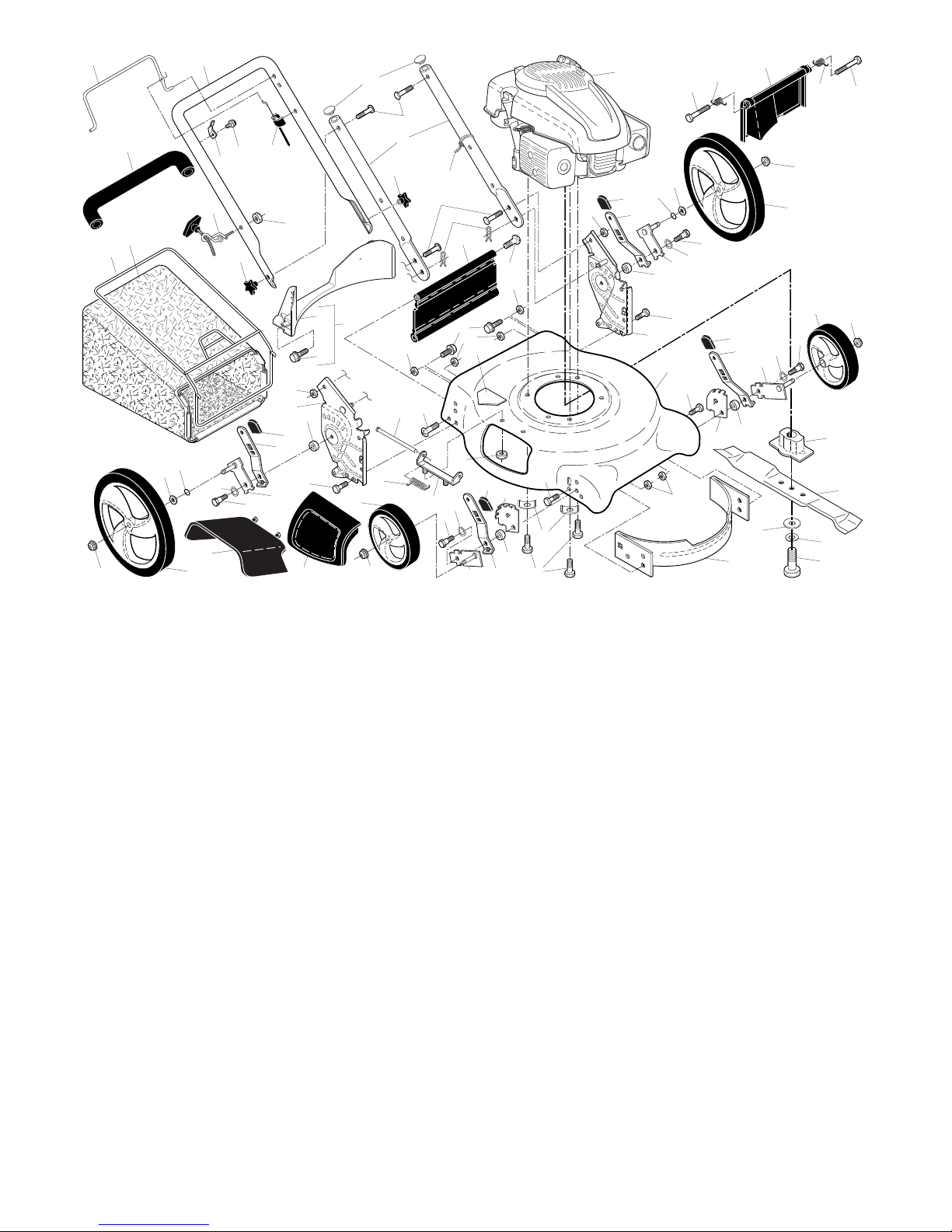
DIXON ROTARY LAWN MOWER - MODEL NUMBER D149P21 (MFG. ID. NO. 96132008300)
12
68
13
4
50
40
14
12
11
5
87
14
6
3
7
88
15
21
41
47
89
59
33
32
66
30
65
34
44
36
73
2
39
65
66
49
31
73
36
48
32
89
26
33
10
30
8
76
77
75
37
61
58
51
47
41
18
35
46
62
33
9
73
36
20
22
84
29
74
30
45
8
25
52
84
28
35
43
33
83
22
30
55
19
23
73
39
49
36
37
42
44
61
57
56
54
53
DIXON ROTARY LAWN MOWER - MODEL NUMBER D149P21 (MFG. ID. NO. 96132008300)
KEY PART
NO. NO. DESCRIPTION
1 532 19 60-25 Control Bar
2 581 91 76-01 Upper Handle Assembly
(Includes Foam Grip)
3 580 63 86-02 Bar, Lower Handle
4 532 19 47-88 Rope Guide
5 532 13 20-04 Nut, Hex
6 532 19 15-74 Handle Bolt
7 532 06 64-26 Wire Tie
8 874 78 05-12 Bolt, Hex Head
5/16-18 x 3/4
9 532 15 41-32 Hinge Bracket
10 532 16 57-54 Mulcher Door
11 532 44 09-34 Engine Zone Control Cable
3
12 532 17 88-48 Hex Washer Head Screw
#10-16 x 5/8
13 532 43 00-34 Up-Stop Bracket
14 532 18 23-98 Handle Knob
15 532 05 17-93 Hairpin Cotter
18 817 60 04-06 Screw
19 532 40 66-89 Axle Arm Assy., Front, LH
20 532 40 66-90 Axle Arm Assy., Front, RH
21 532 41 86-55 Kit, Rear Skirt
22 532 40 64-28 Selector Spring, Front
23 532 41 06-03 Rear Door Assembly
25 580 91 56-02 Handle Bracket, LH
26 580 91 57-02 Handle Bracket, RH
28 532 41 44-41 Wheel Adjusting Bracket,
Front, LH
29 532 41 44-40 Wheel Adjusting Bracket,
Front, RH
IMPORTANT: Use only Original Equipment Manufacturer (O.E.M.) replacement parts. Failure to do so could be hazardous, damage your lawn mower and void your warranty.
NOTE: All component dimensions given in U.S. inches. 1 inch = 25.4 mm.
KEY PART
NO. NO. DESCRIPTION
30 532 40 16-29 Spacer
31 532 16 57-60 Discharge Defl ector
32 532 44 15-59 Selector Spring, Rear
33 532 70 10-37 Selector Knob
34 532 41 06-00 Axle Arm Assy., Rear, LH
35 532 42 65-89 Locknut, Hex 5/16-18
36 532 40 16-38 Shoulder Bolt 5/16-18
37 532 19 70-25 Wheel & Tire Assembly,
Front 8 x 1-3/4
39 532 40 91-49 Nut, Hex
40 532 41 19-49 Frame, Grassbag
41 532 19 41-86 Screw, Hinge
42 532 40 54-21 Spring, LH
43 532 40 54-23 Spring, RH
44 532 18 41-93 Bolt, Rear Door
45 532 15 04-06 Hex Head Thread Rolling
Screw 3/8-16 x 1
46 532 40 47-63 Danger Decal
47 532 75 11-53 Nut, Hex
48 532 41 06-01 Axle Arm Assy., Rear, RH
49 532 43 31-21 Wheel & Tire Assembly,
Rear 12 x 1-3/4
50 581 00 21-01 Grassbag
51 532 14 72-86 Hinge Rod
52 581 70 83-16 Kit, Housing (Includes #46)
53 532 85 10-84 Screw, Hex Head, Grade 8
3/8-24 x 1-3/8
54 532 85 02-63 Helical Lockwasher
55 532 85 10-74 Hardened Washer
KEY PART
NO. NO. DESCRIPTION
56 532 40 67-12 21" Blade
57 532 41 83-73 Blade Adapter
58 532 15 21-24 Hinge Spring
59 - - - Engine, Kohler, Model
Number XT650-3018
(For engine service and
replacement parts, call
Kohler at 1-800-544-2444)
61 532 40 91-48 Flanged Locknut
62 873 80 04-00 Nut, Hex
65 532 08 83-48 Washer, Flat
66 532 19 74-80 O-Ring
68 532 18 63-62 Grip, Foam
73 532 40 16-30 Washer, Curved, Cylindrical
74 532 12 50-78 Washer, Special, Engine
75 532 41 36-93 Kit, Rear Baffl e
(Includes 3 Screws)
76 532 41 05-89 Baffl e, Rear
77 817 41 13-12 Screw, Rear Baffl e
83 532 42 85-01 Baffl e, Front
84 817 00 05-10 Screw, Hex Head 5/8-16
87 532 43 75-16 Plug, Handle Bar
88 872 25 05-05 Bolt, Carriage
89 873 97 05-00 Nut, Hex
- - 532 40 47-64 Warning Decal (not shown)
- - 532 19 37-32 Operator’s Manual, English
- - 532 19 37-34 Operator’s Manual, French
- - 532 19 37-35 Operator’s Manual, Spanish
- - 581 91 86-27 Repair Parts Manual
 Loading...