

Instruction & Ope ration Manual
for
BV2C Series Sani tary Ball
Valves
Read and understand this manual prior to
installing, operating or servicing this equipment.
June 2019

Table of Contents
Safety ....................................................................................................................................................................................... 3-4
Care of Stainless Steel ................................................................................................................................................................ 5
Technical Specifications ........................................................................................................................................................... 6-8
Installation and Start-Up ......................................................................................................................................................... 9-10
Unpacking .............................................................................................................................................................................. 9
Tools Needed ......................................................................................................................................................................... 9
Welding .................................................................................................................................................................................. 9
Function Testing ................................................................................................................................................................... 10
Orientation ............................................................................................................................................................................ 10
General Maintenance ........................................................................................................................................................... 11-13
Maintenance Intervals .......................................................................................................................................................... 11
Lubrication ............................................................................................................................................................................ 11
Inspection ............................................................................................................................................................................. 12
Cleaning .......................................................................................................................................................................... 12-13
Assembly and Disassembly ................................................................................................................................................. 14-15
Repair Kits ................................................................................................................................................................................. 16
Bill of Materials .......................................................................................................................................................................... 17
Dimensions ................................................................................................................................................................................ 18
Model Numbers and Part Numbers ........................................................................................................................................... 19
Troubleshooting ......................................................................................................................................................................... 20
Warranty .................................................................................................................................................................................... 21
2 dixonvalve.com • 800.789.1718 BV2C IOM
Safety Information
The following DANGER, WARNING and CAUTION signs are contained in this manual. To avoid serious injury and/or possible damage to
equipment, pay attention to these messages. Hazards or unsafe practices could result in severe personal injury or death.
DANGER is used in the most extreme cases.
Hazards or unsafe practices which could result in minor or moderate injury. May also be used to alert
against an unsafe operating or maintenance practice.
Indicates a potentially hazardous situation which, if not avoided, could result in death or serious injury.
review for the appropriateness of the product for the media, application and environment in which it will be
Use only replacement parts and devices recommended by the manufacturer to maintain the integrity of the equipment. Make sure
the parts are properly matched to the series, model, serial number and revision level of the equipment.
Safety labels are placed on equipment where appropriate. Do not remove any labeling from any piece of equipment. Replace any
label that is missing.
DO NOT modify any Dixon Sanitary product. Non-factory modifications could create hazardous conditions and void all warranties. DO
NOT attempt to use a Dixon Sanitary product in any application that exceeds the product rating.
Safety logos, which appear throughout this manual, are used as a reminder that the user should carefully
used.
General Guidelines
• The owner must comply exclusively with these operating instructions and the authorized use of this piece of equipment. Should
problems arise that cannot be solved using these operating instructions, please contac t Dixon
happy to provide further assistance.
• If any modification work is performed on the product by the owner themselves, Dixon
manufacturer of the devic e. In such cases, all components must be subjected to a new certification process for any applicable
certifications that the equipme nt holds. Unless agreed to in writing by Dixon
be deemed null and void as soon as you:
o Perform modifications/conversion work on the product.
o Use the product for unauthorized purposes.
o Remove or disable safety elements.
o Process products whose material, form and size do not correspond exactly to the description provided.
o Make alterations to the original state of the device.
• The operating instructions are regarded as part of the valve.
• The operating and maintenance pers onnel must always be able to access the operating instructions.
• The safety instructions provided in the operating instructions must be observed.
• The operating instructions shall be valid for the entirety of the device's lifespan.
• The operating instructions must be maintained and updated as necessary.
• The operating instructions must be passed on to any subsequent owners or operators of the device.
®
, liability, warranties and guarantees shall immediately
®
shall no longer be considered the
®
– Sanitary Division. We will be
3 dixonvalve.com • 800.789.1718 BV2C IOM

Safety Information
Owner Must Ensure
• The product is only used as authorized.
• The product is only used when it is in fault-free, fully functional condition, and that the safety equipment is regularly checked
to ensure that it is fully functional.
• The product is only operated, maintained and repaired by personnel with the appropriate qualifications and authorization.
• Checks are made before the product is put into operation to ensure that only the authorized person is in the work area, and no
one is in danger of being injured if the product is in operation.
• The product is checked for visual damage prior to commissioning to ensure that it is only operated when free of faults.
• Any defects are reported immediately to the appropriate supervisor.
• All safety and warning notices attached to the equipment are legible and none are removed.
• The operating instructions are always kept close to the product operation site, in a legible and complete state.
• Personnel are regularly instructed on all occupational safety and environmental protection issues, and are familiar with and
observe the operating instructions, especially the safety instructions contained herein.
• Personnel are trained and supervised to ensure that they follow safety measures, including the obligatory use of
personal protective equipment.
• The product is only connected to pipelines that are depressurized at the time of connection.
• There is no tensile or compressive stress acting on the product connections.
• There is no residual risk at any point where high pressure could occur. High pressure can cause sudden failure in or damage to
the lines and connections.
• Warning notices in the documentation for supplier modules are observed and integrated into the risk assessments in the
workplace.
4 dixonvalve.com • 800.789.1718 BV2C IOM

Care of Stainless Steel
The stainless steel components in Dixon Sanitary equipment are machined, welded and assembled by skilled craftsmen using
manufacturing methods that preserve the corrosion-resistant quality of the stainless steel. Retention of corrosion-res ista nt qual ities
under processing conditions requires regular attention to the precautions listed bel ow .
1. Regularly check all electrical devices connected to the equipment for stray currents caused by improper
grounding, damaged insulation or other defects. Corrosion: Pitting often occurs when stray currents
encounter moist stainless steel.
2. Never leave rubber mats, fittings, wrenches, etc. in contact with stainless steel . Corrosion: Pitting or galvanic action. Objects
retard complete drying, preventing air from reforming the protective oxide film. Galvanic corrosion occurs when two dissimilar
metals touch when wet.
3. Immediately rinse equipment after use with warm water until the rinse water is clear. Clean the equipment (manual or CIP)
as soon as possible after rinsing. Corrosion: discoloration, deposits, pitting. Product deposits often cause pitting beneath the
particles.
4. Use only recommended cleaning compounds. Purchase chemicals from reputable and responsible chemical
manufacturers familiar with stainless steel processing equipment they continuously check the effects of their products on
stainless steel.
5. Use cleaning chemicals exactly as specified by the manufacturer. Do not use excessive concentrations, temperatures or
exposure times. Corrosion: Pitting, discoloration, stress cracks. Permanent damage often occurs from excessive chemical
concentrations, temperatur e s or ex posure times.
6. For manual cleaning, use only soft non-metallic brushes, sponges or pads. Brush with the grain on polis hed surfaces to avoid
scratching the surface. Corrosion: Pitting, scratches. Metal brushes or sponges will scratch the surface and promote corrosion
over a period of time. Metal particles allowed to remain on a stainless steel surfa ce w il l cause pitting.
7. Use chemical bactericides exactly as prescribed by the chemical manufacturer in concurrence with the local health authority.
Use the lowest permissible concentration, temperature and exposure time possible. Flush immediately after bacterial treatment.
In no case should the solution be in contact with stainless steel for more than 20 minutes. Corrosion: Protective film destroyed.
Chlorine and other halogen bactericides can destroy the protective film. A few degrees increase in temperature greatly increases
chemical activity and accelerates corrosion.
8. Regularly inspect the joints in pipelines. Be sure all connections are tight fitting without binding. Corrosion: Crevice corrosion.
Small crevices caused by improperly seated gaskets will promote crevice corrosion. Stainless steel under stress will develop
stress cracking, especially in the presence of bactericides containing chlorine.
9. Regularly inspect equipment for surface corrosion (i.e. pitting deposits, stress cracks, etc.). If deposit or color corrosion is
detected, remove it immediately using mild scouring powder and detergents. Rinse thoroughly and allow to air dry. Review
production and cleaning procedures to determine the cause. Note: If corrosion is not removed, the protective film cannot be
restored, and corrosion will continue at an ac celerated rate.
5 dixonvalve.com • 800.789.1718 BV2C IOM

Technical Specifications
Materials of Construction Technical Data
• product contact components: CF8M
• non-product contact components: refer to BOM for individual component materials
Sealing Materials Technical D ata
• product contact components: Virgin PTFE, 15% Glass reinforced PTFE, UHMW Polyethylene, 50% SS reinforced PTFE, 25% Carbon
reinforced PTFE
• non-product contact components: refer to BOM for individual component materials.
Line Pressure Technical Data
• max product line pressure: ½” – 2” max 1000PSI, 2.5”- 4” max 800 PSI*
Surface Finish Technical Data
• product contact components: Ra ≤ 32
• optional finishes: electro-polished
• non-product contact components: As cast or Ra ≤ 63
Connections
• clamp (Standard)
• others available upon request
Cleaning Method
• COP – models: all sizes
• Pressure could be limited based on temperature. See Pressure-Temperature Charts (Page 7)
6 dixonvalve.com • 800.789.1718 BV2C IOM
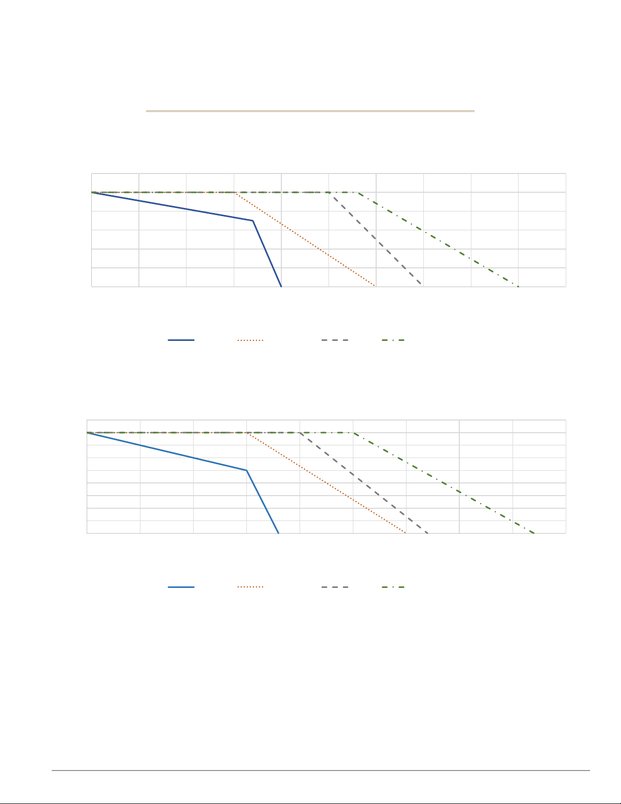
Pressure (PSIG)
BV2C Series Sanitary Ball Valve
Pressure –Temperature Charts
1/2" - 2"
1200
1000
800
600
400
200
0
0 50 100 150 200 250 300 350 400 450 500
Temperature (oF)
UHMW Virgin PTFE RTFE Carbon & SS
2 1/2" - 4"
900
800
700
600
500
400
300
Pressure (PSIG)
200
100
0
0 50 100 150 200 250 300 350 400 450
Temperature (oF)
UHMW Virgin PTFE RTFE Carbon & SS
7 dixonvalve.com • 800.789.1718 BV2C IOM

Non-Encapsulated
(in. lbs.)
Encapsulated
(in. lbs.)
(Cv)
½"
BV2C*-050CC-A
1.7
160
55
105
8
¾"
BV2C*-075CC-A
2.2
160
71
116
29
1"
BV2C*-100CC-A
3.1
160
101
336
66
1½"
BV2C*-150CC-A
6.2
200
221
420
192
2"
BV2C*-200CC-A
9.4
212
345
473
434
2 ½ " BV2C*-250CC-A
19.8
221
683
788
723
3"
BV2C*-300CC-A
26.0
239
830
1155
1124
4"
BV2C*-400CC-A
48.6
266
1323
1680
2100
Body Leakage
(atm-cc/sec)
1 ½”
2” – 4”
1 X 10
-9
1 X 10
10
-5
Torr
10
Torr
Code
Designation
Material
Applications
V
Virgin PTFE
Virgin
100% PTFE
Food Grade Material
G
RTFE
15% Glass reinforced
15% Glass filled + 85% PTFE
Food Grade Material
C
25% Carbon PTFE
25% Carbon
25% Carbon +75% PTFE
applications. Higher cycle life than RTFE.
Food Grade Material
U
UHMW
Ultra-high molecular
Specified for its low modulus of abrasion and
Food Grade Material
Technical Specifications
Size
* Refer to seat material codes below.
** Torque is measured at the valve stem with virgin PTFE seats, 100 PSI differential pressure, ambient temperature and fluid with a
specific gravity of 1.0. For varying conditions or other seat options, please contact Dixon Sanitary. When the valve is not factory actuated
by Dixon Sanitary, an additional safety factor is recommended.
Part #
Weight (lbs.)
Information supplied based on water media at 68°F
Assembly Torque
(in. lbs.)
Break Torque **
Break Torque **
Flow
Coefficient
Vacuum Testing (virgin PTFE seats)
Valve Size
Helium Leak Rate Test
½” –
Seat Materials
S
Stainless Steel PTFE
-7
polytetrafluoroethylene
tetrafluoroethylene
reinforced
tetrafluoroethylene
50% Stainless steel
filled
tetrafluoroethylene
weight polyethylene
-4
Our standard seat material. Ideal for most
sanitary services. Specified for applications
requiring a low co-efficient of friction.
Slightly higher temperature and pressure rating than
PTFE. Specified for applications requiring higher
cycle life than PTFE.
Specified for higher temperature pressure
applications. Ideal for steam and thermal fluid
50% Stainless steel + 50% PTFE Specified for
higher temperature pressure applications in a
sanitary process.
minimal property degradation when exposed to
moderate levels of radiation. I deal for
applications where fluorocarbons are not
acceptable.
8 dixonvalve.com • 800.789.1718 BV2C IOM
Installation & Start-Up
The following should be performed upon receiving the product and prior to installation and use of the product. It is important that all
the following processes and procedures are carefully followed and adhered to. Dixon
occurs during the unpacking or installation proc ess.
®
is not responsible for any damage that
Unpacking
Carefully unpack all the parts of the ball valve and inspect each part for any damage that may have occurred during shipment.
Report any damage to the carrier immediately. The ports on the valve are protected with a plastic cover. If any covers are missing or
damaged, inspect the ports on the valve thoroughly for any damage. Please add this manual to the plant maintenance file s for future
use and reference. Additional information for the valve can be found at dixonvalve.com.
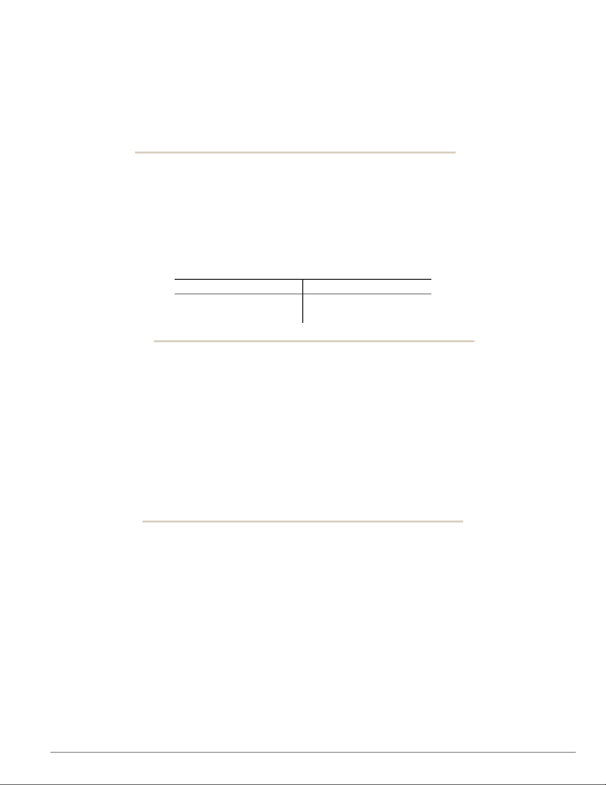
The product consists of the following components:
Item # Description
1 Valve
2 Handle
Tools Needed
The following tools will be required for any maintenance of the product:
• set of metric box wrenches
• Torque wrench
• Jax® PurGel Klear lubricating grease
• O-ring pick tool
• flathead screw driver
Welding
• For equipment delivered with weld end connections, any rubber or plastic components MUST be removed from the equipment
prior to welding. (See disassembly instructions for proper removal of such components.)
• Follow all necessary safety precautions, check lists and standard procedures prior to performing any welding on the equipment.
• Weld the equipment into the process line, being sure to follow and comply with appropriate industry welding procedures and
standards. For equipment used in food, beverage or dairy applications that carries 3A
section E1.1.1 for proper procedure and requirements.
• Re-assemble the equipment per the assembly section of this manual.
• Check the equipment for proper operation and perform leak test if necessary.
®
certification, see 3A® standard 00-01-2018
9 dixonvalve.com • 800.789.1718 BV2C IOM

Installation & Start-Up
Function Testing
• Check visually to ensure that the equipment is not leaking.
• Any defective seal that could have been damaged during disassembl y or assembly must be replaced.
• Check all equipment components for any signs of damage and replace damaged components.
• Ensure that all screw fittings are tight if applicable.
• Ensure that any pneumatic hose connections are free of leaks if applicable.
• Confirm all pipes and fittings connected to the equipment permitted for use are in the intended pressure range.
• Confirm all electrical installations are protected sufficiently and in accordance with appropriate safety standards if applicable.
• Check that the maximum pressure indicated on the equipment or in the specifications section of this manual has been complied
with.
Installation Orientation
Equipment must be installed in the proper orientation to ensure proper functionality and cleanability. Please refer to the following
instructions below for proper installation.
Valve Installation:
• Valves should not be installed between ferrules with damaged faces.
• Tubing should also be checked for proper alignment.
• Ball valves should never be used to align improperly positioned tube.
• The distance between ferrules should be checked to assure proper clearance of valve installation.
• For convenience in packaging and storage, some valv es are ship ped partially assembled including body ass emb ly and handle
assembly. (Refer to assembly and disassembly instructions.)
• The valve should be cycled to assure no binding or interference is taking place.
• Install adequate line supports to prevent str a in and stre ss on fittin gs, valves, and connections.
• Support straight runs of tubing at least every ten feet.
• Install supports on both sides of valves as close to the connection as possible.
• Install supports at each change of line direction.
• For lines penetrating walls or floors, allow a minimum of 1” clearance for expansion and contraction.
• Align valves and gaskets such that they are centered with the ferrules faces.
• Clamp ends must be parallel in all planes and on centerline.
• Failure to insure line ends are parallel and centered could prevent proper sealing. Improperly sealed valves will leak.
• Tighten all standard clamp connect ion s to 25 in-lbs and high pressure bolted clamp s to 20 ft-lbs.
• After placement in the line, test the operation of the valve.
Valve installation for other end connection types:
• Follow the same guidelines as described above.
• Do not attempt to butt-weld a valve into a line without first removing the valve body subassembly. Dissipate heat away from the
valve body when welding.
10 dixonvalve.com • 800.789.1718 BV2C IOM

General Maintenance
To ensure proper operation of your Dixon
damage, check all fitting c onnections and screw connections for any loosening of the connections during equipment operation.
Maintain adequate spare parts stock for all replacement components on the piece of equipment. Please refer to the repair kits section
of the manual for complete component part number s and kit part numb ers.
Recommended intervals for one shift operation would be 3 months. However, only the user/owner can determine the appropriate
service intervals as the length between service intervals is dependent on the following parameters:
• duration of use per day – number of cycles
• type of product
• product temperature
• product viscosity
• cleaning agent
• type of cleaning (CIP/SIP/COP)
Please use the following c hart below for proper grease type for varying component materials. DO NOT use mineral or animalproduct-based greases. Check all visible seals for any signs of damage and replace as necessary. For sliding surfaces, use Jax
PurGel Klear food grade grease. If a different grease is used other than what is specified in this manual, there is risk of damaging the
seals. Lubrication is only required when the equipm ent is bei ng rea ssemb led aft er servi cin g .
®
equipment, proper maintenance must be performed at regular intervals. To prevent
Servicing Intervals
Lubrication
Seal Material Grease Type
®
PTFE JAX® PurGel Klear
25% Carbon PTFE JAX® PurGel Klear
50% SS PTFE JAX® PurGel Klear
15% Glass PTFE
UHMW
JAX® PurGel Klear
Do not grease
11 dixonvalve.com • 800.789.1718 BV2C IOM
General Maintenance
Inspection
Inspection of the components listed below should be done during regular servicing intervals. Before removing the equipment from
the process line, please take care to do the following:
o Clean the process line completely to remove any product that may be harmful if contacting a person.
o Prior to loosening the ferrule clamp bolts (with valve in the open position):
To prevent personal injury:
o Depressurize the piping at the valve.
o Drain tubing run as much as possible.
o Cycle the valve to drain any trapped fluid from the body cavity. The valve should be left fully open or fully closed.
o Vent line to relieve any pressure.
o Close valve, then:
To prevent personal injury:
o Disconnect all air and electrical power from the actuator, solenoid valve, and switch box, (if applicable) and tag for reinstallation.
o Remove the actuator, solenoid valve, and switch box, if any.
o Loosen clamps to decompress valve gasket sea ls.
o Secure necessary lifting equipment to valve assembly if necessary
o Remove clamps and valve from between ferrule.
o Close any isolation valves on either side of the equipment being serviced.
o Once the equipment has been removed from the line, cap the lines that were connected to the piece of equipment being
serviced to prevent any foreign material from entering the line.
Components to be inspected:
• Item 1: Valve seats and seals
• Item 2: Valve ball
• Item 3: Valve end s
Any components that show signs of severe wear or damage should be replaced during the scheduled maintenance time for the
equipment. Please refer to the assembly and disassembly section of this manual for proper instructions on removing and replacing
any worn or damaged components. Replacement components and repair kits can be found in the BOM or repair kits section of this
manual.
Cleaning
IMPORTANT: Before operating the equipment during formal production, please follow the guidelines listed below to ensure that your
equipment is clean and ready for service.
• Ensure that the equipment is installed in a proper orientation to allow the equipment to be cleaned and drained properly.
Reference the installation and startup section of the manual for orientation guidelines.
• Flush the equipment with an appropriate cleaning agent to remove any residue that may be on the equipment from shipping.
IMPORTANT: DO NOT use cleaning agents that will attack stainless steel or the elastomers that were supplied with the valve. If
you are unsure what elastomer is used in the valve, reference the part number key in this manual to make the determination.
• Follow any MSDS instructions for proper use or handling of cleaning agents.
• Flush the equipment sufficiently to remove any soiling from the product contact components. Depending on the process, there
may be varying amounts of soiling. Cleaning times and cleaning agent concentrations will vary depending on the product being
processed. It is the responsibility of the operator to determine and adjust these cleaning specifications as necessary.
12 dixonvalve.com • 800.789.1718 BV2C IOM

• The equipment should not be allowed to sit with product present in it for extended periods of time. Equipment should be cleaned
immediately after processing is complete.
Manual Cleaning (COP)
1. Refer to the disassembly section of the manual and follow instructions to remove all product contact components.
2. Inspect the product contact components of the equipment for any signs of possible damage. Replace components as necessary.
(See the equipment BOM in this manual for replacement component part numbers.)
3. Clean all surfaces of the product contact components by manually brushing in a bath of cleaning solution (acid detergents or
simple alkaline soda type detergents).
4. After cleaning, rinse all components thoroughly with water.
5. Refer to the assembly section of the manual and follow instructions to properly reassemble the equipment.
13 dixonvalve.com • 800.789.1718 BV2C IOM

Assembly and Disassembly
To ensure quality operation of your Dixon® equipment, the equipment must be disassembled and assembled properly to prevent
equipment damage during operation. Please follow the instructions contained in this manual carefully and be sure to follow any safety
warnings contained herein. If any questions should arise during the assembly or disassembly process that are not addressed in this
manual, please feel free to contact Dixon
1. Before reassembling the valve, examine the parts and repair or replace damaged or worn parts. Dixon recommends using
new seats and seals at each assembly.
2. Insert the stem #5 (with O-ring #7) and PTFE thrust washer #6 into the body #1 and through the stem bore in the body.
3. Install PTFE stem packing rings #8 over the stem and into the body bore.
4. Install the gland ring #9 and two spring washers #10 such that the lower washer’s concave side is facing upward and the top
washer is opposite.
5. Lubricate the gland nut threads #13 with appropriate food grade anti-seize. Install and tighten the gland to compress the
packing. The gland should be tightened just until snu g.
6. Lubricate the stem threads with an anti-galling lubricant.
rd
7. Install the 3
stem such that the handle is parallel to the line when the valve is in the open position.
8. Install the handle nut #13.
9. Position the stem to close the valve. Insert the bal l #3 into the body. Slide the stem tang into the ball slot, being careful not to
nick or scratch the ball.
10. Rotate the stem until the ball is in the open position.
11. Install valve seats #4 into the body.
12. Place a new body seals #17 in the mating cavities in the body making sure the seats and seals remain in position.
13. For valves with Clamp end caps, insert the end caps #2 onto the body, taking care not to cut seals.
14. For valves with end caps welded into piping, with valve open, spring end caps outward and slide body between them.
Release spring force from end caps to allow end cap flanges to sit flush against the body . Take care not t o cut seal s.
15. Turn the stem and close the valve.
16. Install bolts #14 or #14A with washers. Install and hand-tighten nuts.
17. Wrench tighten nuts in sequence shown in Table 1 (Page 14), keeping gap between body and end caps even and until
assembly torque (Page 8) is reac hed.
18. Remove the handle and finish tightening the gland nut until break torque (Page 8) is reached. Measure stem breakaway
torque for several cycles to verify repeatability. (Over-tightening significantly raises stem torque.) Re-assemble handle.
19. If the valve has Clamp end caps, reinstall the valve into the piping using appropriate gaskets and clamps.
20. If practical, leak test the seats, gaskets, and packing.
21. Dixon Sanitary recommends replacement of any valve exposed to fire.
washer #10 over the stem (concave side is facing upward). Place the handle (#15 or #15 A, B and C) on the
Tightening procedure for end connections:
1. Hand-tighten fasteners.
2. Wrench-tighten each fastener in the sequence illustrated unti l lock washers begin to compress.
3. Continue tightening bolts 1/8 turn until recommended assembly torque value (see page 8) is achieved.
4. Confirm valve torque at stem.
®
– Sanitary Division at 800.789.1718.
Assembly
14 dixonvalve.com • 800.789.1718 BV2C IOM

For valves with clamp end connections:
1. Loosen and remove the clamps connecting the valve to the piping. Then, remove the valve and gaskets.
2. Loosen and remove the hex nuts and lock washers from the bolts #14 or #14A.
3. Pull the end caps free #2 from t he body .
For valves with welded end connec t ion s:
1. The valve can be disassembled with the body subassembly swung out from the end fittings or it can be
disassembled with the body subassembly completely removed from the end fittings.
2. To swing out the body subassembly from the end fittings:
i. Open the valve.
ii. Loosen the hex nuts.
iii. Remove the bolts, nuts, and lock washers between the body. Do not remove the bolt that goes through the ring
on the body.
iv. Spring the connecting piping 1/8" to remove the compression on the body from the end caps.
v. Swing the body out from the end fittings until the body completely clears the end caps. The body’s swing out
ring will rotate about the bolt.
vi. The sprung piping can now be returned to its original compression, if desired.
3. To remove the entire body subassembly from the piping, in step iii above, remove all bolts.
Continued steps for all valve end connections:
4. Remove the body seals #17 and encapsulated ball seat #4.
5. Turn the stem to close the ball. Then, slide the ball #3 out of the body #1, taking care not to nick or scratch the ball.
6. Loosen and remove the handle nut #13 from the stem. Remove the handle, lock plate, and was her #10.
7. Unscrew and remove the gland nut #13 and two spring washers #10.
8. Push the stem into the body and out an open end of the body. Remove stem O-ring #7 and thrust washer #6.
9. Remove the gland ring #9 and PTFE stem packing rings #8.
10. Remove the stopper #16 from the body.
Disassembly
15 dixonvalve.com • 800.789.1718 BV2C IOM

Repair Kits
Valve
Size
Repair Kit
Part #
½"
BV-2"C or N"-*K050
¾"
BV-2"C or N"-*K075
1"
BV-2"C or N"-*K100
1½"
BV-2"C or N"-*K150
2"
BV-2"C or N"-*K200
2½ "
BV-2"C or N"-*K250
3"
BV-2"C or N"-*K300
4"
BV-2"C or N"-*K400
Code *
Description
V
U
virgin PTFE
. PTFE
UHMW
To ensure proper operation of your Dixon® equipment, proper maintenance must be performed at regular intervals. To prevent damage
and improper operation, use only genuine replacement parts and kits offered by Dixon
sure the parts are properly matched to the series , model, serial number and revision level of the equipment. Please see the list of kits
below offered for this piece of equipment:
®
to maintain the integrity of the equipment. Make
Repair Kit contains:
#4 (2) seats (encapsulated)
or
#4A (2) seats (non-encapsulated)
#6 (1) thrust washer
#7 (1) O-ring
#8 (3) stem packings
#17 (2) body seals
G
C
25% carbon PTFE
S
stainless rein
RTFE
16 dixonvalve.com • 800.789.1718 BV2C IOM

Bill of Materials
Quantity
½" to 2"
2½"
3"
4"
1
body
CFSM
1 1 1
1
2
end (4-bolt)
CFSM
2 2 2
n/a
2A
end (6-bolt)
CFSM
n/a
n/a
n/a
2
3
ball
CFSM
1 1 1
1
4
seat (encapsulated)
V, G, C, S or U
2 2 2
2
4A
seat (non-encapsulated)
V, G, C, S or U
2 2 2
2
5
stem
316
1 1 1
1
6
thrust washer
V, G, C, S or U
1 1 1
1
7
O-ring
FKM
1 1 1
1
8
stem packing
V, G, C, S or U
3 3 3
3
9
gland ring
316
1 1 1
1
10
bevel washer
301
3 3 3
3
11
hex nut
304
4 4 8
12
12
bolt washer
304
4 4 8
12
13
nut
304
2 2 2
2
14
bolt
304
4
n/a
n/a
n/a
14A
bolt (double thread)
304
n/a
4 4 6
15
handle
304/Vinyl
1
n/a
n/a
n/a
15A
handle (rod)
304/Vinyl
n/a 1 1
1
15B
handle head
304
n/a 1 1
1
15C
handle nut
304
n/a 1 1
1
16
stop pin
316
1 1 1
1
17
body seal
V, G, C, S or U
2 2 2
2
Item
Description
Material
17 dixonvalve.com • 800.789.1718 BV2C IOM

Dimensions
Size A B C D E F
G
H (mm)
½”
4.3
4.9
1.5
2.
3.1
F03
F04
9
¾”
4.7
4.9
1.8
2.2
3.4
F03
F04
9
1”
4.9
5.4
2.1
2.4
3.6
F04
F05
11
1 ½”
5.6
9.3
2.7
3.2
4.4
F05
F07
14
2”
6.4
9.3
3.1
3.8
4.7
F05
F07
14
2 ½”
7.8
18.0
3.8
4.9
5.2
F07
F10
17
3”
9.0
18.3
4.2
5.4
5.7
F07
F10
17
4”
9.6
18.3
5.3
8.7
6.9
F10
F12
22
.
All dimensions are in inches, unless noted. Dimensions are approximate.
Engineering dimensions are available upon request. Specifications are subject to change without notice.
18 dixonvalve.com • 800.789.1718 BV2C IOM

Part Number Key
Valve (1-4)
Seat Material (5)
(6)
Size (7-9)
End (10-11)
(12)
Actuation (13-15)
BV2C
Encapsulated
V
Virgin PTFE
-
050 1/2"
C
Clamp
-
Manual
G
RTFE
075
3/4"
B
Weld
C
25% Carbon PTFE
100
1" F Female 1-Line
All others (13-15)
S
50% SS PTFE
150
1-1/2"
M
Male 1-Line
U
UHMW
200
2" T Threaded Bevel
250
2-1/2"
P
Plain Bevel
300
3" Q Q-Line
400
4" J John Perry Plain
H
John Perry Threaded
E
Extended Weld
1
Female NPT
2
Male NPT
3
Socket Weld
To ensure proper specific ation of your Dixon
valve with the options that meet your specific requirements. If you require an option that is not listed in this key, please feel free to
contact Dixon® – Sanitary Division at 800.789.1718.
®
BV2C Series valve, below is the complete valve part number key to configure the
A - Standard
Contact Dixon Sanitary
19 dixonvalve.com • 800.789.1718 BV2C IOM

Troubleshooting
Process pressure / Temperature
Check process pressure and temperature to ensure it is below
limits.
pressure / temperature
For all other issues, please contact Dixon Sanitary – 800.789.1718
Problem
Valve will not open/close
Valve is leaking
Possible Cause
Obstructions in process line Remove valve and clear line.
Seat is damaged Replace seats and seals.
exceeds seat limits
Stem torque is too high.
Process
exceeds seat limits
Seats are damaged
Remove the valve if process exceeds all seat ratings.
Check stem torque and adjust gland nut.
Remove the valve if process exceeds all seat ratings.
Suggested Action
Change seat to proper material.
Change seat to proper material.
Replace seats
Replace stem packing.
20 dixonvalve.com • 800.789.1718 BV2C IOM

Limited Warranty
DIXON VALVE AND COUPLING COMPANY (herein called "Dixon") warrants the products described herein and manufactured by
Dixon to be free from defects in material and workmanship for a period of one (1) year from date of shipment by Dixon under normal
use and service. Its sole obligation under this warranty being limited to repairing or replacing, as hereinafter provided, at its option
any product found to Dixon's satisfaction to be defective upon examination by it, provided that such product shall be returned for
inspection to Dixon's factory within three (3) months after discovery of the defect. The repair or replacement of defective products
will be made without charge for parts or labor. This warranty shall not apply to: (a) parts or produ cts not man ufa cture d by D ixon,
the warranty of such items being limited to the actual warranty extended to Dixon by its supplier; (b) any product that has been
subject to abuse, negligence, accident, or misapplication; (c) any product altered or repaired by others than Dixon; and (d) to normal
maintenance services and the replacement of service items (such as washers, gaskets and lubricants) made in connection with
such services. To the extent permitted by law, this limited warranty shall extend only to the buyer and any other person reasonably
expected to use or consume the goods who is injured in person by any breach of the warranty. No action may be brought against
Dixon for an alleged breach of warranty unless such action is instituted within one (1) year from the date the cause of action accrues.
This limited warranty shall be construed and enforced to the fullest extent allowable by applicable law.
Other than the obligation of Dixon set forth herein, Dixon disclaims all warranties, express or implied, including but not limited to any
implied warranties of merchantability or fitness for a particular purpos e, and any other obligation or liability. The foregoing constitutes
Dixon's sole obligation with respect to damages, whether direct, incidental or consequential, resulting from the use or performance of
the product.
Some products and sizes may be discontinued when s tock is depleted or may require a minimum quantity for ordering
dixonvalve.com • 800.789.1718 BV2C IOM
21

Dixon, founded in 1916, is a premier manufacturer and supplier
of hose couplings, valves, dry-disconn ect s, sw iv els, and other
fluid transfer and control products. The co mpa ny ’s glob al rea ch
includes a wide range of products for numerous industries
including petroleum exploration, refining, transportation, chemical
processing, food & beverage, steel, fire protection, construction,
mining and manufacturing. Dixon’s strategic objective is to
create solutions that make products safer, leak -free, longer
lasting, and always available.
Dixon Sanitary
N25 W23040 Paul Road • Pewaukee, WI 53072
Customer Service: 800.789.1718
sanitarysales@dixonvalve.com
Fax: 800.789.4046
dixonvalve.com
© 2019 DVCC Printed in the USA DS_IOmanual_BV2C 03/2019
 Loading...