

Page 1
Instructions and Operations Manual
for
Inline, Side Entry, Side Outlet
& Dual Strainers
Read and understand this manual prior to installing, operating or servicing this equipment.
Dixon Sanitary
N25 W23040 Paul Road • Pewaukee, WI 53072
ph: 800.789.1718 • fx: 800.789.4046
dixonvalve.com
February 2019
Page 2

Table of Contents
Safety ................................................................................................................................................................................................... 3
Care of Stainless Steel ......................................................................................................................................................................... 4
Technical Specications .................................................................................................................................................................... 5-6
Installation and Start-Up ....................................................................................................................................................................... 7
General Maintenance ........................................................................................................................................................................... 8
Changing Filter Media ..................................................................................................................................................................... 9-15
Inline ............................................................................................................................................................................................ 10-11
Disassembly .................................................................................................................................................................................. 10
Assembly....................................................................................................................................................................................... 10
BOM .............................................................................................................................................................................................. 11
Side Entry ...................................................................................................................................................................................... 12-13
Disassembly .................................................................................................................................................................................. 12
Assembly....................................................................................................................................................................................... 12
BOM .............................................................................................................................................................................................. 13
Side Outlet ..................................................................................................................................................................................... 14-15
Disassembly .................................................................................................................................................................................. 14
Assembly....................................................................................................................................................................................... 14
BOM .............................................................................................................................................................................................. 15
Dimensions ......................................................................................................................................................................................... 16
Inline.............................................................................................................................................................................................. 16
Side Entry & Side Outlet .............................................................................................................................................................. 16
Warranty ............................................................................................................................................................................................. 17
2 Strainer I & O Manual 800.789.1718
Page 3

Safety Information
Do’s and Don’ts
• Do read and understand these instructions before installing or using the strainer.
• Do use Dixon spare parts when replacing any components of the strainer.
• Do Not attempt to service the strainer while under pressure.
• Do Not place the strainer in an application where the service ratings are exceeded.
• Do Not attempt to modify the strainer assembly as it may compromise the integrity of the assembly and will void all warranties.
Safety Precautions When Installing Strainer
• Do relieve product line pressure before attempting to install strainer assembly.
• Do check the distance between the clamp ferrules to assure there is proper clearance for the strainer assembly.
• Do Not install a damaged lter or strainer.
• Do Not install strainer between damaged clamp ferrules.
• Do Not install strainer between tubing that is signicantly out of alignment.
Safety Precautions When Strainer is in Operation
• Do monitor the strainer assembly for any signs of leaks.
• Do check all clamp assemblies often to ensure that they have not loosened from any excessive vibration.
• Do check the pressure on either side of the strainer to monitor for any possible blockages.
• Do Not attempt to loosen any clamp assemblies while the strainer is in operation.
• Do Not attempt to perform any type of service or adjustment to the strainer during operation.
Safety Precautions When Servicing the Strainer
• Do drain piping run as much as possible.
• Do vent line to relieve any pressure.
• Do secure necessary lifting equipment to strainer assembly if necessary.
• Do remove line clamps rst before removing strainer body clamp.
• Do use caution and wear protective clothing if strainer has been used in applications using acids or other chemicals that may be
harmful.
3Strainer I & O Manual 800.789.1718
Page 4

Care of Stainless Steel
The stainless steel components in Dixon Sanitary equipment are machined, welded and assembled by skilled craftsmen using
manufacturing methods that preserve the corrosion-resistant quality of the stainless steel.
Retention of corrosion-resistant qualities under processing conditions requires regular attention to the precautions listed below.
1. Regularly check all electrical devices connected to the equipment for stray currents caused by improper grounding, damaged
insulation or other defects. Corrosion: Pitting often occurs when stray currents come in contact with moist stainless steel.
2. Never leave rubber mats, ttings, wrenches, etc. in contact with stainless steel. Corrosion: Pitting or galvanic action. Objects
retard complete drying, preventing air from reforming the protective oxide lm. Galvanic corrosion occurs when two dissimilar
metals touch when wet.
3. Immediately rinse equipment after use with warm water until the rinse water is clear. Clean the equipment (manual or CIP)
as soon as possible after rinsing. Corrosion: discoloration, deposits, pitting. Product deposits often cause pitting beneath the
particles.
4. Use only recommended cleaning compounds. Purchase chemicals from reputable and responsible chemical manufacturers
familiar with stainless steel processing equipment, they continuously check the effects of their products on stainless steel.
5. Use cleaning chemicals exactly as specied by the manufacturer. Do not use excessive concentrations, temperatures or exposure
times. Corrosion: Pitting, discoloration, stress cracks. Permanent damage often occurs from excessive chemical concentrations,
temperatures or exposure times.
6. For manual cleaning, use only soft non-metallic brushes, sponges or pads. Brush with the grain on polished surfaces, avoid
scratching the surface. Corrosion: Pitting, scratches. Metal brushes or sponges will scratch the surface and promote corrosion
over a period of time. Metal particles allowed to remain on a stainless steel surface will cause pitting.
7. Use chemical bactericides exactly as prescribed by the chemical manufacturer in concurrence with local health authority. Use
the lowest permissible concentration, temperature and exposure time possible. Flush immediately after bacterial treatment. In no
case should the solution be in contact with stainless steel more then 20 minutes. Corrosion: Protective lm destroyed. Chlorine
and other halogen bactericides can destroy the protective lm. A few degrees increase in temperature greatly increases chemical
activity and accelerates corrosion.
8. Regularly inspect the joints in pipelines. Be sure all connections are tight tting without binding. Corrosion: Crevice corrosion.
Small crevices caused by improperly seated gaskets will promote crevice corrosion. Stainless steel under stress will develop
stress cracking especially in the presence of bactericides containing chlorine.
9. Regularly inspect equipment for surface corrosion (i.e. pitting deposits, stress cracks, etc.). If deposit or color corrosion is
detected, remove it immediately using mild scouring powder and detergents. Rinse thoroughly and allow to air dry. Review
production and cleaning procedures to determine the cause. Note: If corrosion is not removed, the protective lm cannot be
restored and corrosion will continue at an accelerated rate.
4 Strainer I & O Manual 800.789.1718
Page 5

Specications:
Technical Specications
Model Maximum Pressure (PSI)
BSCCQ1
BSCCQ2
BSCCQ3
BSCCQ4
BSCCS1
BSCCS2
290 PSI at 70°F
175 PSI at 210°F
Maximum Differential
Single Strainer - 50 PSI
Materials:
• Product wetted steel parts: AISI 316L Stainless Steel
• Product wetted elastomers: Buna (Standard)
• Optional wetted elastomers: FKM
• Non-Wetted components: CF8
• Finish: 32 Ra on product contact surfaces
Strainer Back Up Tubes:
• Full ow coarse strainer tubes
• 1/4" perforations standard
• 1/8” perforations available
Filters:
• Full ow lters
• Micron rating from 40 to 800 (others available upon request)
• Polyester, Cotton cheesecloth, and Nylon mesh lter material available
Pressure (PSI)
Overscreen - 25 PSI
Filter - 10 PSI
Maximum Temperature
250°F
Mesh Over Screens:
• Full ow ne and medium over screens (not 3A compliant)
• Square mesh 20 to 100
Connections:
• Clamp (Standard)
• Bevel Seat, I-Line, and Weld ends available
Sizes:
• 1" to 3"
Types:
• Inline
• Short
• Long
• Side Entry
• Long
• Side Outlet
• Long
5Strainer I & O Manual 800.789.1718
Page 6
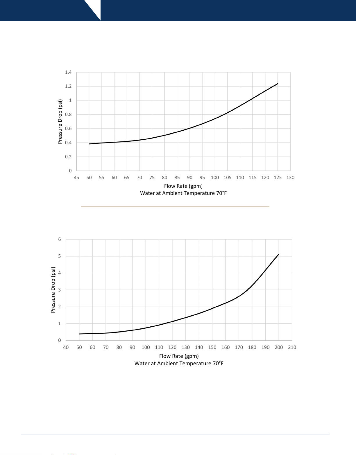
Technical Specications
Pressure Drop Chart - Short Strainers
Pressure Drop Chart - Long Strainers
6 Strainer I & O Manual 800.789.1718
Page 7

Installation & Start Up
Inline, Side Entry and Side Outlet
1. Be sure adequate line supports exist to prevent stress on ttings and strainer body.
2. Install supports approximately every ten feet on either side of the strainer assembly.
3. All Dixon strainer assemblies operate in any position. However, to maintain 3A certication, the unit must be installed in the
vertical position.
4. Ensure that the strainer assembly is in the proper orientation so that the inlet and outlet are congured according to the markings
on the strainer body.
5. Align the lter, strainer and gaskets such that they are centered with the clamp ferrule faces.
6. Clamp ends must be parallel in all planes and on center line. CAUTION: Failure to ensure line ends are centered and parallel in
all planes, could result in leaking from the valve or strainer assembly.
7. Tighten all standard clamp assemblies to 25 in-lbs and high pressure bolted clamps to 20 ft-lbs.
8. Once strainer assembly is installed, cycle water through the unit to ensure there are no leaks from any of the connection points.
Dual Strainers
1. When installing a dual strainer assembly with ball or buttery valves, install supports on both sides of the valves as close to the
connections as possible.
2. Before starting product ow through the dual strainer unit, ensure that the valves are in the correct position. On manual ball
valves, check the ow path machined in the valve stem to ensure that the valves are positioned so that product is only owing
through a single strainer at any one time. For actuated valves, check the indicator beacon located on top of the actuator.
3. For proper ow direction and orientation, please refer to the following diagram.
Inlet
Pos. 1 Pos. 2
Flow Direction
Outlet
Outlet
4. Install supports approximately every ten feet on either side of the strainer assembly.
5. All Dixon strainer assemblies operate in any position. However, to maintain 3A certication, the unit must be installed in the
vertical position.
6. Ensure that the strainer assembly is in the proper orientation so that the inlet and outlet are congured according to the markings
on the strainer body.
7. Align the lter, strainer and gaskets such that they are centered with the clamp ferrule faces.
8. Clamp ends must be parallel in all planes and on center line. CAUTION: Failure to ensure line ends are centered and parallel in
all planes, could result in leaking from the valve or strainer assembly.
9. Tighten all standard clamp assemblies to 25 in-lbs and high pressure bolted clamps to 20 ft-lbs.
10. Once strainer assembly is installed, cycle water through the unit to ensure there are no leaks from any of the connection points.
Flow Direction
7Strainer I & O Manual 800.789.1718
Page 8

General Maintenance
1. WARNING: Prior to loosening the ferrule clamps, be sure to drain piping as much as possible to prevent injury.
2. Vent line to relieve any pressure that could potentially be built up in the strainer housing.
3. Loosen clamps to decompress valve gasket seals.
4. Secure any necessary lifting equipment required to remove the strainer from the line.
5. Completely remove clamps from the strainer ends and remove the unit from between the clamp ferrules.
6. Check all wetted components for any sign of damage that could have resulted from large particulate or water hammer.
7. For dual strainer units, inspect valves for any signs of damage and replace wetted components as necessary. Refer to Dixon ball
and buttery manuals for instructions.
8. Remove and replace as necessary the lter bag or mesh over screen.
9. The strainer back up tube should not need to be replaced unless signicant damage has occurred as a result of abnormally harsh
media.
8 Strainer I & O Manual 800.789.1718
Page 9

Changing Filter Media
1. When installing a lter sock or over screen, save the original packaging. This will aid in identifying your lter media type when
reordering.
2. Relieve all pressure inside the system and make certain the ltration system is drained of all liquid.
3. Refer to the disassembly section of the manual for procedures on removing the back-up tube and lter bag or over screen
assembly.
4. If you are using a lter bag (8), remove retaining rings (9) from either end of the strainer back-up tube (4). Check the retaining rings
for any sign of wear or damage, and replace as necessary.
5. If you are using an over screen (7), slide the over screen off of the strainer back-up tube (4) and clean or replace as necessary.
6. Insert a new lter bag (8) or over screen (7) over the strainer back-up tube (4). If using a lter bag, insert the retainer rings (9)
inside each end of the strainer back-up tube to hold the lter bag in place.
7. Refer to the Assembly section of the manual for reassembly of the strainer unit.
9Strainer I & O Manual 800.789.1718
Page 10

Inline
Disassembly
1. Remove the clamp (10) and lift off the outlet assembly (1). Note: Apply pressure to the outlet assembly when you remove the
clamp, as the spring (2) will force the outlet assembly away from the body (6) when the clamp is removed.
2. Remove the gasket (3) and inspect it for damage or wear.
3. Remove the spring (2) and the distributor cap (5).
4. Remove the back-up tube (4) and the lter bag (8) or mesh over screen (7).
5. Change the mesh over screen (7) or lter bag (8) if necessary. Refer to Changing The Filter Media section of the manual for
specic instructions.
Assembly
1. Ensure that the lter media is in place on the strainer back-up tube (4). Refer to the Changing The Filter Media section of the
manual for specic instructions.
2. Place the gasket (3) on the outlet assembly (1).
3. Place the strainer back up tube (4) in the outlet assembly (1).
4. Press the distributor cap (5) onto the strainer back-up tube (4).
5. Press the spring (2) onto the outside diameter of the distributor ca p.
6. Press the strainer inlet (6) over the entire assembly and compress it to the outlet assembly (1).
7. Attach and tighten the squeeze clamp (10) to 25 in-lbs.
10 Strainer I & O Manual 800.789.1718
Page 11

Inline
Bill of Materials
Item # Description 1" Part # 1½" Part # 2" Part # 2½" Part # 3" Part # Material Qty
Strainer End Cap (Short) BS-01-R100 BS-01-R150 BS-01-R200 BS-01-R250 BS-01-R300 316L 1
1
Strainer End Cap (Long) -- BS-01-R151 BS-01-R201 -- BS-01-R301 1
2 Strainer Spring BS-02-R100-200 BS-02-R250-300 BS-02-R250-300 1
3 Gasket 40MP-U400 40MPV-U400 40MPV-U400 Buna 1
Back-Up Tube ⅛" Perforations (Short) BS-1418-R100200 BS-1418-R250300 BS-1418-R250300 316L 1
Back-Up Tube ⅛" Perforations (Long) BS-2418-R100200 BS-2418-R250300 BS-2418-R250300 1
4
Back-Up Tube ¼" Perforations (Short) BS1425-R100200 BS-1425-R250300 BS-1425-R250300 1
Back-Up Tube ¼" Perforations (Long) BS-2425-R100200 BS-2425-R250300 BS-2425-R250300 1
5 Distributor Cap BS-05-R100-200 BS-05-R250-300 BS-05-R250-300 1
Strainer Inlet (Short) BS-16-R100 BS-16-R150 BS-16-R200 BS-16-R250 BS-16-R300 1
6
Strainer Inlet (Long) -- BS-26-R150 BS-26-R200 -- BS-26-R300 1
7 Mesh Over Screen (Short/Long) Contact Dixon Sanitary For Options -- 1
8 Filter Bag (Short/Long) Contact Dixon Sanitary For Options -- 1
9 Retaining Ring BS-09-U100-200 BS-09-U250-300 Buna 2
10
Squeeze Clamp 13MHHM-Q400 13MHHMV-Q400 CF8 1
11Strainer I & O Manual 800.789.1718
Page 12

Side Entry
Disassembly
1. Remove the clamp (10) and lift off the end cap with handle (1).
2. Remove the gasket (3) and inspect it for damage or wear.
3. Remove the spring (2) and the distributor cap (5).
4. Remove the back-up tube (4) the lter bag (8) or the mesh over screen (7).
5. Change the mesh over screen (7) or lter bag (8) if necessary. Refer to Changing The Filter Media section of the manual for
specic instructions.
Assembly
1. Ensure that the lter media is in place on the strainer back-up tube (4). Refer to the Changing The Filter Media section of the
manual for specic instructions.
2. Insert the strainer back-up tube (4) inside the strainer body (6) ensuring that the bottom of the back-up tube is seated rmly against
the bottom of the strainer body.
3. Insert the distributor cap (5) inside the strainer body (6) ensuring that the cap is seated rmly against the top of the strainer back-
up tube (4). Note: The opening on the handle of the distributor cap should be facing the opening of the inlet port so that the port is
not blocked.
4. Insert the spring (2) inside the strainer body (6) ensuring that the spring is seated rmly against the ridge on the distributor cap (5).
5. Place the gasket (3) on the strainer body (6).
6. Compress the end cap with handle (1) onto the strainer body (6) and attach and tighten the squeeze clamp (10) to 25 in-lbs.
12 Strainer I & O Manual 800.789.1718
Page 13

Side Entry
Bill of Materials
Item # Description 1½" Part # 2" Part # 3" Part # Material Qty
1 End Cap With Handle BS-31-R100-200 BS-31-R250-300
2 Strainer Spring BS-32-R100-200 BS-32-R250-300 1
3 Gasket 40MP-U400 40MPV-U400 Buna 1
4 Back-Up Tube ⅛" Perforations BS-2418-R100200 BS-2418-R250300
Back-Up Tube ¼" Perforations BS-2425-R100200 BS-2425-R250300 1
5 Distributor Cap BS-35-R100-200 BS-35-R250-300 1
6 Strainer Body BS-36-R150 BS-36-R200 BS-36-R300 1
7 Mesh Over Screen Contact Dixon Sanitary For Options -- 1
8 Filter Bag Contact Dixon Sanitary For Options -- 1
9 Retaining Ring BS-09-U100-200 BS-09-U250-300 Buna 2
10
Squeeze Clamp 13MHHM-Q400 13MHHV-Q400 CF8 1
316L
316L
1
1
13Strainer I & O Manual 800.789.1718
Page 14

Side Outlet
Disassembly
1. Remove the clamp (10) and lift off the end cap with handle (1).
2. Remove the gasket (3) and inspect it for damage or wear.
3. Remove the stand-off tube (11) and the PTFE retainer ring (12).
4. Remove the back-up tube (4) and the lter bag (8) or mesh over screen (7).
5. Change the mesh over screen (7) or lter bag (8) if necessary. Refer to Changing The Filter Media section of the manual for
specic instructions.
Assembly
1. Ensure that the lter media is in place on the strainer back-up tube (4). Refer to the Changing The Filter Media section of the
manual for specic instructions.
2. Place the distributor cap (5) on the strainer back-up tube (4) ensuring that the cap is seated rmly against the back-up tube.
3. Place the spring (2) on the distributor cap (5) making sure that the spring is seated rmly on the ridge of the cap.
4. Insert the back-up tube (4), distributor cap (5), and spring (2) assembly into the strainer body (6).
5. Press the PTFE retainer ring (12) rmly into place on top of the back-up tube assembly.
6. Place the stand-off tube (11) inside the strainer body (6) with the three legs facing toward the retainer ring (12).
7. Place the gasket (3) on the strainer body (6).
8. Compress the end cap with handle (1) onto the strainer body and attach and tighten the squeeze clamp (10) to 25 in-lbs.
14 Strainer I & O Manual 800.789.1718
Page 15

Side Outlet
Bill of Materials
Item # Description 1½" Part # 2" Part # 3" Part # Material Qty
1
2
3
4
5
6
7
8
9
10
11
12
End Cap With Handle BS-31-R100-200 BS-31-R250-300
Strainer Spring BS-02-R100-200 BS-02-R250-300 1
Gasket 40MP-U400 40MPV-U400 Buna 1
Back-Up Tube ⅛" Perforations BS-1418-R100200 BS-2418-R250300
Back-Up Tube ¼" Perforations BS-1425-R100200 BS-2425-R250300 1
Distributor Cap BS-05-R100-200 BS-05-R250-300 1
Strainer Body BS-36-R150 BS-36-R200 BS-36-R300 1
Mesh Over Screen Contact Dixon Sanitary For Options -- 1
Filter Bag Contact Dixon Sanitary For Options -- 1
Retaining Ring BS-09-U100-200 BS-09-U250-300 Buna 2
Squeeze Clamp 13MHHM-Q400 13MHHV-Q400 CF8 1
Stand-Off Tube BS-411-R100-200 BS-411-R250-300 316L 1
Retainer Ring BS-412-R100-200 BS-412-R250-300 PTFE 1
316L
316L
1
1
15Strainer I & O Manual 800.789.1718
Page 16

Dimensions
Short and Long Inline
Size
1"
1½" 15.75 35.38 4.00 5.10
2" 15.75 35.38 4.00 5.10
2½" 15.75 -- 4.50 5.70
3" 15.75 35.38 4.50 5.70
A
Short
15.75 -- 4.00 5.10
A
Long
B C
Side Entry and Side Outlet
Size A B C D
1½"
2" 41.90 4.00 35.00 3.50
3" 41.90 4.50 35.00 3.75
16 Strainer I & O Manual 800.789.1718
41.90 4.00 35.00 3.50
Page 17

Limited Warranty
DIXON VALVE AND COUPLING COMPANY (herein called "Dixon") warrants the products described herein, and manufactured by
Dixon to be free from defects in material and workmanship for a period of one (1) year from date of shipment by Dixon under normal
use and service. It's sole obligation under this warranty being limited to repairing or replacing, as hereinafter provided, at its option
any product found to Dixon's satisfaction to be defective upon examination by it, provided that such product shall be returned for
inspection to Dixon's factory within three (3) months after discovery of the defect. The repair or replacement of defective products
will be made without charge for parts or labor. This warranty shall not apply to: (a) parts or products not manufactured by Dixon,
the warranty of such items being limited to the actual warranty extended to Dixon by its supplier; (b) any product that has been
subject to abuse, negligence, accident, or misapplication; (c) any product altered or repaired by others than Dixon; and (d) to normal
maintenance services and the replacement of service items (such as washers, gaskets and lubricants) made in connection with
such services. To the extent permitted by law, this limited warranty shall extend only to the buyer and any other person reasonably
expected to use or consume the goods who is injured in person by any breach of the warranty. No action may be brought against
Dixon for an alleged breach of warranty unless such action is instituted within one (1) year from the date the cause of action accrues.
This limited warranty shall be construed and enforced to the fullest extent allowable by applicable law.
Other than the obligation of Dixon set forth herein, Dixon disclaims all warranties, express or implied, including but not limited to any
implied warranties of merchantability or tness for a particular purpose, and any other obligation or liability. The foregoing constitutes
Dixon's sole obligation with respect to damages, whether direct, incidental or consequential, resulting from the use or performance of
the product.
Some products and sizes may be discontinued when stock is depleted, or may require a minimum quantity for ordering.
17Strainer I & O Manual 800.789.1718
Page 18

Dixon™, founded in 1916, is a premier manufacturer and
supplier of hose couplings, valves, dry-disconnects, swivels,
and other fluid transfer and control products. The company’s
global reach includes a wide range of products for numerous
industries including petroleum exploration, refining,
transportation, chemical processing, food & beverage, steel,
fire protection, construction, mining and manufacturing.
Dixon™’s strategic objective is to create solutions that make
products safer, leak-free, longer lasting, and always available.
dixonvalve.com • Customer Service: 800.789.1718
Dixon Sanitary
N25 W23040 Paul Road • Pewaukee, WI 53072
Customer Service: 800.789.1718
Fax: 800.789.4046
Dixon
Customer Service
© 2015 DVCC Strainer I & O Manual_inhouse1015
 Loading...