

Dixon BSCCQ1, BSCCQ2, BSCCS2, BSCCQ3, BSCCQ4 Instruction And Operation Manual
...
Instructions and Operations Manual
for
Inline, Side Entry, Side Outlet
& Dual Strainers
Read and understand this manual prior to installing, operating or servicing this equipment.
Dixon Sanitary
N25 W23040 Paul Road • Pewaukee, WI 53072
ph: 800.789.1718 • fx: 800.789.4046
dixonvalve.com
February 2019

Table of Contents
Safety ................................................................................................................................................................................................... 3
Care of Stainless Steel ......................................................................................................................................................................... 4
Technical Specications .................................................................................................................................................................... 5-6
Installation and Start-Up ....................................................................................................................................................................... 7
General Maintenance ........................................................................................................................................................................... 8
Changing Filter Media ..................................................................................................................................................................... 9-15
Inline ............................................................................................................................................................................................ 10-11
Disassembly .................................................................................................................................................................................. 10
Assembly....................................................................................................................................................................................... 10
BOM .............................................................................................................................................................................................. 11
Side Entry ...................................................................................................................................................................................... 12-13
Disassembly .................................................................................................................................................................................. 12
Assembly....................................................................................................................................................................................... 12
BOM .............................................................................................................................................................................................. 13
Side Outlet ..................................................................................................................................................................................... 14-15
Disassembly .................................................................................................................................................................................. 14
Assembly....................................................................................................................................................................................... 14
BOM .............................................................................................................................................................................................. 15
Dimensions ......................................................................................................................................................................................... 16
Inline.............................................................................................................................................................................................. 16
Side Entry & Side Outlet .............................................................................................................................................................. 16
Warranty ............................................................................................................................................................................................. 17
2 Strainer I & O Manual 800.789.1718

Safety Information
Do’s and Don’ts
• Do read and understand these instructions before installing or using the strainer.
• Do use Dixon spare parts when replacing any components of the strainer.
• Do Not attempt to service the strainer while under pressure.
• Do Not place the strainer in an application where the service ratings are exceeded.
• Do Not attempt to modify the strainer assembly as it may compromise the integrity of the assembly and will void all warranties.
Safety Precautions When Installing Strainer
• Do relieve product line pressure before attempting to install strainer assembly.
• Do check the distance between the clamp ferrules to assure there is proper clearance for the strainer assembly.
• Do Not install a damaged lter or strainer.
• Do Not install strainer between damaged clamp ferrules.
• Do Not install strainer between tubing that is signicantly out of alignment.
Safety Precautions When Strainer is in Operation
• Do monitor the strainer assembly for any signs of leaks.
• Do check all clamp assemblies often to ensure that they have not loosened from any excessive vibration.
• Do check the pressure on either side of the strainer to monitor for any possible blockages.
• Do Not attempt to loosen any clamp assemblies while the strainer is in operation.
• Do Not attempt to perform any type of service or adjustment to the strainer during operation.
Safety Precautions When Servicing the Strainer
• Do drain piping run as much as possible.
• Do vent line to relieve any pressure.
• Do secure necessary lifting equipment to strainer assembly if necessary.
• Do remove line clamps rst before removing strainer body clamp.
• Do use caution and wear protective clothing if strainer has been used in applications using acids or other chemicals that may be
harmful.
3Strainer I & O Manual 800.789.1718

Care of Stainless Steel
The stainless steel components in Dixon Sanitary equipment are machined, welded and assembled by skilled craftsmen using
manufacturing methods that preserve the corrosion-resistant quality of the stainless steel.
Retention of corrosion-resistant qualities under processing conditions requires regular attention to the precautions listed below.
1. Regularly check all electrical devices connected to the equipment for stray currents caused by improper grounding, damaged
insulation or other defects. Corrosion: Pitting often occurs when stray currents come in contact with moist stainless steel.
2. Never leave rubber mats, ttings, wrenches, etc. in contact with stainless steel. Corrosion: Pitting or galvanic action. Objects
retard complete drying, preventing air from reforming the protective oxide lm. Galvanic corrosion occurs when two dissimilar
metals touch when wet.
3. Immediately rinse equipment after use with warm water until the rinse water is clear. Clean the equipment (manual or CIP)
as soon as possible after rinsing. Corrosion: discoloration, deposits, pitting. Product deposits often cause pitting beneath the
particles.
4. Use only recommended cleaning compounds. Purchase chemicals from reputable and responsible chemical manufacturers
familiar with stainless steel processing equipment, they continuously check the effects of their products on stainless steel.
5. Use cleaning chemicals exactly as specied by the manufacturer. Do not use excessive concentrations, temperatures or exposure
times. Corrosion: Pitting, discoloration, stress cracks. Permanent damage often occurs from excessive chemical concentrations,
temperatures or exposure times.
6. For manual cleaning, use only soft non-metallic brushes, sponges or pads. Brush with the grain on polished surfaces, avoid
scratching the surface. Corrosion: Pitting, scratches. Metal brushes or sponges will scratch the surface and promote corrosion
over a period of time. Metal particles allowed to remain on a stainless steel surface will cause pitting.
7. Use chemical bactericides exactly as prescribed by the chemical manufacturer in concurrence with local health authority. Use
the lowest permissible concentration, temperature and exposure time possible. Flush immediately after bacterial treatment. In no
case should the solution be in contact with stainless steel more then 20 minutes. Corrosion: Protective lm destroyed. Chlorine
and other halogen bactericides can destroy the protective lm. A few degrees increase in temperature greatly increases chemical
activity and accelerates corrosion.
8. Regularly inspect the joints in pipelines. Be sure all connections are tight tting without binding. Corrosion: Crevice corrosion.
Small crevices caused by improperly seated gaskets will promote crevice corrosion. Stainless steel under stress will develop
stress cracking especially in the presence of bactericides containing chlorine.
9. Regularly inspect equipment for surface corrosion (i.e. pitting deposits, stress cracks, etc.). If deposit or color corrosion is
detected, remove it immediately using mild scouring powder and detergents. Rinse thoroughly and allow to air dry. Review
production and cleaning procedures to determine the cause. Note: If corrosion is not removed, the protective lm cannot be
restored and corrosion will continue at an accelerated rate.
4 Strainer I & O Manual 800.789.1718

Specications:
Technical Specications
Model Maximum Pressure (PSI)
BSCCQ1
BSCCQ2
BSCCQ3
BSCCQ4
BSCCS1
BSCCS2
290 PSI at 70°F
175 PSI at 210°F
Maximum Differential
Single Strainer - 50 PSI
Materials:
• Product wetted steel parts: AISI 316L Stainless Steel
• Product wetted elastomers: Buna (Standard)
• Optional wetted elastomers: FKM
• Non-Wetted components: CF8
• Finish: 32 Ra on product contact surfaces
Strainer Back Up Tubes:
• Full ow coarse strainer tubes
• 1/4" perforations standard
• 1/8” perforations available
Filters:
• Full ow lters
• Micron rating from 40 to 800 (others available upon request)
• Polyester, Cotton cheesecloth, and Nylon mesh lter material available
Pressure (PSI)
Overscreen - 25 PSI
Filter - 10 PSI
Maximum Temperature
250°F
Mesh Over Screens:
• Full ow ne and medium over screens (not 3A compliant)
• Square mesh 20 to 100
Connections:
• Clamp (Standard)
• Bevel Seat, I-Line, and Weld ends available
Sizes:
• 1" to 3"
Types:
• Inline
• Short
• Long
• Side Entry
• Long
• Side Outlet
• Long
5Strainer I & O Manual 800.789.1718
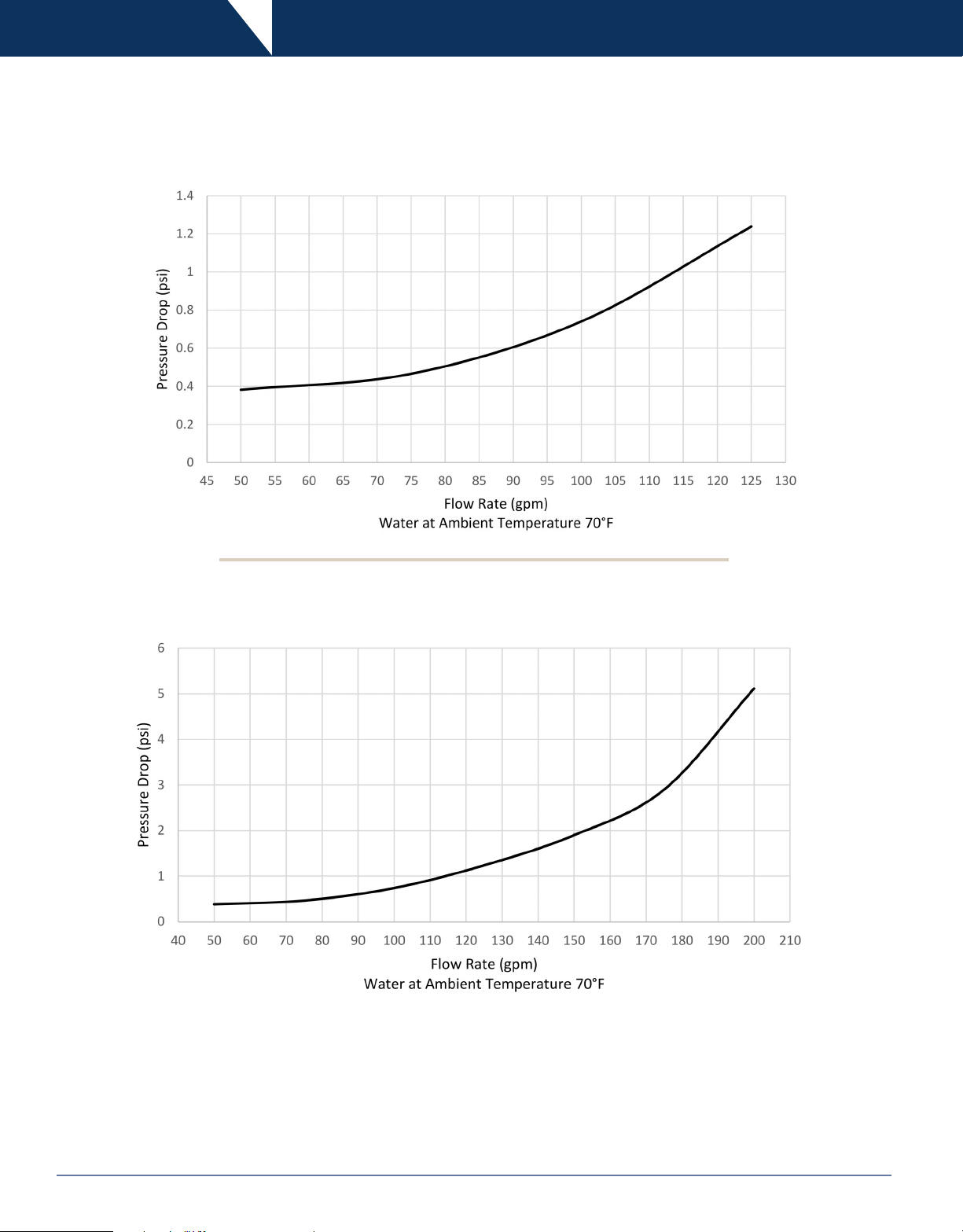
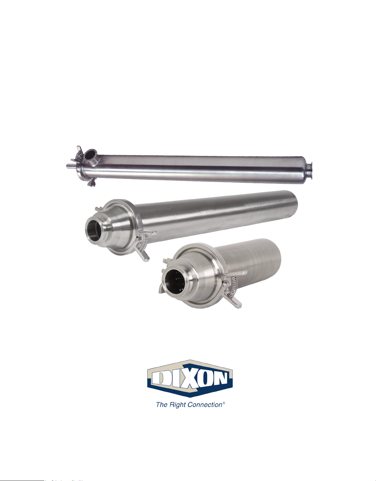
Technical Specications
Pressure Drop Chart - Short Strainers
Pressure Drop Chart - Long Strainers
6 Strainer I & O Manual 800.789.1718
 Loading...