

Instruction & Operation Manual
Read and understand this manual prior to
installing, operating or servicing this equipment
BC/BP-Series Centrifugal Pump
Updated March 2018
2 Instruction & Operation Manual800.789.1718
Table of Contents
Safety ...........................................................2
Care of Stainless Steel .................................3
Introduction ...................................................4
Mechanical Specications ............................5
Dimensions ............................................... 6-7
Installation .............................................. 8-15
Unpacking .............................................8
Tools needed .........................................8
'D' seal pump assembly ..................... 8-9
'DG' seal pump assembly ...............10-11
BP-Series Impeller Installation ............11
Location ...............................................12
Leveling ...............................................12
Piping guidelines ........................... 13-15
General ........................................13
Suction ................................... 13-14
Discharge .....................................14
Valve location ...............................15
Electrical .....................................................15
Safety Information
The following DANGER, WARNING and CAUTION signs are contained in this manual.
To avoid serious injury and/or possible damage to equipment, pay attention to these messages.
Hazards or unsafe practices which could result in severe personal injury or death. The word
DANGER is used in the most extreme cases.
Hazards or unsafe practices which could result in minor or moderate injury.
May also be used to alert against an unsafe operating or maintenance practice.
Indicates a potentially hazardous situation which, if not avoided, could result in
death or serious injury.
Use only replacement parts and devices recommended by the manufacturer to maintain the
integrity of the equipment. Make sure the parts are properly matched to the equipment series,
model, serial number and revision level of the equipment.
Safety labels are placed on every pump. Do not remove any labeling on any BC/BP-Series pump.
Replace any label that is missing.
DO NOT modify any Dixon Sanitary product. Non-factory modications could create hazardous
conditions and voids all warranties. DO NOT attempt to use a Dixon Sanitary product in any
application that exceeds the product rating.
Operation .............................................. 16-18
Priming the Pump .......................... 16-17
Starting the Pump................................18
Stopping the Pump ..............................18
Maintenance ......................................... 18-20
Scheduled Maintenance ......................18
Disassembly & Inspection ...................19
Seal Maintenance & Repair.................20
Troubleshooting .................................... 21-22
Model No.s & Part No.s ........................ 23-25
Pump model No.s ................................23
Part number key ..................................24
Common parts .....................................24
Variable parts ......................................25
Repair Kits ..................................... 26-27
ADDENDUM: Older Version Adapter
and Guard Assembly ..................... 28-34
Warranty .....................................................35

PUMP
3Instruction & Operation Manual 800.789.1718
Care of Stainless Steel
The stainless steel components in Dixon Sanitary equipment are machined, welded and assembled by skilled craftsmen using
manufacturing methods that preserve the corrosion-resistant quality of the stainless steel.
Retention of corrosion-resistant qualities under processing conditions requires regular attention to the precautions listed below.
1. Regularly check all electrical devices connected to the equipment for stray currents caused by improper
grounding, damaged insulation or other defects. Corrosion: Pitting often occurs when stray currents
come in contact with moist stainless steel.
2. Never leave rubber mats, ttings, wrenches, etc. in contact with stainless steel. Corrosion: Pitting or galvanic action. Objects
retard complete drying, preventing air from reforming the protective oxide lm. Galvanic corrosion occurs when two dissimilar
metals touch when wet.
3. Immediately rinse equipment after use with warm water until the rinse water is clear. Clean the equipment (manual or CIP)
as soon as possible after rinsing. Corrosion: discoloration, deposits, pitting. Product deposits often cause pitting beneath the
particles.
4. Use only recommended cleaning compounds. Purchase chemicals from reputable and responsible chemical manufacturers
familiar with stainless steel processing equipment, they continuously check the effects of their products on stainless steel.
5. Use cleaning chemicals exactly as specied by the manufacturer. Do not use excessive concentrations, temperatures or
exposure times. Corrosion: Pitting, discoloration, stress cracks. Permanent damage often occurs from excessive chemical
concentrations, temperatures or exposure times.
6. For manual cleaning, use only soft non-metallic brushes, sponges or pads. Brush with the grain on polished surfaces, avoid
scratching the surface. Corrosion: Pitting, scratches. Metal brushes or sponges will scratch the surface and promote corrosion
over a period of time. Metal particles allowed to remain on a stainless steel surface will cause pitting.
7. Use chemical bactericides exactly as prescribed by the chemical manufacturer in concurrence with local health authority. Use
the lowest permissible concentration, temperature and exposure time possible. Flush immediately after bacterial treatment.
In no case should the solution be in contact with stainless steel more then 20 minutes. Corrosion: Protective lm destroyed.
Chlorine and other halogen bactericides can destroy the protective lm. A few degrees increase in temperature greatly
increases chemical activity and accelerates corrosion.
8. Regularly inspect the joints in pipelines. Be sure all connections are tight tting without binding. Corrosion: Crevice corrosion.
Small crevices caused by improperly seated gaskets will promote crevice corrosion. Stainless steel under stress will develop
stress cracking especially in the presence of bactericides containing chlorine.
9. Regularly inspect equipment for surface corrosion (i.e. pitting deposits, stress cracks, etc.). If deposit or color corrosion is
detected, remove it immediately using mild scouring powder and detergents. Rinse thoroughly and allow to air dry. Review
production and cleaning procedures to determine the cause. Note: If corrosion is not removed, the protective lm cannot be
restored and corrosion will continue at an accelerated rate.
4 Instruction & Operation Manual800.789.1718
Introduction
This manual contains installation, operation, cleaning, repair instructions, model numbering structure and parts list for the Dixon
Sanitary BC/BP-Series centrifugal pumps.
The Dixon Sanitary BC/BP-Series centrifugal pump is made up of two sections: the pump components (uid end) and the motor
assembly. The pump is mounted on the drive motor with an adapter and is coupled to the motor with a stainless steel stub shaft. The
pump impeller on the BC-Series is mounted on the stub shaft and is secured with a oating impeller retainer pin. The pump impeller
on the BP-Series is secured with a threaded impeller nut.
The casing is joined to the adapter by a heavy duty cast clamp. This design allows the casing outlet to be rotated to various
positions.
An adjustable leg kit is an option for mounting to the motor and is designed to meet sanitary requirements. This conguration
simplies the installation and ease of leveling.
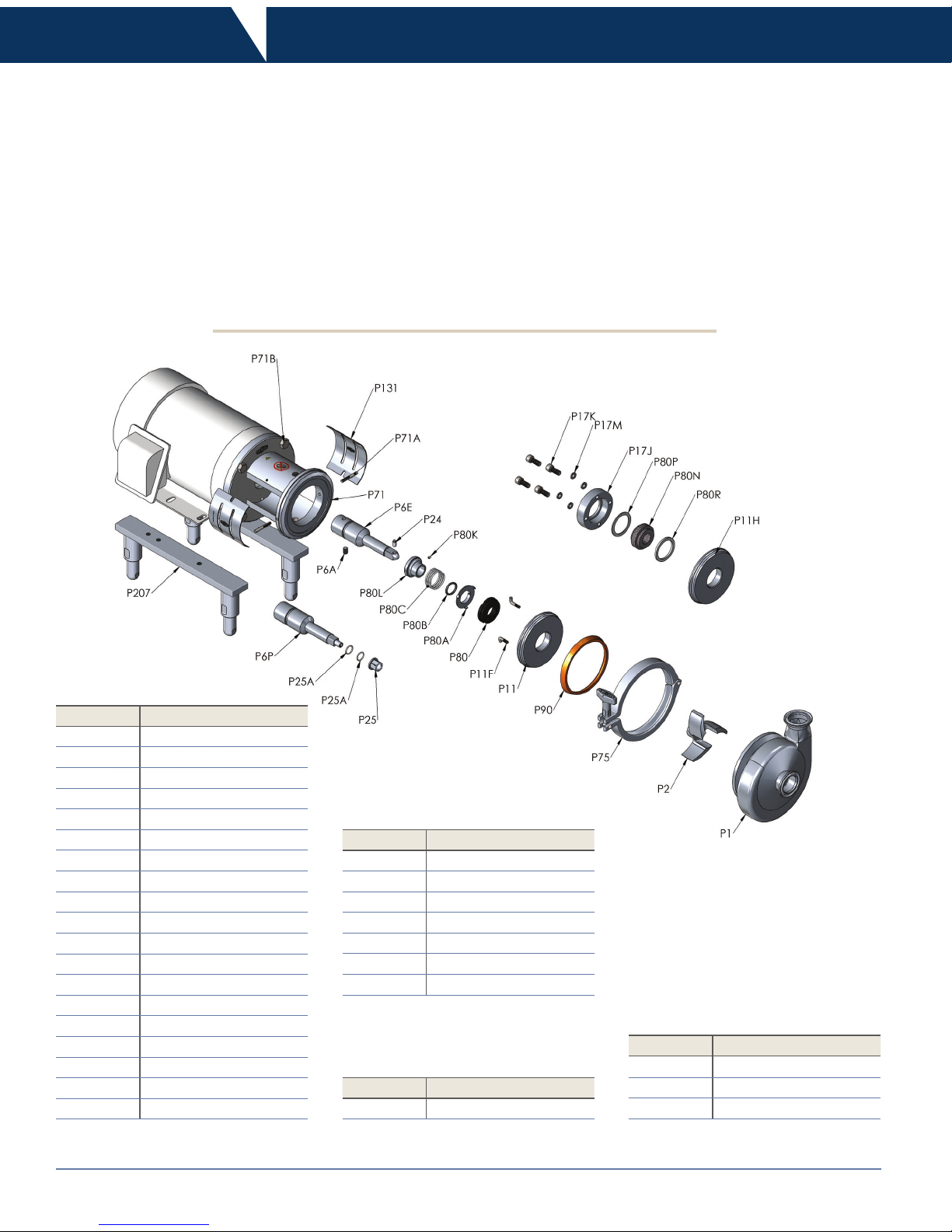
Key No. Description
P1 Casing
P2 Impeller
P6A Shaft Set Screws
P6E Stub Shaft
P11 'D' Back Plate
P11F Back Plate Pins *
P24 Impeller Retainer
P71 Adapter
P71A Adapter Pins *
P75 Clamp Assembly
P80 Carbon Seal
P80A Seal Cup
P80B Seal O-ring
P80C Spring
P80K Seat Screw
P80L Drive Collar
P90 Casing Gasket
P131 Guard Set
P207 Leg Kit
Key No. Description
P11H 'DG' Back Plate
P17J Gland Ring
P17K Gland Bolt
P17M Washers
P80N Seal Seat
P80P Outboard Gasket
P80R Inboard Gasket
DG Seal
* not used on BC114/214 DG Models
** used for cascade seal option
Key No. Description
P5 F Seal Fitting **
F Seal
Key No. Description
P6P Stub Shaft
P25 Impeller Nut
P25A Impeller O-ring
BP Threaded Impeller Nut
PUMP
5Instruction & Operation Manual 800.789.1718
Mechanical Specications
• Motor: standard C-face, 1750 and 3450 RPM, TENV/TEFC
and washdown, foot mounted
• Additional motor types available upon request
• Mounting: pump head mounted to a C-Face motor
Motors and Mounting
• Nominal Capacity: up to 1200 GPM
• Temperature: 32°F to 212°F, consult Dixon Sanitary for other
temperatures
• Nominal speed: up to 3500 RPM - 60 Hz
Performance Characteristics
• Casing: 316L stainless steel
• Impeller: CF8M (316) stainless steel
• Backplate: 316L stainless steel
• Stub Shaft: 316L stainless steel
• Adapter: 304 stainless steel
• Optional Leg Kit: 304 stainless steel
• Seal Types: externally balanced 'D', 'DG' and 'F' with clamped
in seat
• Rotary Seal Material: carbon and silicon carbide
• 'DG' Seal Seat Material: silicon carbide, ceramic and tungsten
carbide
• Elastomers: Buna, EPDM, silicone and FKM
• Finish: sanitary polish 32RA
Standard Construction
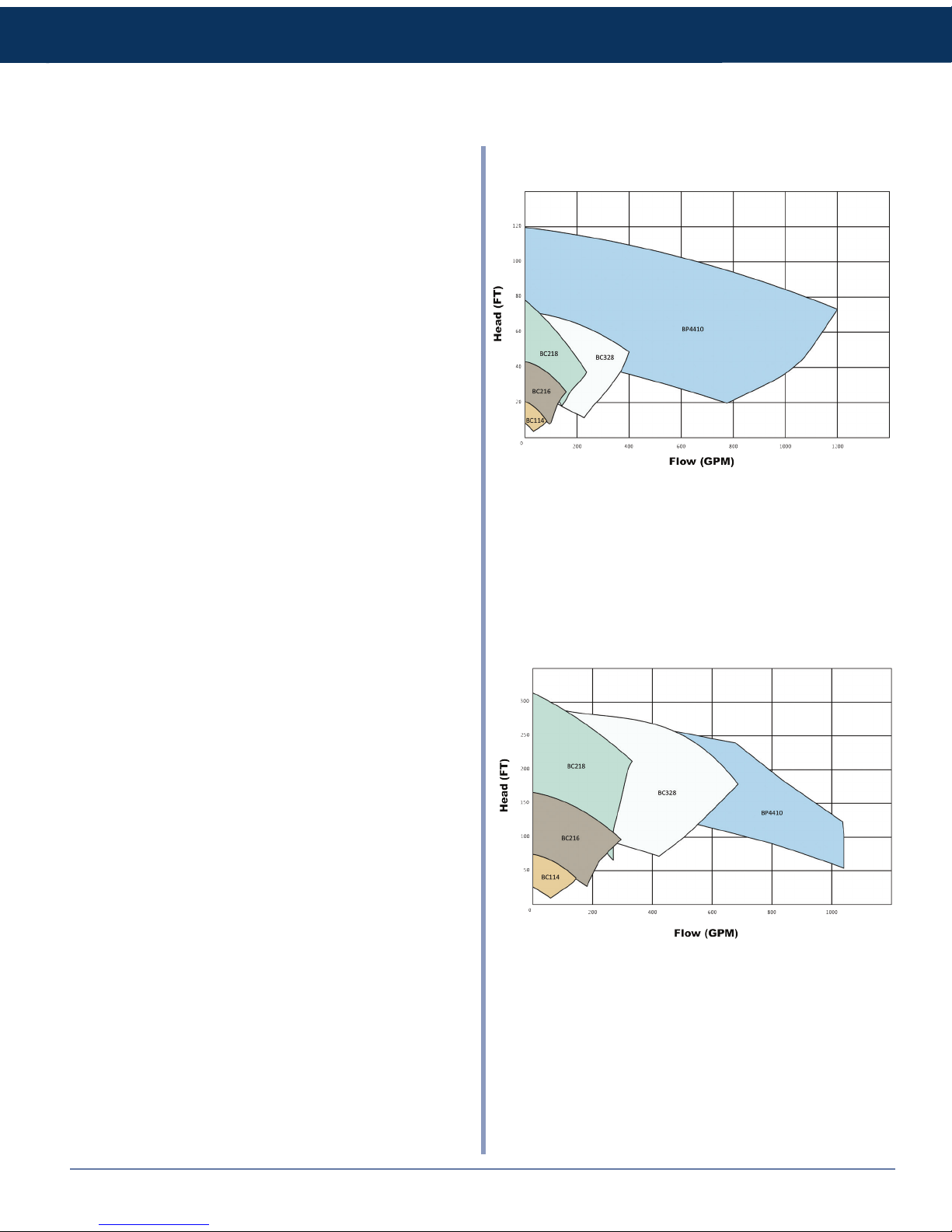
3500 RPM
1750 RPM
6 Instruction & Operation Manual800.789.1718
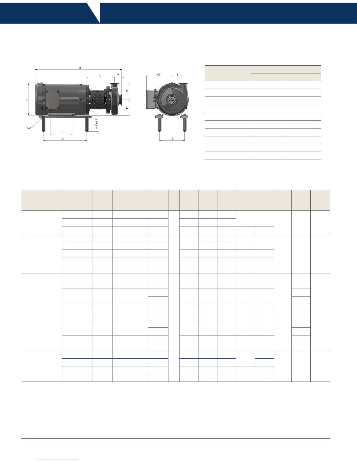
Dimensions
All dimensions are given in inches
* only applies to the BC/BP 328/428
** contact Dixon Sanitary for exact measurement
Pump Model
Connection Sizes
Inlet Outlet
BC[BP]114 1.50 1.50
BC[BP]214 2.00 1.50
BC[BP]216 2.00 1.50
BC[BP]516 2.50 1.50
BC[BP]218 2.00 1.50
BC[BP]318 3.00 1.50
BC[BP]328 3.00 2.00
BC[BP]428 4.00 2.00
BP441 4.00 4.00
BP641 6.00 4.00
Pump
Model
Frame
Size
A
AA
(Conduit
Size)
AB B D E F L P X Y Z
BC/BP 114
BC/BP 214
56C 8.50 0.50 5.00
**
3.50 4.88 3.00
6.22 6.63
3.63 1.63 2.63143/145TC 9.50 0.75 5.25 5.50 4.00
182/184TC 10.63 0.75 5.88 4.50 7.50 4.50 6.78 7.88
BC/BP 216
BC/BP 516
56C 8.50 0.50 5.00
**
3.50
4.88 3.00
6.06 6.63
4.50 1.94 3.69
143/145TC 9.50 0.75 5.25 5.50 4.00
182/184TC 10.63 0.75 5.88 4.50 7.50 4.50 6.69 7.88
213/215TC 13.88 1.00 7.38 5.25 8.50 5.50 7.81 9.56
254/256TC 18.00 1.00 9.63 6.25 10.00 8.25 8.50 12.94
BC/BP 218/318
BC/BP 328/428
182/184TC 10.63 0.75
5.88
**
4.50 7.50 4.50 6.94 7.88
5.50
1.94
4.75
5.88 2.25 *
213/215TC 13.88 1.00
7.38
5.25 8.50 5.50 7.31 9.56
1.94
7.38 2.25 *
254/256TC 18.00 1.00
9.63
6.25 10.00 8.25 8.19 12.94
1.94
9.63 2.25 *
284/286TC 19.00 1.50
13.13
7.00 11.00 9.50 8.81 14.63
1.94
13.13 2.25 *
324/326TC 20.50 2.00
14.13
8.00 12.50 10.50 9.69 16.50
1.94
14.13 2.25 *
BP4410
BP6410
213/215TC 13.88 1.00 7.38
**
5.25 8.50 5.50
10.53
9.56
7.35 3.25 7.60
254/256TC 18.00 1.00 9.63 6.25 10.00 8.25 12.94
284/286TC 19.00 1.50 13.13 7.00 11.00 9.50 11.16 14.63
324/326TC 20.50 2.00 14.13 8.00 12.50 10.50 10.53 16.50
PUMP
7Instruction & Operation Manual 800.789.1718
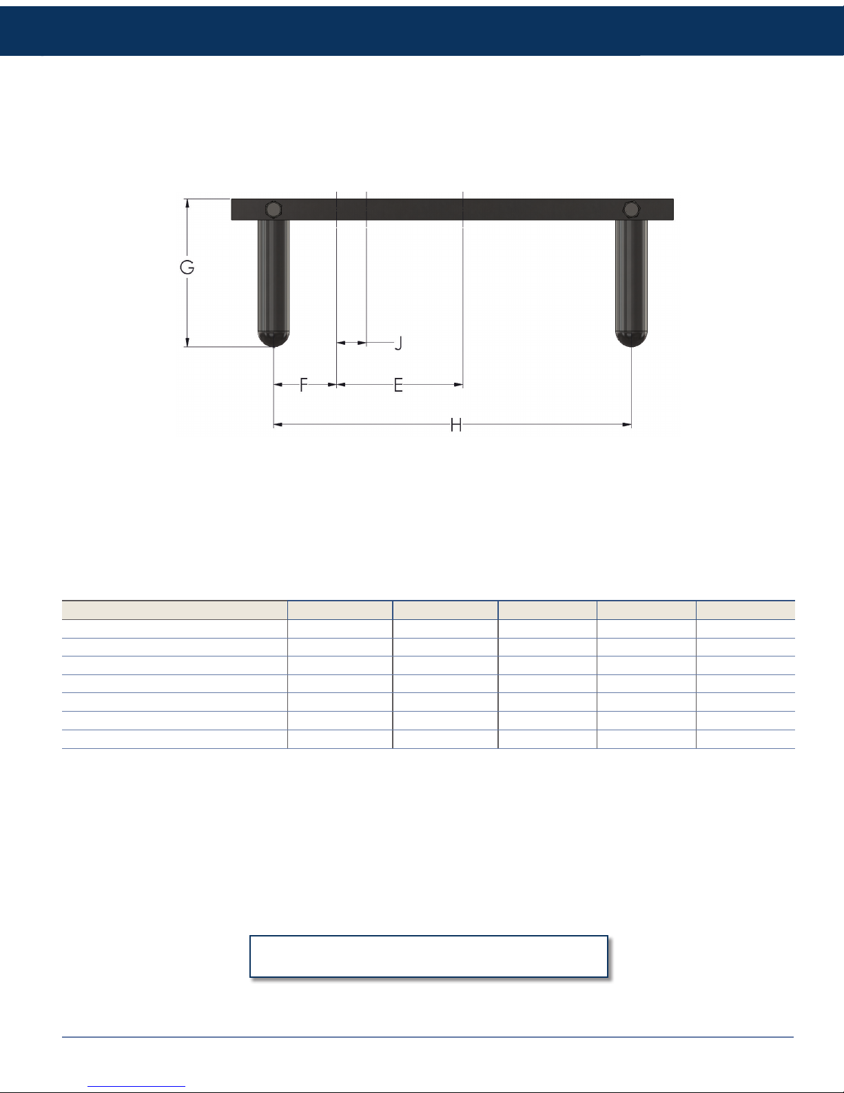
Dimensions
Frame Size E F G H J
56C 3.00 1.50 5.00 8.50 NA
140TC 5.00 1.50 5.00 9.50 1.00
180TC 5.50 1.50 5.00 10.63 1.00
210TC 7.00 1.50 5.00 13.88 1.50
250TC 10.00 1.50 5.00 18.00 1.75
280TSC 11.00 1.50 5.00 19.00 1.50
320TSC 12.00 1.50 5.00 20.50 1.50
All dimensions are approximate;
for exact dimensions contact Dixon Sanitary
All dimensions are given in inches
8 Instruction & Operation Manual800.789.1718
Installation
Unpacking
Carefully unpack all parts of the pump and inspect for damages that may have occurred during shipment. Report any damages to the
carrier immediately.
The ports on the pump are protected with a plastic cover. If any covers are missing or damaged, inspect the ports on the pump
thoroughly for any damage.
Tools Needed
If you have purchased a uid end and will be assembling the pump to a motor the following tools will most likely be used:
'D' Seal Pump Assembly
• Flat head screw driver
• Allen wrenches
• Open ended wrenches
• Feeler gauge
• Calipers
• Pliers
• Rubber mallet
1. Install the adapter onto the motor using (4) bolts and (4) lock washers.
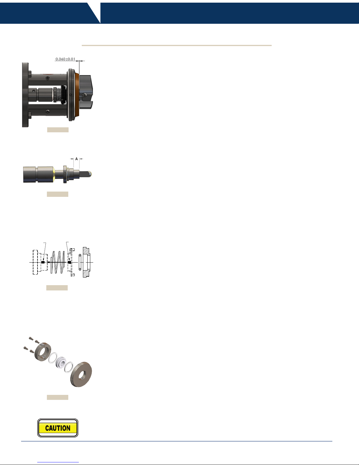
2. Stub shaft alignment:
a. Make sure that the key is in the motor shaft, then slide stub shaft onto motor shaft. Do not
tighten set screws.
b. Set back plate on adapter face.
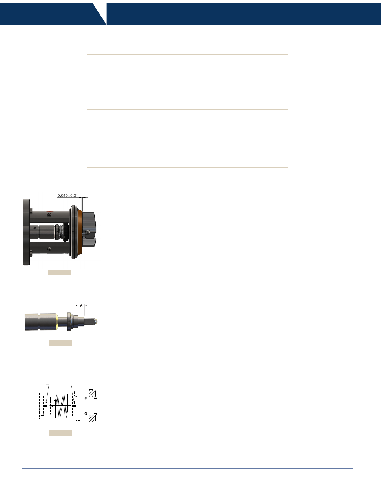
c. Slide impeller onto stub shaft end.
d. Using feeler gauge between back plate and impeller position stub shaft so that the gap is
equal to .060"
± .010
. (see gure no.1)
e. Add thread locker to shaft set screws and tighten set screws to stub shaft.
f. Remove impeller and back plate.
3. Slide drive collar large end rst over the stub shaft. Position collar and set dimension 'A' to
0.6". (see gure no.2)
4. Tighten collar set screws.
a. Place seal spring over stub shaft and down onto the drive collar.
b. Place cup on the top of the spring and rotate the cup until the tab on the bottom of the cup
abuts the end of the spring coil. Line the notch in the cup with the extrusion pin on the drive
collar. (see gure no. 3)
c. Place seal O-ring into the back of the carbon seal and slide the seal O-ring assembly onto
stub shaft, lining the notches in the carbon seal up with the pins on the cup.
d. Check to make sure that slot in cup is still aligned with the extrusion in the drive collar.
(see gure no.3)
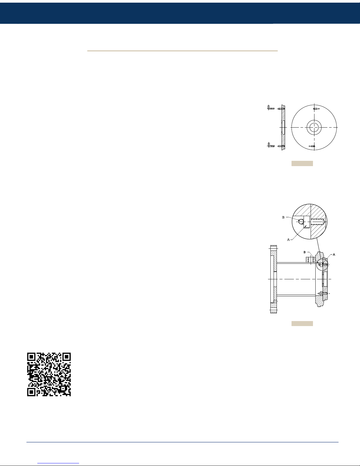
5. Screw back plate pins into back plate. (see gure no.4)
6. Position casing gasket on circumference of the back plate.
7. Check that both the seal face on the back plate and the seal face of the carbon seal are
completely clean. Even the oils from your skin are not acceptable on these two surfaces.
Clean faces thoroughly with a clean, lint free cloth.
continued on next page ...
COLLAR
EXTRUSION
CUP
SLOT
Figure No. 1
Figure No. 2
Figure No. 3
PUMP
9Instruction & Operation Manual 800.789.1718
8. Assemble back plate to adapter.
a. Place the back plate assembly onto the adapter. Put even pressure down on the back plate
until it is completely seated on the adapter. (see gure no.5)
b. Check that the drive collar extrusion is fully engaged in the slot on the cup.
c. Rotate the back plate so that the back plate pins engage the adapter pins, holding it in
place.
d. With back plate depressed completely to the adapter, inspect the spring to ensure there is
some space between the coils. If the coil is too tight, repeat step 5 and add 0.05" to
dimension 'A' and re-check spring coil. Repeat if necessary.
9. Install the impeller.
a. Insert the impeller retainer into the hole near the end of the stub shaft so that it is centered
in the shaft.
b. Slide the impeller onto the stub shaft.
c. Using a small hex key or screw driver push the impeller retainer so that it is sticking out one
end as far as it will allow, thus locking the impeller into place.
10. Close and seal the pump.
a. Place casing onto assembly with casing outlet pointing in the desired position.
b. While applying sufcient pressure to bring adapter and casing together put on and tighten
clamp. Wing nut tightened to 25 lb. of torque.
11. Attach guards to both sides of the pump adapter. Tighten guard fasteners to ensure that the
guards are securely in place.
Installation
'D' Seal Pump Assembly
... continued from previous page
A
B
A
B
Figure No. 4
Figure No. 5
Scan this code on
your smart phone to
visit the YouTube
video for detailed
assembly instructions
10 Instruction & Operation Manual800.789.1718
Installation
'DG' Seal Pump Assembly
1. Install the adapter onto the motor using (4) bolts and (4) lock washers. For BP441 and 641
models add adapter pins.
2. Stub shaft alignment:
a. Make sure that the key is in the motor shaft, then slide stub shaft onto motor shaft. Do not
tighten set screws.
b. Set back plate on adapter face.
c. Slide impeller onto stub shaft end.
d. Using feeler gauge between back plate and impeller position stub shaft so that the gap is
equal to .060"
± .010
. (see gure no.6)
e. Add thread locker to shaft set screws and tighten set screws to stub shaft.
f. Remove impeller and back plate.
3. Slide drive collar large end rst over stub shaft until it will not slide any further. For BP441 and
641 models, position collar and set dimension 'A' to 1.65". (See gure no. 7)
4. Tighten collar set screws.
a. Place seal spring over stub shaft and down onto the drive collar.
b. Place cup on the top of the spring and rotate the cup until the tab on the bottom of the cup
abuts the end of the spring coil. Line the notch in the cup with the extrusion pin on the drive
collar. (see gure no. 8)
c. Place seal O-ring into the back of the carbon seal and slide the seal O-ring assembly onto
stub shaft, lining the notches in the carbon seal up with the pins on the cup.
d. Check to make sure that slot in cup is still aligned with the extrusion in the drive collar.
(see gure no.8)
5. Assemble 'DG' seal back plate. (see gure no.9)
6. Position casing gasket on circumference of the back plate.
7. Check that both the seal face on the back plate and the seal face of the carbon seal are
completely clean. Even the oils from your skin are not acceptable on these two surfaces.
Clean faces thoroughly with a clean, lint free cloth.
8. Assemble back plate to adapter.
a. Place the back plate assembly onto the adapter. Put even pressure down on the back plate
until it is completely seated on the adapter.
b. Check that the drive collar extrusion is fully engaged in the slot on the cup.
9. Install the impeller.
a. Insert the impeller retainer into the hole near the end of the stub shaft so that it is centered
in the shaft.
b. Slide the impeller onto the stub shaft.
c. Using a small hex key or screw driver push the impeller retainer so that it is sticking out one
end as far as it will allow, thus locking the impeller into place.
10. Close and seal the pump.
a. Place casing onto assembly with casing outlet pointing in the desired position.
b. While applying sufcient pressure to bring adapter and casing together put on clamp. Wing
nut tightened to 25 in. lb. of torque. For BP441 & 641 models with bolted clamp, all nuts are
tightened to 20 ft. lb. of torque.
11. Attach guards to both sides of the pump adapter. Tighten guard fasteners to ensure that the
guards are securely in place.
Figure No. 6
COLLAR
EXTRUSION
CUP
SLOT
Figure No. 8
Figure No. 9
Figure No. 7

PUMP
11Instruction & Operation Manual 800.789.1718
Installation
BP-Series Impeller Installation
D-Seal
Replace Step 9 on page 9 with the following:
11. Install the impeller.*
a. Slide the impeller onto the stub shaft.
b. Place the impeller nut O-ring onto the stub shaft.
c. Thread the impeller nut and torque as per the ratings.
DG-Seal
Replace Step 9 on page 10 with the following:
10. Install the impeller.*
a. Slide the impeller onto the stub shaft.
b. Place the impeller nut O-ring onto the stub shaft.
c. Thread the impeller nut and torque as per the ratings.
* For 441/641 models
a. Place the impeller O-ring onto the stub shaft.
b. Slide the impeller onto the stub shaft.
c. Place the impeller nut O-ring onto the stub shaft.
d. Thread the impeller nut and torque as per the ratings.
Pump Model In Lbs.
114 100
216 210
218/328 350
4410 450
BP-Series Threaded Impeller Nut Torque Ratings
Scan this code on
your smart phone to
visit the YouTube
video for detailed
assembly instructions

12 Instruction & Operation Manual800.789.1718
• Pump will perform at its best when located as close as possible to the liquid supply.
• Supply piping should be short and straight to ensure the pump has an adequate supply of liquid to it at all times.
• The pump should be located in an area where it is easy to inspect and do preventative maintenance or repair.
Location
The pump can be easily leveled by installing the optional leg kit.
Loosen the set screws and adjust the leg to the proper level,
then tighten the set screws when level. (see the diagram at right)
Optional Leg Kit Installation and Leveling
Scan this code on
your smart phone to
visit the YouTube
video for detailed
assembly instructions
Installation

PUMP
13Instruction & Operation Manual 800.789.1718
Installation
Piping: General Guidelines
Improper piping can lead to a number of problems
with pump performance which could lead to increased
maintenance costs.
• Ensure piping is independently supported at both the suction
and discharge ports of the pump. (see the diagram at right)
• Piping must be properly aligned to prevent any strain on
pump casing.
• Try to have as few bends as possible in all piping.
Piping: Suction Guidelines
• Make sure line sizes used are equal to or larger than suction side (supply side) port connections on the pump.
• Suction side needs to be as short and straight as possible. Any restrictions will affect the NPSHa. Adequate NPSHa must be
ensured.
• Maintain a straight length of pipe at a minimum of 8 x diameters long at the pump inlet. (see the diagram below)
PROXIMITY
TO
VOLUTE
TUBING
HANGER
TUBING
HANGER
DIAMETER
MINIMUM LENGTH = 8 x DIAMETER
continued on next page ...

14 Instruction & Operation Manual800.789.1718
• To prevent air leaks, ensure all joints in suction line are well
sealed.
• Use an eccentric reducer with straight side up to prevent air
pockets from forming which will result in a decrease in pump
efciency. (see the diagram at right)
• To prevent a high point in the suction line resulting in an air
pocket being formed affecting proper pump performance,
horizontal suction pipes must have a gradual rise to the
pump.
Installation
Piping: Suction Guidelines
Piping: Discharge Guidelines
• Discharge side should be short and direct. Use a minimal number of restrictions.
(see the diagram to the right)
• Vertical or top horizontal pump discharge position is preferred.
(see the diagram at the bottom)
• While increasing the discharge side line size is recommended, please note:
> Using too large of a line size may lead to motor overload and cavitation.
> Using a smaller than recommend line size will increase the pump head but lower the ow.
• Types of reducers to use:
> If vertical discharge – concentric
> If horizontal discharge – eccentric with straight side down
... continued from previous page
ECCENTRIC
REDUCER
CONCENTRIC
REDUCER
DIAMETER
MINIMUM LENGTH
= 10 x DIAMETER
BETWEEN
0° & 90°

PUMP
15Instruction & Operation Manual 800.789.1718
• An isolation valve should be installed at both the suction and
discharge sides of the pump. This will allow you to remove
the pump for preventative maintenance or repair without the
need to drain your system.
(see the diagram to the right)
• If pump is not in a ooded suction condition, install either a
foot valve or system check valve to ensure pump casing is
ooded for priming.
• In order to provide pump ow rate control, a control valve
should be installed in the discharge piping to prevent motor
overload.
Installation
Piping: Valve location
All power must be off and locked out during the installation process.
Only registered electricians should do the electrical installation.
Electrical
• Follow motor manufacturer’s installation procedures.
• Verify motor nameplate data is compatible with existing
electrical supply.
• Verify pump rotation. An arrow sticker is supplied with every
pump to show correct pump rotation. If the arrow stickers are
missing, contact Dixon Sanitary for a replacement.
• Correct rotation is counter clockwise when facing pump inlet
connection.
MINIMUM LENGTH
= 10 X DIAMETER
DIAMETER
CHECK
VALVE
CONTROL
VALV E
MINIMUM LENGTH = 8 X DIAMETER
DIAMETER
ISOLATION
VALVE
PSI

16 Instruction & Operation Manual800.789.1718
Operation
Priming the Pump
SUPPLY SOURCE
ABOVE PUMP LEVEL
CHECK
VALVE
CONTROL
VALV E
ISOLATION
VALVE
To avoid damage to the pump, the pump casing must be ooded with liquid
BEFORE starting the pump.
Fluid supply above the pump:
1. Open supply line isolation valve.
2. Vent any entrapped air by opening the discharge valve.
3. After casing is ooded, start pump.
If the uid supply is below the pump see page 17.
Note: This is not a self priming pump. Other means must be installed to prime the pump.

PUMP
17Instruction & Operation Manual 800.789.1718
Operation
Priming the Pump
CHECK
VALVE
CONTROL
VALV E
ISOLATION
VALVE
FOOT
VALV E
EXTERNAL PRIMING
SUPPLY LINE
Fluid supply below the pump:
1. Close discharge valve and open air vents.
2. Open valve in external priming supply line. Close once liquid
ows from vent valves.
3. Close vent valves.
4. Turn off priming supply line.
5. Start pump.
If the uid supply is above the pump see page 16.
Note: It is recommended to use a foot/check valve system to keep the pump primed. Otherwise the pump must be primed before
each operation.

18 Instruction & Operation Manual800.789.1718
Operation
Starting the Pump
1. Ensure pump suction is ooded using either method as explained in the previous priming section.
2. Check for any closed valves or obstructions in the suction and discharge lines.
3. Start the motor.
4. Verify liquid is owing and there is no piping connection or mechanical seal leaks.
5. Adjust throttling valve on discharge line to desired ow.
Stopping the Pump
1. Shut off power to motor.
2. Suction and discharge valves are to be shut off.
Be advised the pump does not act as a shut off valve. The liquid will ow freely though the pump.
Maintenance
Scheduled Maintenance
Preventative maintenance will increase the life of your pump. Documentation of any maintenance will help to diagnose potential
problems and help in determining solutions.
1. Inspect casing for:
• Unusual wear
• Damage to ports
2. Inspect casing gasket for
• Wear
• Damage
3. Inspect impeller for
• Unusual wear
• Damage
Scheduled maintenance will require disassembly of the pump and the following:
4. Inspect mechanical seal for wear
5. Inspect shaft for
• Straightness
• Tightly installed
• Unusual pump or motor noise
• Excessive vibration
• Seal leakage
• Piping leaks at ports
Monitor pump during operation for any of the following problems:
• Unexpected change in ow or head
• Temperature changes
• Excessive power consumption
• Overheating motor
6. BP- Series
If the threads have a soiled appearance,
replace the two O-rings P25A. Inspect
the threads in the impeller nut and
on the end of the stub shaft (P6P). If
there is any evidence of soil or dirtied
appearance, completely disassemble
the stub shaft and nut. Clean all the
threads and surfaces of the shaft and
nut by manual brushing in a bath of
cleaning solution (Acid detergents or
simple alkaline soda type detergents).
After cleaning, rinse the shaft and nut
thoroughly with water.
See troubleshooting guide on pages 21-22, for possible solutions.

PUMP
19Instruction & Operation Manual 800.789.1718
Maintenance
Disassembly & Inspection
1. Turn off and lock out power to pump motor.
2. Isolate pump from system.
3. Relieve system pressure.
4. Remove suction and discharge lines from casing.
5. Remove adapter guards.
6. Loosen clamp assembly and remove.
7. Remove casing and inspect for unusual wear or port damage.
8. For BC-Series push back impeller and center impeller retainer in the stub shaft. For BP-Series remove impeller nut and O-ring.
9. Remove impeller and inspect for unusual wear or damage.
10. Remove impeller retainer.
11. Rotate back plate to disengage from adapter pins and remove.
12. See seal removal and inspection instructions on page 20.
13. Inspect shaft to ensure straightness and that it is fastened securely to the motor shaft.
14. If necessary remove stub shaft by loosening the two (2) set screws. If the shaft does not remove easily, use a pry bar on the
periphery of the base of the shaft.
Scan this code on
your smart phone to
visit the YouTube
video for
BC-Series Disassembly D-Seal
Scan this code on
your smart phone to
visit the YouTube
video for
BC-Series Disassembly DG-Seal

20 Instruction & Operation Manual800.789.1718
Maintenance
Seal Maintenance & Repair
See page 19 for disassembly instructions.
'D' Seal
1. When removing back plate inspect the stationary seal seat area for wear and/or damage.
Depending upon the extent of wear, the back plate may need to be resurfaced or replaced.
2. Remove the carbon seal, O-ring, cup and spring.
3. Inspect carbon seal. Replace carbon seal if "A" dimension is less than 1/32".
(see the diagram to the right)
4. If carbon seal is replaced, drive collar setting should be veried and adjusted as needed.
'DG' Seal
1. When removing back plate inspect for any nicks or scratches.
2. Remove the four (4) bolts from the gland assembly.
3. Inspect 'DG' seal seat. This is a reversible part and if there is wear on one side you can ip it
to the other side until that side is worn.
4. Inspect gland ring and gaskets. Replace as needed.
5. Remove the carbon seal, O-ring, cup and spring.
6. Inspect carbon seal. Replace carbon seal if "A" dimension is less than 1/32".
(see the diagram to the right)
Return to disassembly instructions on page 19.
Scan this code on
your smart phone to
visit the YouTube
video for
BC-Series Repair Kit #1
Scan this code on
your smart phone to
visit the YouTube
video for
BC-Series Repair Kit #3
Scan this code on
your smart phone to
visit the YouTube
video for
BC-Series Repair Kit #4
Scan this code on
your smart phone to
visit the YouTube
video for
BC-Series DG Repair Kit

PUMP
21Instruction & Operation Manual 800.789.1718
Troubleshooting
Dixon Sanitary BC-Series pumps are manufactured and inspected to meet sanitary standards. Occasional problems may arise.
The following guide will help determine the possible cause and offer suggestions on corrections to maximize the performance of
your pump. In case of any electric motors issues, contact the motor manufacturer directly. If you have any questions or concerns in
regards to your BC-Series pump, we encourage you to contact Dixon Sanitary.
PROBLEM POSSIBLE CAUSE SUGGESTED ACTION
Not enough or no discharge No uid reaching pump. Need to prime pump. Installation of a priming system is
recommended.
Suction or discharge closed or
blocked.
Open suction. If plugged, shutdown pump and remove blockage.
If closed, check all valves for proper positions.
Motor rotation incorrect. Adjust motor electrical wiring to correct rotation.
Speed too slow (low voltage,
wrong frequency, wrong motor).
Adjust voltage and frequency. Change motor if necessary.
Impeller damaged. Replace impeller.
Seal area or supply area has an
air leak.
Replace seal if needed. Check all other areas for air leaks and
repair.
Excessive air in material. Make any adjustments in system to ensure excess air is
removed before material reaches the pump.
Discharge head too high. Adjust system to lower discharge head.
Suction lift too high. Adjust system to lower suction lift.
Insufcient NPSH (Net Positive
Suction Head) available.
Adjust system to provide correct NPSHa.
Impeller diameter not correct for
application.
Contact: Dixon Sanitary 800-789-1718
Not Enough Pressure Seal area or supply area has an
air leak.
Replace seal if needed. Check all other areas for air leaks and
repair.
Motor rotation incorrect. Adjust motor electrical wiring to correct rotation.
Speed too slow (low voltage,
wrong frequency, wrong motor).
Adjust voltage and frequency. Change motor if necessary.
Excessive air in material. Make any adjustments in system to ensure excess air is
removed before material reaches the pump.
Impeller diameter not correct for
application.
Contact: Dixon Sanitary 800-789-1718
Motor Overload/Excessive
Power Consumption
Discharge is too high. Restrict discharge to lower ow rate.
Impeller is binding. Inspect pump and check for any damage, misalignment or
interference. Replace any damaged or worn parts.
Seal binding. Inspect pump and replace any damaged or worn parts.
Discharge is too low. Increase discharge head.
Liquid is heavier or more viscous
than rating.
Contact: Dixon Sanitary 800-789-1718
Electrical supply, voltage or
frequency incorrect.
Make any adjustments needed up to replacing the motor.
Faulty electrical connections. Check wiring and repair/replace as necessary.
Overload heaters too small. Inspect and replace as necessary.
Defective motor. Contact motor manufacturer for possible warranty or repair.
Replace if needed.

22 Instruction & Operation Manual800.789.1718
PROBLEM POSSIBLE CAUSE SUGGESTED ACTION
Excessive Vibration/Pump is
Noisy
Pump not level. Inspect installation of pump and correct level.
Non-supported piping. Verify piping support follows recommendations in installation
portion of this manual.
Not enough or no material
reaching pump.
Inspect pump to verify there is no blockage. Inspect suction line
and shorten or enlarge.
Insufcient NPSH (Net Positive
Suction Head) available.
Adjust system to provide correct NPSHa.
Impeller and/or shaft worn. Replace worn parts.
Shaft loose or bent. Readjust shaft settings, tighten shaft screws if loose. If bent,
replace shaft and inspect impeller hub for uneven wear, replace
impeller if worn.
Impeller out of balance. Inspect shaft if loose or bent. If impeller damaged, replace.
Foreign material in pump. Remove any foreign material and replace any worn or damaged
parts.
Excessive air in material. Make any adjustments in system to ensure excess air is
removed before material reaches the pump.
Motor bearings worn. Replace any worn ports or replace motor if needed.
Rapid Seal Wear Improper installation of
mechanical seal.
Adjust mechanical seal installation. Replace any worn or
damaged parts.
Dry running. Material must be in contact with seal at all times. Catastrophic
failure will occur.
Abrasive product. Contact: Dixon Sanitary 800-789-1718
Shaft loose or bent. Readjust shaft settings, tighten shaft screws if loose. If bent,
replace shaft and inspect impeller hub for uneven wear, replace
impeller if worn.
Water hammer. Correct system to prevent any quick starts and stops.
Improper seal for application. Contact: Dixon Sanitary 800-789-1718
Pump Leaks Inlet/Outlet Inspect for missing union gaskets, loose connections or
damaged ports. Replace worn gaskets and tighten loose
connections. Damaged ports repair or replace.
Casing clamp loose. Tighten clamp.
Casing gasket damaged or worn. Replace gaskets.
Seal not installed correctly. Reassemble seal properly. Replace any worn or damaged parts.
Carbon seal worn or damaged. Replace any worn or damaged parts.
'D' seal back plate worn. Resurface or replace. "DG" option should be considered.
Any Other Issue Contact: Dixon Sanitary 800-789-1718
Troubleshooting

PUMP
23Instruction & Operation Manual 800.789.1718
Model No.'s & Part No.'s
Pump Models
Fluid end includes all parts required to assemble to your motor.
Specify adjustable leg kits at time of order. Leg kits will be shipped to match the frame size of motor as specied by
model number. Leg kits will not be assembled.
Please note, if there are options that are not listed above, please contact Dixon Sanitary (800.789.1718) for
availability and pricing.
Fluid End
Model No.
114 – 1.5 x 1.5
214 – 2 x 1.5
216 – 2 x 1.5
516 – 2.5 x 1.5
218 – 2 x 1.5
318 – 3 x 1.5
328 – 3 x 2
428 – 4 x 2
441 * – 4 x 4
641 * – 6 x 4
* only available
as a BP with
DG seal
Port Style
M – Clamp
B – Buttweld
Shaft Seal
1 – D Type
2 – DG SC
3 – DG CER
4 – DG TC
5 – D/F
6 – DG/SC/SC
7 – DG/SC/F
Impeller Size
01 – 2.5"
02 – 2.75"
03 – 3.0"
04 – 3.25"
05 – 3.50"
06 – 3.75"
07 – 4.0"
08 – 4.25"
09 – 4.50"
10 – 4.75"
11 – 5.0"
12 – 5.25"
13 – 5.50"
14 – 5.75"
15 – 6.0"
16 – 6.25"
17 – 6.5"
18 – 6.75"
19 – 7.0"
20 – 7.25"
21 – 7.50"
22 – 7.75"
23 – 8.0"
70 – 8.25"
71 – 8.50"
72 – 8.75"
73 – 9.0"
74 – 9.25"
75 – 9.50"
76 – 9.75"
77 – 10.0"
Elastomer
B – Buna
E – EPDM/EPDM
V – FKM
S – Silicone/EPDM
Frame
A – 56c
B – 143/145TC
C – 182/184TC
D – 213/215TC
E – 254/256TC
F – 284/286TSC
G – 324/326TSC
HP - RPM - Hz
01 – 1/3 1750 – 60
02 – 1/2 1750 – 60
03 – 3/4 1750 – 60
04 – 1 1750 – 60
05 – 1.5 1750 – 60
06 – 2 1750 – 60
07 – 3 1750 – 60
08 – 5 1750 – 60
09 – 7.5 1750 – 60
10 – 10 1750 – 60
11 – 15 1750 – 60
12 – 20 1750 – 60
13 – 25 1750 – 60
14 – 30 1750 – 60
15 – 40 1750 – 60
16 – 50 1750 – 60
17 – 60 1750 – 60
18 – 1/3 3450 – 60
19 – 1/2 3450 – 60
20 – 3/4 3450 – 60
21 – 1 3450 – 60
22 – 1.5 3450 – 60
23 – 2 3450 – 60
24 – 3 3450 – 60
25 – 5 3450 – 60
26 – 7.5 3450 – 60
27 – 10 3450 – 60
28 – 15 3450 – 60
29 – 20 3450 – 60
30 – 25 3450 – 60
31 – 30 3450 – 60
32 – 40 3450 – 60
33 – 50 3450 – 60
34 – 60 3450 – 60
Electrical
A – 1 Ph/60 Hz/115/230V
B – 3 Ph/60 Hz/208-230/460V
C – 3 Ph/60 Hz/575V
D – 3 Ph/50 Hz/190/380V
E – 3 Ph/50 Hz/380/460V
F – 3 Ph/50 Hz/220/380/440V
G – 3 Ph/50 Hz/220/380/415V
Motor Type
Contact Dixon Sanitary for
motor options.
114 M 1
07
E A S B 02
DIXON SANITARY CENTRIFUGAL PUMP
BC
or BP

24 Instruction & Operation Manual800.789.1718
Model No.'s & Part No.'s
Part Number Key
Common Parts
Key
No.
Description
BC114 BC216 BC218 BC328 BP441
Part Number Part Number Part Number Part Number Part Number
P1 Casing P1-114M P1-216M P1-218M P1-328M P1-441M
P1 Casing Enlarged Inlet P1-214M P1-516M P1-318M P1-428M P1-641M
P2 Impeller P2-114-400 P2-216-600 P2-218-800 P2-328-800 P2-441-1000
P6A Stub Shaft Set Screw P6A-114SS P6A-216BSS P6A-216BSS P6A-216BSS P6A-441SS
P11 Back Plate (D Seal) P11-114DP P11-216DP P11-218BDP P11-218BDP N/A
P11F Back Plate Pin P11F-114BPP P11F-114BPP P11F-114BPP P11F-114BPP P11F-441PP
P11H Back Plate (DG Seal) P11H-114DGP P11H-216DGP P11H-218BDGP P11H-218BDGP P11H-441DGP
P17J Gland Ring (DG Seal) P17J-114GR P17J-216GR P17J-218BGR P17J-218BGR P17J-441GR
P17K Gland Bolt (DG Seal) P17K-114BG P217K-216BGB P217K-216BGB P217K-216BGB P17K-441GB
P17M Washers (DG Seal) P17M-114GW P17M-216BGW P17M-216BGW P17M-216BGW P17M-441GW
P24 Impeller Retainer (BC) P24-114R P24-216R P24-218BR P24-218BR N/A
P25 Threaded Impeller Nut (BP) P25-114NUT P25-216NUT P25-218BNUT P25-218BNUT P25-441NUT
P25A Buna Impeller O-ring (BP)
P25A-114NOB P25A-216NOB P25A-218BNOB P25A-218BNOB P25A-441NOB
P25A EPDM Impeller O-ring (BP)
P25A-114NOE P25A-216NOE P25A-218BNOE P25A-218BNOE P25A-441NOB
P25A FKM Impeller O-ring (BP)
P25A-114NOV P25A-216NOV P25A-218BNOV P25A-218BNOV P25A-441NOV
P71A Adapter Pins P71A-114BAP P71A-114BAP P71A-114BAP P71A-114BAP N/A
P75 Clamp Assembly P75-114CA P75-216CA P75-218BCA P75-218BCA P75-441CA
P80 Carbon Seal P80-114CS P80-216CS P80-218BCS P80-218BCS P80-441CS
P80 Silicon Carbon Seal P80-114SC P80-216SC P80-218BSC P80-218BSC P80-441SC
P80A Seal Cup P80A-114CP P80A-216CP P80A-218BCP P80A-218BCP P80A-441CP
P80B Buna Seal O-ring P80B-114SOB P80B-216SOB P80B-218BSOB P80B-218BSOB N/A
P80B EPDM Seal O-ring P80B-114SOE P80B-216SOE P80B-218BSOE P80B-218BSOE P80B-441SOE
P80B Silicone Seal O-ring P80B-114SOS P80B-216SOS P80B-216BSOS P80B-218BSOS P80B-441SOS
P80B FKM Seal O-ring P80B-114SOV P80B-216SOV P80B-218BSOV P80B-218BSOV P80B-441SOV
P80C Spring P80C-114SG P80C-216SG P80C-218BSG P80C-218BSG P80C-441SG
P80K
Seat Screw P80K-114DCS P80K-216BDCS P80K-216BDCS P80K-216BDCS P80K-441DCS
P80L Drive Collar P80L-114DC P80L-216DC P80L-218BDC P80L-218BDC P80L-441DC
P80N Silicon Carbide Seat (DG Seal) P80N-114SC P80N-216SC P80N-218BSC P80N-218BSC P80N-441SC
P80N Ceramic Seat (DG Seal) P80N-114CER P80N-216CER P80N-218BCER P80N-218BCER N/A
P80N Tungsten Carbide Seat (DG Seal) P80N-114TC P80N-216TC P80N-218BTC P80N-218BTC N/A
P80P Outboard Gasket (DG Seal) P80P-114OB P80P-216OB P80P-218BOG P80P-218BOG P80P-441OG
P80R Inboard Gasket (DG Seal) P80R-114IG P80R-216IG P80R-218BIG P80R-218BIG P80P-441IG
P90 Buna Casing Gaskets P90-114CGB P90-216CGB P90-218BCGB P90-218BCGB N/A
P90 EPDM Casing Gasket P90-114CGE P90-216CGE P90-218BCGE P90-218BCGE P90-441CGE
P90 Silicone Casing Gasket P90-114CGS P90-216CGS P90-218BCGS P90-218BCGS P90-441CGS
P90 FKM Casing Gasket P90-114CGV P90-216CGV P90-218BCGV P90-218BCGV P90-441CGV

PUMP
25Instruction & Operation Manual 800.789.1718
BC114 56C 140TC 180TC
Key
No.
Description Part Number Part Number Part Number
P6E Stub Shaft (BC) P6E-114-56SH P6E-114-14SH P6E-114-18SH
P6P Stub Shaft (BP) P6P-114-56SH P6P-114-14SH P6P-114-18SH
P71 Adapter P71-114-56AN P71-114-56AN P71-114-18AN
P71B Adapter Bolts P71B-114B-56AB P71B-114B-56AB P71B-114B-18AB
P131 Guard
Set
P131-114-56GAN P131-114-56GAN P131-114-18GAN
P207 Adjustable Leg Kit P207-56LK P207-14LK P207-18LK
BC216 56C 140TC 180TC 210TC 250TC
Key
No.
Description Part Number Part Number Part Number Part Number Part Number
P6E Stub Shaft (BC) P6E-216-56SH P6E-216-14SH P6E-216-18SH P6E-216-21SH P6E-216-25SH
P6P Stub Shaft (BP) P6P-216-56SH P6P-216-14SH P6P-216-18SH P6P-216-21SH P6P-216-25SH
P71 Adapter P71-216-56AN P71-216-56AN P71-216-18AN P71-216-21AN P71-216-25AN
P71B Adapter Bolts P71B-114B-56AB P71B-114B-56AB P71B-114B-18AB P71B-114B-18AB P71B-114B-18AB
P131 Guard
Set
P131-216-56GAN P131-216-56GAN P131-216-18GAN P131-216-21GAN P131-216-25GAN
P207 Adjustable Leg Kit P207-56LK P207-14LK P207-18LK P207-21LK P207-25LK
BC218/328 180TC 210TC 250TC 280TSC 320TSC
Key
No.
Description Part Number Part Number Part Number Part Number Part Number
P6E Stub Shaft (BC) P6E-218B-18SH P6E-218B-21SH P6E-218B-25SH P6E-218B-28SH P6E-328-32SH
P6P Stub Shaft (BP) P6P-218B-18SH P6P-218B-21SH P6P-218B-25SH P6P-218B-28SH P6P-328-32SH
P71 Adapter P71-218B-18AN P71-218B-21AN P71-218B-25AN P71-218B-28AN P71-328-32AN
P71B Adapter Bolts P71B-114B-18AB P71B-114B-18AB P71B-114-18AB P71B-114B-18AB P71B-328-32AB
P131 Guard
Set
P131-218B-18GAN P131-218B-21GAN P131-218B-25GAN P131-218B-28GAN P131-328-32GAN
P207 Adjustable Leg Kit P207-18LK P207-21LK P207-25LK P207-28LK P207-32LK
Model No's & Part No's
Variable Parts
BP441 210TC 250TC 280TSC 320TSC
Key
No.
Description Part Number Part Number Part Number Part Number
P6P Stub Shaft (BP) P6P-441-21SH P6P-441-25SH P6P-441-28SH P6P-441-32SH
P71 Adapter P71-441-21A P71-441-25A P71-441-28A P71-441-32A
P71B Adapter Bolts P71B-114B-18AB P71B-114-18AB P71B-114B-18AB P71B-441-32AB
P131 Guard Set P131-441-21GA P131-441-25GA P131-441-28GA P131-441-32GA
P207 Adjustable Leg Kit P207-21LK P207-25LK P207-28LK P207-32LK

26 Instruction & Operation Manual800.789.1718
Repair Kits
Model Number Buna EPDM Silicone FKM
BC114 PRK1-114B PRK1-114E PRK1-114S PRK1-114V
BC216 PRK1-216B PRK1-216E PRK1-216S PRK1-216V
BC218/BC328 PRK1-218BB PRK1-218BE PRK1-218BS PRK1-218BV
BP441 PRK1-441B PRK1-441E N/A PRK1-441V
BC BP *
1 - Casing Gasket (P90) 1 - Casing Gasket (P90)
1 - Carbon Seal (P80) 1 - Carbon Seal (P80)
1 - Seal O-ring (P80B) 1 - Seal O-ring (P80B)
1 - Impeller Retainer (P24) 1 - Impeller Nut O-ring (P25B)
1 - Impeller O-ring (P25A) *
Repair Kit # 1
Model Number Buna EPDM Silicone FKM
BC114 PRK2-114B PRK2-114E PRK2-114S PRK2-114V
BC216 PRK2-216B PRK2-216E PRK2-216S PRK2-216V
BC218/BC328 PRK2-218BB PRK2-218BE PRK2-218BS PRK2-218BV
BP441 PRK2-441B PRK2-441E N/A PRK2-441V
3 - Casing Gasket (P90) 3 - Seal O-ring (P80B) 3 - Carbon Seal (P80)
Repair Kit # 2
Model Number Buna EPDM Silicone FKM
BC114 PRK3-114B PRK3-114E PRK3-114S PRK3-114V
BC216 PRK3-216B PRK3-216E PRK3-216S PRK3-216V
BC218/BC328 PRK3-218BB PRK3-218BE PRK3-218BS PRK3-218BV
BP441 PRK3-114B PRK3-441E N/A PRK3-441V
1 - Carbon Seal (P80) 1 - Seal O-ring (P80B)
1 - Spring (P80C) 1 - Cup (P80A)
Repair Kit # 3
Repair Kit # 4
Model Number Buna EPDM Silicone FKM
BC114 PRK4-114B PRK4-114E PRK4-114S PRK4-114V
BC216 PRK4-216B PRK4-216E PRK4-216S PRK4-216V
BC218/BC328 PRK4-218BB PRK4-218BE PRK4-218BS PRK4-218BV
BP441 PRK4-441B PRK4-441E N/A PRK4-441V
BC & BP-Series Repair Kits
BC BP
1 - Casing Gasket (P90) 1 - Casing Gasket (P90)
1 - Carbon Seal (P80) 1 - Carbon Seal (P80)
1 - Seal O-ring (P80B) 1 - Seal O-ring (P80B)
1 - Impeller Retainer (P24) 1 - Impeller Nut O-ring (P25B)
1 - Seal Cup (P80A)
1 - Seal Cup (P80A)
1 - Spring (P80C)
1 - Spring (P80C)
1 - Impeller O-ring (P25A) *
* BP441 only
* BP441 only
* For models 114, 216 and 218/328 needing a BP repair kit,
please add BP to the end of the kit part number.
* For models 114, 216 and 218/328 needing a BP repair kit, please add BP to the end of the kit part number.

PUMP
27Instruction & Operation Manual 800.789.1718
Model Number Elastomer Ceramic SC TC
BC114
Buna PRKDG-114BCER PRKDG-114BSC PRKDG-114BTC
EPDM PRKDG-114ECER PRKDG-114ESC PRKDG-114ETC
SILICONE PRKDG-114SCER PRKDG-114SSC PRKDG-114STC
FKM PRKDG-114VCER PRKDG-114VSC PRKDG-114VTC
BC216
Buna PRKDG-216BCER PRKDG-216BSC PRKDG-216BTC
EPDM PRKDG-216ECER PRKDG-216ESC PRKDG-216ETC
SILICONE PRKDG-216SCER PRKDG-216SSC PRKDG-216STC
FKM PRKDG-216VCER PRKDG-216VSC PRKDG-216VTC
BC218/BC328
Buna PRKDG-218BBCER PRKDG-218BBSC PRKDG-218BBTC
EPDM PRKDG-218BECER PRKDG-218BESC PRKDG-218BETC
SILICONE PRKDG-218BSCER PRKDG-218BSSC PRKDG-218BSTC
FKM PRKDG-218BVCER PRKDG-218BVSC PRKDG-218BVTC
BP441
Buna PRKDG-441BCER PRKDG-441BSC PRKDG-441BTC
EPDM PRKDG-441ECER PRKDG-441ESC PRKDG-441ETC
FKM PRKDG-441VCER PRKDG-441VSC PRKDG-441VTC
DG Repair Kit
Model Number Ceramic SC TC
BC114 PCK-114DGCER PCK-114DGSC PCK-114DGTC
BC216 PCK-216DGCER PCK-216DGSC PCK-216DGTC
BC218/BC328 PCK-218BDGCER PCK-218BDGSC PCK-218BDGTC
1 - DG Backplate (P11H) 1 - Gland Ring (P17J) 4 - Gland Bolts (P17K)
4 - Lock Washers (P17M) 1 - Seal Seat (P80N) 1 - Outboard Gasket (P80P)
1 - Inboard Gasket (P80R)
DG Conversion Kit
Repair Kits
BC & BP-Series DG Repair Kits
BC BP
1 - Seal Seat (P80N) 1 - Seal Seat (P80N)
1 - Seal O-ring (P80B) 1 - Seal O-ring (P80B)
1 - Impeller Pin (P24) 1 - Impeller Nut O-ring (P25B)
1 - Carbon Seal (P80) 1 - Carbon Seal (P80)
1 - Spring (P80C)
1 - Spring (P80C)
1 - Inboard Gasket (P80R)
1 - Inboard Gasket (P80R)
1 - Seal Cup (P80A)
1 - Seal Cup (P80A)
1 - Casing Gasket (P90)
1 - Casing Gasket (P90)
1 - Outboard Gasket (P80P)
1 - Outboard Gasket (P80P)
1 - Impeller O-ring (P25A) *
* BP441 only
* For models 114, 216 and 218/328 needing a BP repair kit, please add BP to the end of the kit part number.

28 Instruction & Operation Manual800.789.1718
ADDENDUM: Older Version Adapter & Guard Assembly
This manual contains installation, operation, cleaning, repair instructions, model numbering structure and parts list for the Dixon
Sanitary BC/BP-Series centrifugal pumps.
The Dixon Sanitary BC/BP-Series centrifugal pump is made up of two sections, the pump components (uid end) and the motor
assembly. The pump is mounted on the drive motor with an adapter and is coupled to the motor with a stainless steel stub shaft. The
pump impeller on the BC-Series is mounted on the stub shaft and is secured with a oating impeller retainer pin. The pump impeller
on the BP-Series is secured with a threaded impeller nut.
The casing is joined to the adapter by a heavy duty cast clamp. This design allows the volute outlet to be rotated to various positions.
An adjustable leg kit is an option for mounting the drive motor and is designed to meet sanitary requirements. This conguration
simplies the installation and ease of leveling.
Key No. Description
P1 Casing
P2 Impeller
P6A Shaft Set Screws
P6E Stub Shaft
P11 'D' Back Plate
P11F Back Plate Pins*
P24 Impeller Retainer
P40 Deector
P71 Adapter
P71A Adapter Pins*
P75 Clamp Assembly
P80 Carbon Seal
P80A Seal Cup
P80B Seal O-ring
P80C Spring
P80K Seat Screw
P80L Drive Collar
P90 Casing Gasket
P131 Guard Assembly
P207 Leg Kit
Key No. Description
P11H 'DG' Back Plate
P17J Gland Ring
P17K Gland Bolt
P17M Washers
P80N Seal Seat
P80P Outboard Gasket
P80R Inboard Gasket
DG Seal
*not used on BC114/214 DG Models
Key No. Description
P5 F Seal Fitting
F Seal
Key No. Description
P6P Stub Shaft
P25 Impeller Nut
P25A Impeller O-ring
P25B Impeller Nut O-ring
BP Threaded Impeller Nut

PUMP
29Instruction & Operation Manual 800.789.1718
(Older Version) BC-Series Installation
Unpacking
Carefully unpack all parts of the pump and inspect for damages that may have occurred during shipment. Report any damages to the
carrier immediately.
The ports on the pump are protected with a plastic cover. If any covers are missing or damaged, inspect the ports on the pump
thoroughly for any damage.
Tools Needed
If you have purchased a uid end and will be assembling the pump to a motor the following tools will most likely be used:
'D' Seal Pump Assembly
• Flat head screw driver
• Allen wrenches
• Open ended wrenches
• Feeler gauge
• Calipers
• Pliers
• Rubber mallet
1. Install the adapter onto the motor using (4) bolts and (4) lock washers. Position the adapter
such that the threaded seal ush adapter hole is located on the top.
2. Install adapter pins by tapping the knurled end into the holes until ush with the outside
diameter of the adapter face.
3. Stub shaft alignment:
a. Make sure that the key is in the motor shaft, then slide stub shaft onto motor shaft. Do not
tighten set screws.
b. Set back plate on adapter face.
c. Slide impeller onto stub shaft end.
d. Using feeler gauge between back plate and impeller position stub shaft so that the gap is
equal to .060"
± .010
. (see gure no.1)
e. Tighten set screws on stub shaft.
f. Remove impeller and back plate.
4. Slide deector over shaft large end rst until it locks into position at the base of the stub shaft.
5. Slide drive collar large end rst over the stub shaft. Position collar and set dimension 'A' to
0.6". (see gure no.2)
6. Tighten collar set screws.
a. Place seal spring over stub shaft and down onto the drive collar.
b. Place cup on top of the spring with slot lining up with extrusion on drive collar.
c. Place seal o-ring into the back of the carbon seal and slide the seal o-ring assembly onto
stub shaft, lining the notches in the carbon seal up with the pins on the cup.
d. Check to make sure that slot in cup is still aligned with the extrusion in the drive collar.
(see gure no.3)
continued on next page ...
COLLAR
EXTRUSION
CUP
SLOT
Figure No. 1
Figure No. 2
Figure No. 3

30 Instruction & Operation Manual800.789.1718
7. Screw back plate pins into back plate. (see gure no.4)
8. Position casing gasket on circumference of the back plate.
9. Check that both the seal face on the back plate and the seal face of the carbon seal are
completely clean. Even the oils from your skin are not acceptable on these two surfaces.
Clean faces thoroughly with a clean, lint free cloth.
10. Assemble back plate to adapter.
a. Place the back plate assembly onto the adapter. Put even pressure down on the back plate
until it is completely seated on the adapter. see gure no.5)
b. Check that the drive collar extrusion is fully engaged in the slot on the cup.
c. Rotate the back plate so that the back plate pins engage the adapter pins, holding it in
place.
d. With back plate depressed completely to the adapter, inspect the spring to
ensure there is some space between the coils. If the coil is too tight, repeat step
5 and add 0.05" to dimension 'A' and re-check spring coil. Repeat if necessary.
11. Install the impeller.
a. Insert the impeller retainer into the hole near the end of the stub shaft so that it is centered
in the shaft.
b. Slide the impeller onto the stub shaft.
c. Using a small hex key or screw driver push the impeller retainer so that it is sticking out one
end as far as it will allow, thus locking the impeller into place.
12. Close and seal the pump.
a. Place casing onto assembly with casing outlet pointing in the desired position.
b. While applying sufcient pressure to bring adapter and volute together put on and tighten
clamp.
13. Attach and tighten guard assembly making sure that the seal ush tab on the adapter lines up
with the indent on the corresponding side of the guard.
(Older Version) BC-Series Installation
'D' Seal Pump Assembly
... continued from previous page
A
B
A
B
Figure No. 4
Figure No. 5
Scan this code on
your smart phone to
visit the YouTube
video for detailed
assembly instructions

PUMP
31Instruction & Operation Manual 800.789.1718
(Older Version) BC-Series Installation
'DG' Seal Pump Assembly
1. Install the adapter onto the motor using (4) bolts and (4) lock washers. Position the adapter
such that the treaded seal ush adapter hole is located on the top. For BP441 and 641 models
add adapter pins.
2. Stub shaft alignment:
a. Make sure that the key is in the motor shaft, then slide stub shaft onto motor shaft. Do not
tighten set screws.
b. Set back plate on adapter face.
c. Slide impeller onto stub shaft end.
d. Using feeler gauge between back plate and impeller position stub shaft so that the gap is
equal to .060"
± .010
. (see gure no.6)
e. Tighten set screws on stub shaft.
f. Remove impeller and back plate.
3. Slide deector over shaft large end rst until it locks into position at the base of the stub shaft.
4. Slide drive collar large end rst over stub shaft until it will not slide any further. For BP441 and
641 models, position collar and set dimension 'A' to 1.65". (See gure no. 2)
5. Tighten collar set screws.
a. Place seal spring over stub shaft and down onto the drive collar.
b. Place cup on top of the spring with slot lining up with extrusion on drive collar. (see gure
no.7)
c. Place seal o-ring into the back of the carbon seal and slide the seal o-ring assembly onto
stub shaft, lining the notches in the carbon seal up with the pins on the cup.
d. Check to make sure that slot in cup is still aligned with the extrusion in the drive collar. (see
gure no.7)
6. Assemble 'DG' seal back plate. (see gure no.8)
7. Position casing gasket on circumference of the back plate.
8. Check that both the seal face on the back plate and the seal face of the carbon seal are
completely clean. Even the oils from your skin are not acceptable on these two surfaces.
Clean faces thoroughly with a clean, lint free cloth.
9. Assemble back plate to adapter.
a. Place the back plate assembly onto the adapter. Put even pressure down on the back plate
until it is completely seated on the adapter.
b. Check that the drive collar extrusion is fully engaged in the slot on the cup.
10. Install the impeller.
a. Insert the impeller retainer into the hole near the end of the stub shaft so that it is centered
in the shaft.
b. Slide the impeller onto the stub shaft.
c. Using a small hex key or screw driver push the impeller retainer so that it is sticking out one
end as far as it will allow, thus locking the impeller into place.
11. Close and seal the pump.
a. Place casing onto assembly with casing outlet pointing in the desired position.
continued on next page ...
Figure No. 6
COLLAR
EXTRUSION
CUP
SLOT
Figure No. 7
Figure No. 8
Figure No. 2

32 Instruction & Operation Manual800.789.1718
(Older Version) BC-Series Installation
'DG' Seal Pump Assembly
... continued from previous page
b. While applying sufcient pressure to bring adapter and casing together put on clamp. Wing
nut tightened to 25 in. lb. of torque. For BP441 & 641 models with bolted clamp, all nuts
are tightened to 20 ft. lb. of torque.
12. Attach and tighten guard assembly making sure that the seal ush tab on the adapter lines up
with the indent on the corresponding side of the guard.
Scan this code on
your smart phone to
visit the YouTube
video for detailed
assembly instructions
BP-Series Impeller Installation
D-Seal
Replace Step 11 on page 30 with the following:
11. Install the impeller.*
a. Slide the impeller onto the stub shaft.
b. Place the impeller nut O-ring onto the stub shaft.
c. Thread the impeller nut and torque as per the ratings.
*For 441/641 models
a. Place the impeller O-ring onto the stub shaft.
b. Slide the impeller onto the stub shaft.
c. Place the impeller nut O-ring onto the stub shaft.
d. Thread the impeller nut and torque as per the ratings.
DG-Seal
Replace Step 10 on page 31 with the following:
10. Install the impeller.*
a. Slide the impeller onto the stub shaft.
b. Place the impeller nut O-ring onto the stub shaft.
c. Thread the impeller nut and torque as per the ratings.
*For 441/641 models
a. Place the impeller O-ring onto the stub shaft.
b. Slide the impeller onto the stub shaft.
c. Place the impeller nut O-ring onto the stub shaft.
d. Thread the impeller nut and torque as per the ratings.
Pump Model In Lbs.
114 100
216 210
218/328 350
4410 450
BP-Series Threaded Impeller Nut Torque Ratings

PUMP
33Instruction & Operation Manual 800.789.1718
(Older Version) Maintenance
Disassembly & Inspection
1. Turn off and lock out power to pump motor.
2. Isolate pump from system.
3. Relieve system pressure.
4. Remove suction and discharge lines from casing.
5. Remove seal guard assembly.
6. Loosen clamp assembly and remove.
7. Remove casing and inspect for unusual wear or port damage.
8. For BC-Series push back impeller and center impeller retainer in the stub shaft. For BP-Series remove impeller nut and O-ring.
9. Remove impeller and inspect for unusual wear or damage.
10. Remove impeller retainer.
11. Rotate back plate to disengage from adapter pins and remove.
12. See seal removal and inspection instructions on page 20.
13. Inspect shaft to ensure straightness and that it is fastened securely to the motor shaft.
14. If stub shaft needs to be removed, remove deector rst.
15. If necessary remove stub shaft by loosening the two (2) set screws. If the shaft does not remove easily, use a pry bar on the
periphery of the base of the shaft.
Scan this code on
your smart phone to
visit the YouTube
video for
BC-Series Disassembly D-Seal
Scan this code on
your smart phone to
visit the YouTube
video for
BC-Series Disassembly DG-Seal

34 Instruction & Operation Manual800.789.1718
Limited Warranty
Dixon Sanitary (herein called "Dixon") warrants the products described herein, and manufactured by Dixon to be free from defects
in material and workmanship for a period of one (1) year from date of shipment by Dixon under normal use and service. It's sole
obligation under this warranty being limited to repairing or replacing, as hereinafter provided, at its option any product found to
Dixon's satisfaction to be defective upon examination by it, provided that such product shall be returned for inspection to Dixon's
factory within three (3) months after discovery of the defect. The repair or replacement of defective products will be made without
charge for parts or labor. This warranty shall not apply to: (a) parts or products not manufactured by Dixon, the warranty of such
items being limited to the actual warranty extended to Dixon by its supplier; (b) any product that has been subject to abuse,
negligence, accident, or misapplication; (c) any product altered or repaired by others than Dixon; and (d) to normal maintenance
services and the replacement of service items (such as washers, gaskets and lubricants) made in connection with such services. To
the extent permitted by law, this limited warranty shall extend only to the buyer and any other person reasonably expected to use or
consume the goods who is injured in person by any breach of the warranty. No action may be brought against Dixon for an alleged
breach of warranty unless such action is instituted within one (1) year from the date the cause of action accrues. This limited warranty
shall be construed and enforced to the fullest extent allowable by applicable law.
Other than the obligation of Dixon set forth herein, Dixon disclaims all warranties, express or implied, including but not limited to any
implied warranties of merchantability or tness for a particular purpose, and any other obligation or liability. The foregoing constitutes
Dixon's sole obligation with respect to damages, whether direct, incidental or consequential, resulting from the use or performance of
the product.
Some products and sizes may be discontinued when stock is depleted, or may require a minimum quantity for ordering.
NOTE: Reasonable care has been taken in preparing this catalog. Dixon Sanitary, a
division of Dixon Valve & Coupling Company, reserves the right to make corrections
and any dimensional changes.

PUMP
35Instruction & Operation Manual 800.789.1718
Notes

Dixon, founded in 1916, is a premier manufacturer and supplier
of hose couplings, valves, dry-disconnects, swivels, and other
uid transfer and control products. The company’s global reach
includes a wide range of products for numerous industries
including petroleum exploration, rening, transportation, chemical
processing, food & beverage, steel, re protection, construction,
mining and manufacturing. Dixon’s strategic objective is to create
solutions that make products safer, leak-free, longer lasting, and
always available.
© 2018 DVCC Printed in the USA DS_IOmanual_PUMP0318
N25 W23040 Paul Road • Pewaukee, WI 53072
Customer Service: 800.789.1718
Fax: 800.789.4046
dixonvalve.com
Dixon Sanitary
 Loading...