


Maintenance & Operating
Instructions
For
Dixon Bayco
5204SFI API Valves
Canada:
Dixon Group Canada Limited
Innisfil (Barrie), Ontario
Phone: 705-436-1125
Fax: 705-436-6251
Toll Free: 877-963-4966
E-mail: isales@dixongroupcanada.com
USA:
Dixon Bayco USA
Chestertown, Maryland
Phone: 410-778-2000
Fax: 410-778-4702
Toll Free: 800-355-1991
E-mail: dixonbayco@dixonvalve.com
Mexico:
Dixva, S. de R.L. de C.V.
Monterrey, N.L
Phone: 01-800-00-DIXON (34966)
Fax: 01-81-8354-8197
E-mail: contactenos@dixonvalve.com.mx
Europe:
Dixon Group Europe Ltd
Preston, England
Phone: +44 (0)1772 323529
Fax: +44 (0)1772 314664
E-mail: enquiries@dixoneurope.co.uk
Asia Pacific:
Dixon (Asia Pacific) Pty Ltd Wingfield,
South Australia
Phone: +61 8 8202 6000
Fax: +61 8 8202 6099
E-mail: enquiries@dixonvalve.com.au
dixonvalve.com
For Sales and Service Contact
5204SFI API Valves
2 090112 REV 3 5204SFI
5204SFI API Valves
5204SFI 090112 REV 3 3

5204SFI API Valves
4 090112 REV 3 5204SFI
These instructions and recommendations are provided to ensure
proper operation and long service life of Dixon Bayco 5204SFI API.
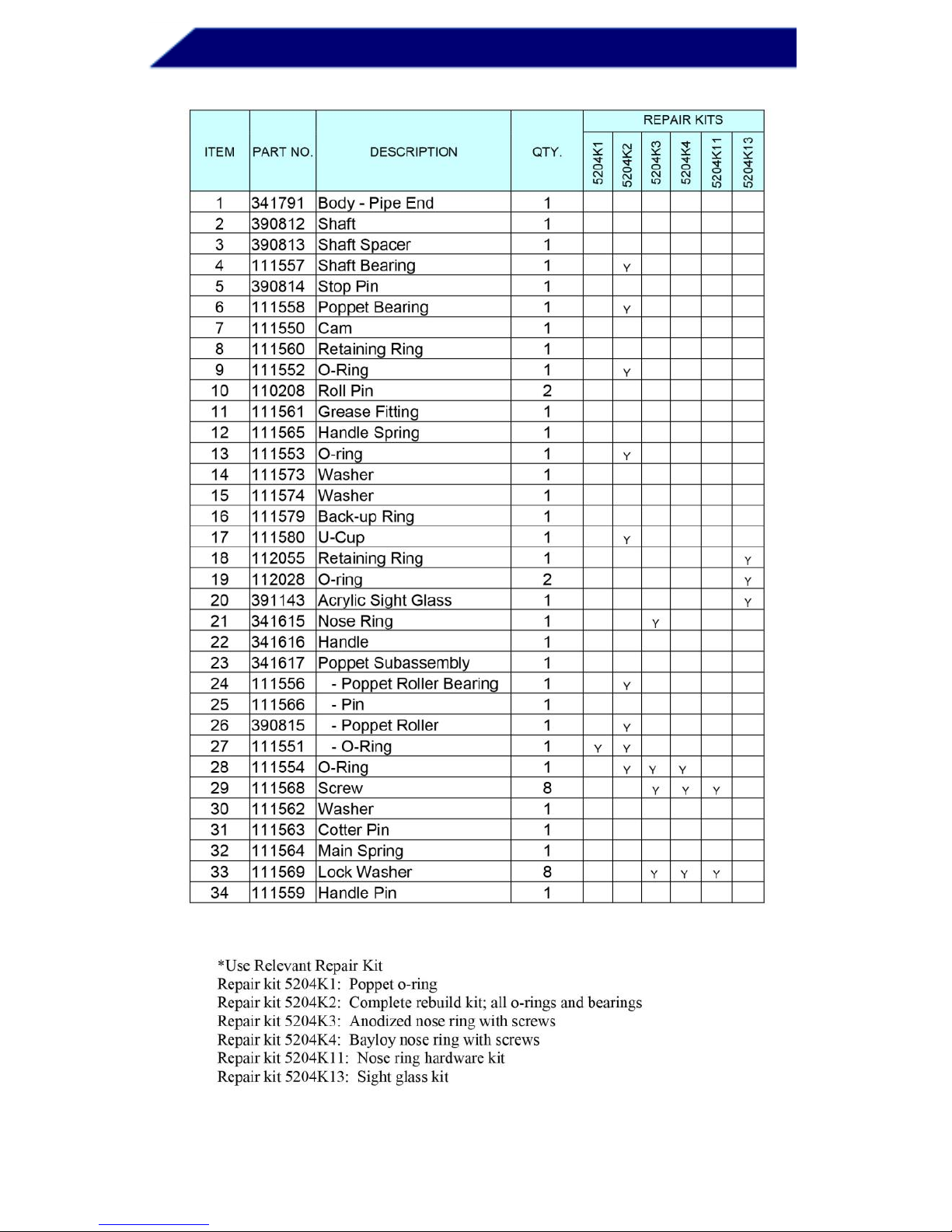
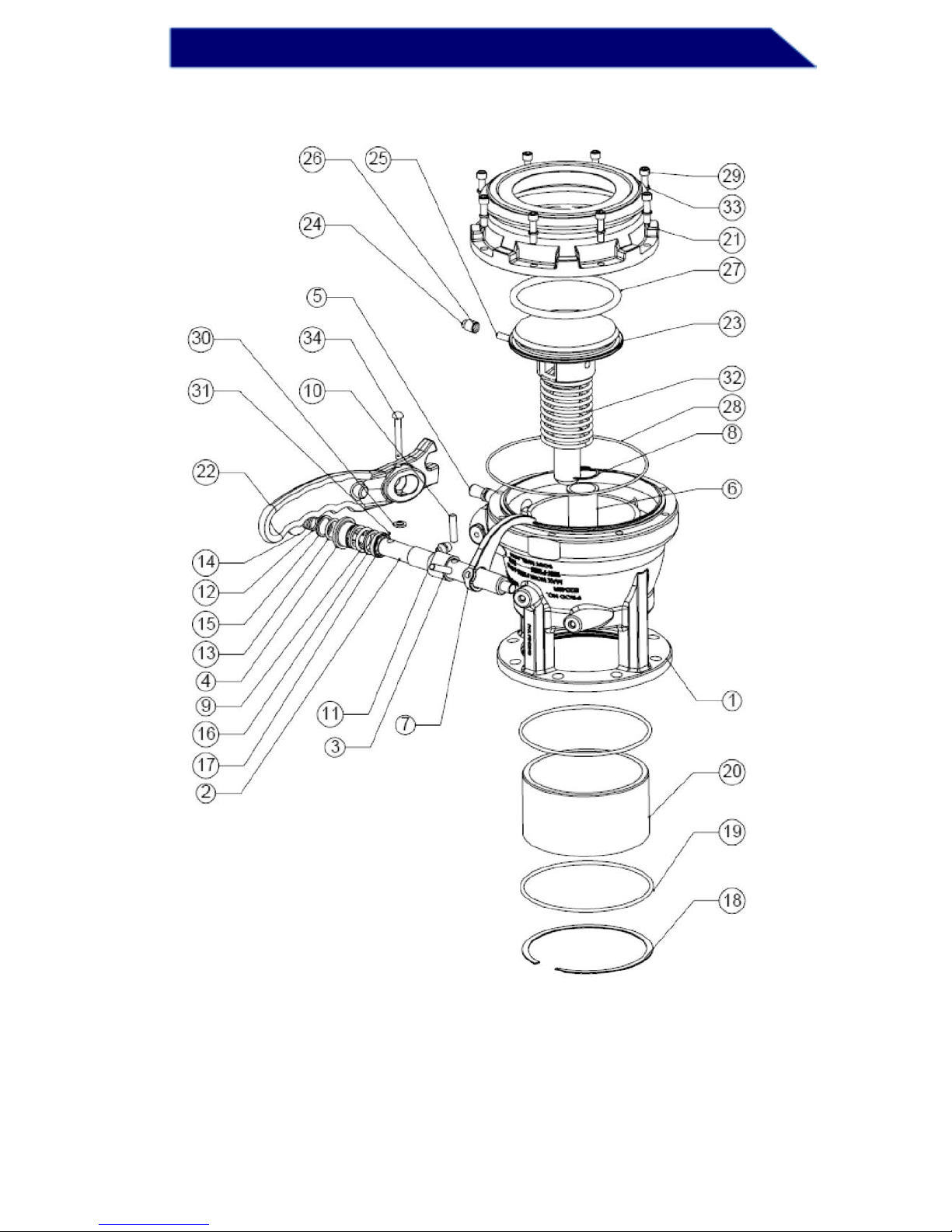
Parts are identified by the item number on the assembly drawing and
part list.
Maintenance and Part Replacement
Semi-Annual Inspection
Visual inspection of the valve operation can be done while the valve
is still attached to the tank. All safety precautions that apply to the
use of the valve must be followed and all the lines must be empty.
1. Visually examine 5204SFI API for worn or damaged parts, or any
other condition that may affect the operation of the valve.
2. Visually examine nose ring (21) for cavities, scratches, or other
deformation of the sealing surface.
3. Visually examine shaft (2) for significant dirt accumulation that
could cause shaft seal leakage.
4. Check that the handle (22) automatically positions at an angle to
the valve body (1) with detent end away from the stop pin (5).
5. Visually examine stop pin (5) for signs of wear and deformation.
When the handle is moved to open position, it should remain firmly
latched on the stop pin (5). If the handle cannot stay securely in the
latched open position due to stop pin (5) wear, stop pin (5) should be
replaced. Locking pliers can be used to unscrew the stop pin (5).
6. Visually examine the sight glass (20) for damage or sign of
leakage, check the sight glass for cracks. If the sight glass is cloudy,
the color of the sight glass changed, or visible cracks are seen, or
leakage can be found from the sight glass or the O-rings (19), replace
the sight glass. See the “REPLACEMENT OF SIGHT GLASS”
section for how to replace the sight glass.
7. To check the handle performance, open and close the API valve a
few times. The handle should move unobstructed and smoothly.
8. When released from the latched (or open) position, the poppet (23)
should instantly close and center.

5204SFI API Valves
5204SFI 090112 REV 3 5
9. Using a non-scratching tool, (piece of wood), push the poppet open
without using the operating handle. Push the poppet to the side and
make sure that the poppet reseats and centers itself when closed
slowly.
If any of the checks described above fails, additional maintenance is
required.
Yearly Inspection and Maintenance
The 5204SFI API can be disassembled and the seals may be
replaced while the valve is still attached to the trailer. The sight glass
(20) and O-rings (19) can only be replaced when the valve is
removed from the trailer. See the “REPLACEMENT OF SIGHT
GLASS” section for how to replace the sight glass.
It is recommended to draw a line (using a felt-tip pen) across the joint
between the pipe end (1) and the nose ring (21). The line is used
later in assembly to rotate the nose ring (21) from the starting
position, which helps balance out wear of the coupling surface.
Disassembly – Part I
THE POPPET IS HELD UNDER CONSIDERABLE SPRING
TENSION. WHENEVER THE NOSE RING (21) OR POPPET (23)
ARE REMOVED OR REASSEMBLED, THE VALVE MUST BE
LATCHED IN THE OPEN POSITION OR THE POPPET
OTHERWISE RESTRAINED (LOAD ONLY). PERSONAL
INJURIES MAY RESULT IF THIS PRECAUTION IS NOT TAKEN.
WHERE POLISHING IS INDICATED, USE NOT LESS THAN 600
GRIT POLISHING CLOTHS.
1. Inspect nose ring (21) for scratches on sealing surface. If there are
any scratches on the sealing surface, the nose ring (21) should be
replaced to avoid valve leakage. Faces without hard coating should
be polished around the bore and only in circumferential direction.
2. Poppet (23) should be inspected for scoring or raised metal on the
stem. Any raised metal on the poppet stem should be removed with
a fine flat file and polished in axial direction.
3. Inspect poppet bearing (6) for intrusion of any foreign material on
the inside diameter. Any foreign material on the inside diameter
should be carefully removed with a sharp tool and polished.

5204SFI API Valves
6 090112 REV 3 5204SFI
4. On completion of poppet (23) and poppet bearing (6) inspection,
test the bearing (6) on the poppet (23) without the spring (32) to
make sure that the bearing (6) smoothly slides along the poppet (23)
stem. If this is not the case, the bearing should be replaced.
5. Test rotation of the poppet roller (26) around the pin (25). If the
rotation is difficult, the roller bearing should be replaced. To access
the roller bearing, support the poppet (23) and release the pin (25)
using a ¼" pin punch.
6. Check the handle (22) for free and easy movement of the opening
and closing cycle. Operation of the handle (22) normally requires
limited effort. If operating the handle (22) involves stronger force, it
implies the need to clean and possibly replace the shaft bearing (4)
and the shaft (2).
7. Poppet O-ring (27) and main O-ring (28) should be inspected for
cracks, scratches, missing material, unusual hardness, softness,
roughness, and other signs of chemical damage. Do not remove
poppet O-ring from the poppet at this stage.
8. At this point it may be decided to replace the main O-ring (28) and
reassemble the valve if the first part of the inspection did not reveal
any damage or malfunction of the parts, or to continue with Part II of
disassembly and replace all the O-rings if there are any additional
concerns regarding the performance of the valve. Steps 5 through 8
of the Assembly section describe how to assemble the valve from this
point.
Disassembly – Part II
1. To remove two roll pins (10), turn the handle until the pin is
accessible and drive out each pin in turn using ¼" pin punch. If this is
done with the valve attached to the tank, take precautions to ensure
that the pins (10) do not enter upstream piping. To remove the cam
arm roll pin (10), ensure that the handle is rotated to a position such
that the roll pin will be clear of the deflector cone (valve body) as it is
driven out. If the roll pin appears not to drive further than
approximately ¼", check for contact between the roll pin and deflector
cone and slightly adjust the rotation of the handle to allow sufficient
clearance.
2. Take out handle (22) with shaft assembly, shaft spacer (3) and
cam (7).

5204SFI API Valves
5204SFI 090112 REV 3 7
3. Remove shaft bearing (4), O-ring (9), back-up ring (16) and u-cup
(17) from the pipe end (1) stuffing box.
4. Examine stuffing box area of the pipe end (1) for corrosion and, if
required, polish in circumferential direction.
5. To disassemble handle from shaft assembly, remove cotter pin
(31), washer (30), handle pin (34), washer (14), spring (12), washer
(15), and O-ring (13).
6. Polish sealing surfaces of the shaft (2) in a circumferential
direction. Remove any burrs that might have occurred during pin
punching. Carefully remove poppet O-ring (27) without damaging the
sealing surface of the poppet (23). Even the smallest scratches on
the O-ring groove will cause leakage.
Cleaning, Inspection and Replacement of
Disassembled Parts
Clean well and visually examine all the parts of the API. Remove any
burrs and sharp edges that could damage the seals during
reassembly. Replace any damaged parts.
Assembly
1. Before assembly, apply lubricant to the inside diameter of the pipe
end (1) stuffing box, to the u-cup (17), back-up ring (16), O-ring (9),
and shaft bearing (4). Insert u-cup (17) followed by back-up ring (16),
O-ring (9), and shaft bearing (4) inside pipe end (1) stuffing box.
2. Lubricate shaft (2) and install it through the bearing (4) into the
body (1) driving it through the shaft spacer (3) and the cam (7). Insert
pins (10) into the shaft holes.
3. Lubricate O-ring (13) and install it on the shaft (2). Continue
installing washer (15), spring (12), washer (14), and handle (22).
Insert handle pin (34). Position handle with detent end away from the
stop pin and then install washer (30) and cotter pin (31).
4. Liberally lubricate poppet O-ring (27) and install it on the poppet
(23) preventing torsion of the O-ring during assembly as it may cause
leakage. It is recommended to press on the full edge of the O-ring
(27) until it snaps around the poppet (27), and then push it into the Oring groove from opposite sides.

5204SFI API Valves
8 090112 REV 3 5204SFI
5. Install spring (32) and poppet (23) into the pipe end (1). Lead the
cam (7) over poppet roller (26) and latch the handle (22) in the open
position.
6. With lock washers (33) installed on each of the eight screws (29),
apply ‘never-seize’ on the screw threads.
7. Liberally grease O-ring (28) and install it on the nose ring (21). Use
the radial line drawn in the step 1 of disassembly and starting from
the initial alignment. Rotate the nose ring (21) one bolt hole
clockwise. Bolt screws with washers and ‘anti-seize’ applied to the
screw threads. Tighten using a crisscross flange torqueing sequence.
8. To ensure proper operation of the valve, repeat the steps of the
Semi-annual inspection.
Replacement of Sight Glass
Remove the 5204SFI API from the trailer. Remove the sight glass
(20) from the pipe end (1).
a.) Drill a through hole on the sight glass (20) as shown; make sure
not to damage any other parts. Apply penetrating oil to sight glass
(20) on outside and bottom end for easy removal.
b.) Use screw drivers or any round rod through the hole. Twist the
sight glass by the screw drivers or the rod to loosen the sight glass.
Make sure not to damage the pipe end.

5204SFI API Valves
5204SFI 090112 REV 3 9
c.) Remove the retaining ring (18) from the groove of the pipe end
(1). Push the sight glass out by the screw drivers or the rod. Make
sure not to damage the pipe end.
d.) Once the sight glass passes the inside O-ring, remove the screw
drivers or the rod. Continue to push the sight glass out from the
inside end by the screw drivers or the rod till the sight glass is out.
Make sure not to damage the pipe end.
Remove the O-rings (item 19, 2 pieces) from the grooves of the pipe
end (1). Clean all grooves and the inside of the pipe end (1) to
remove any debris and oil. Make sure not to scratch or damage the
grooves and inside of the pipe end.
Lubricate NEW O-rings (item 19, 2 pieces) and put them into the
grooves in the piped end (1).
Install the NEW sight glass (20) and make sure that the side with a
chamfer gets into the pipe end (1) first. Push the sight glass evenly
into the piped end till the side with a chamfer stops by the pipe end.
Use the old sight glass as a tool to push the new sight glass, if
necessary.
Install the NEW retaining ring (18) into the groove of the pipe end.

5204SFI API Valves
10 090112 REV 3 5204SFI
Handle Operating Positions
Maximum operating temperature is 140ºF. Do not clean the
sight glass by steam! Failure to follow the warning will void the
warranty.
Dixon Bayco Warranty
For complete warranty information, please refer to the latest
Dixon catalog.
 Loading...