

Dixon BAYCO 2180RK15, BAYCO 2180RK18A, BAYCO 2180RK18, BAYCO 2180RK15A, BAYCO 2182RK15 Maintenance & Operating Instructions
...Page 1
Maintenance & Operating Instructions
For Sales & Service Contact
For
BAYCO 2180 AIR RELIEF VALVE,
AUTHORIZED REPAIR CENTER REPAIR KIT
Part Numbers:
2180RK15…………15 (+2/-0) PSI Repair kit
2180RK18…………18 (+2/-0) PSI Repair kit
2180RK15A ………15 (+1/-1) PSI Repair kit
2180RK18A ………18 (+1/-1) PSI Repair kit
USA:
Dixon Bayco USA
Chestertown, Maryland
Phone: 410-778-2000
Fax: 410-778-4702
Toll Free: 800-355-1991
E-mail: dixonbayco@dixonvalve.com
www.dixonbayco.com
Mexico:
Dixva, S. de R.L. de C.V.
Monterrey, N.L
Phone: 01-800-00-DIXON (34966)
Fax: 01-81-8354-8197
E-mail: contactenos@dixonvalve.com.mx
www.dixonvalve.com
Asia Pacific:
Dixon (Asia Pacific) Pty Ltd
Wingfield, South Australia
Phone: +61 8 8202 6000
Fax: +61 8 8202 6099
E-mail: enquiries@dixonvalve.com.au
www.dixonvalve.com.au
Canada:
Dixon Group Canada Limited
Innisfil (Barrie), Ontario
Phone: 705-436-1125
Fax: 705-436-6251
Toll Free: 877-963-4966
E-mail: isales@dixongroupcanada.com
www.dixongroupcanada.com
Europe:
Dixon Group Europe Ltd
Preston, England
Phone: +44 (0)1772 323529
Fax: +44 (0)1772 314664
E-mail: enquiries@dixoneurope.co.uk
www.dixoneurope.co.uk
- 1 - 090088 R8
Page 2
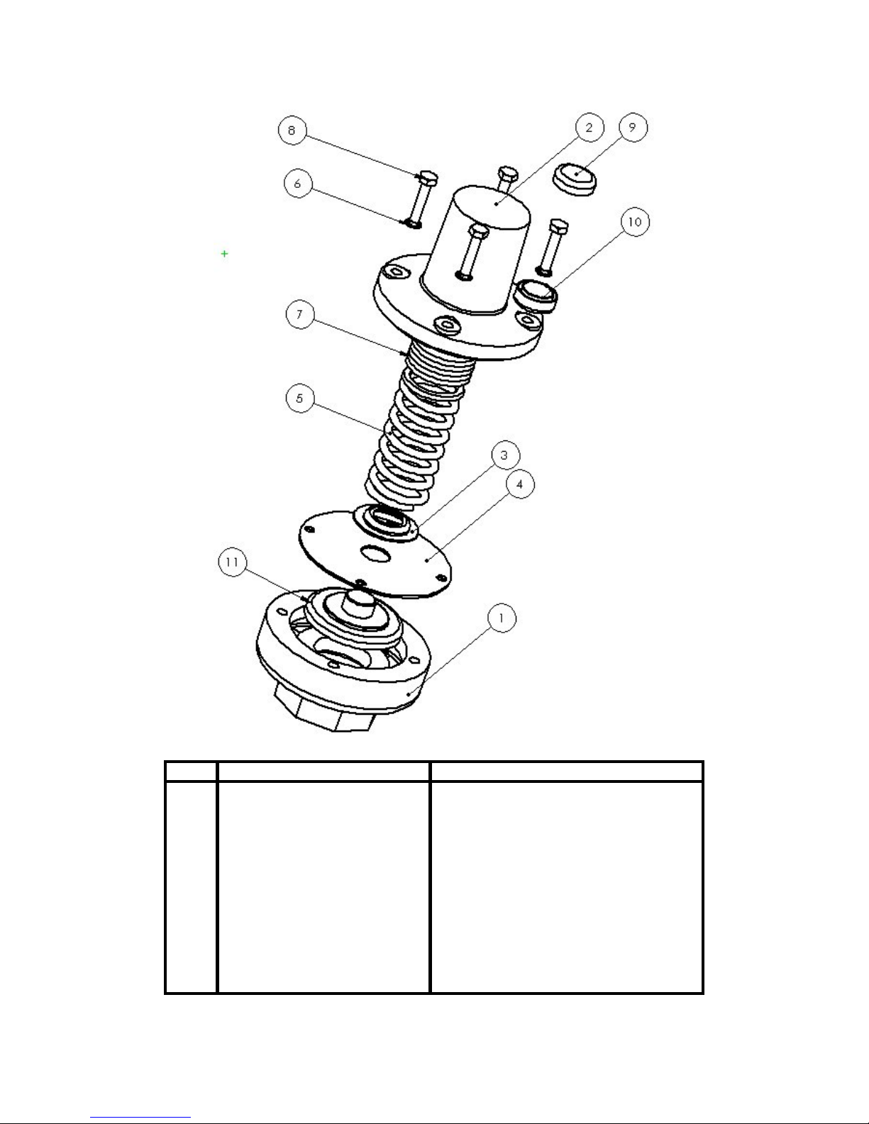
No.
DESCRIPTION
INCLUDED IN REPAIR KIT
1 VENT COWL NO
11
VALVE PLATE
YES
2 TOP COVER NO
3 SPRING SEAT YES
4 DIAPHRAGM YES
5 SPRING YES
6 WASHER YES (4)
7 SPACERS NO, DO NOT USE WITH THIS KIT
8 BOLT YES (4)
9 CUP SEAL UPPER HALF YES
10 CUP SEAL LOWER HALF YES
- 2 - 090088 R8
Page 3

IMPORTANT: To properly operate and maintain your Bayco 2180 air relief valve, the following
instructions are provided. Please read with care as improper handling or maintenance may cause a
hazardous condition. These instructions are intended for use with, and refer to, the 2180 air relief
valve with set pressures of 15psig and 18psig. These instructions, and the contents of this kit
should not be used with any other valve. Please ensure that you have the correct kit for your valve
and note that the 15psig spring and the 18psig spring are not interchangeable.
CAUTION: Do not modify your Bayco air relief valve in any manner other than as described in these
instructions. Failure to comply with these instructions including disassembly, tampering or
modifications using processes and parts not described in these instructions or supplied with
this will void the product warranty and could result in personal injury and extensive
property damage.
REPLACE AND REPORT: Immediately remove from service any air relief valve that is not performing
satisfactorily. Return & report the problem to your Dixon Bayco distributor for warranty
consideration.
Air Relief Valve Repair Procedure
DISASSEMBLY
IMPORTANT: Refer to the attached parts diagram throughout the following procedure.
Remove the air relief valve to a clean environment taking care not to damage the pipe thread during
removal.
Remove any residual surface contamination, dirt or debris from the external surfaces before proceeding
with disassembly.
WARNING: Bayco air relief valves are held together under considerable spring load. Ensure that the
vent cowl (1) and top cover (2) are restrained, using a vice or similar clamping device, before
attempting to undo the four bolts (8) securing the top cover (2) to the vent cowl (1). Ensure
that appropriate personal protective equipment, including eye protection, is worn
throughout. Failure to comply with these safety precautions may result in personal injury.
With the air relief valve clamped, as described above, break the existing tamper proof seal.
For leaded wire seals: Cut the wire, remove wire from bolt and discard.
For cup seals (as shown items 9 & 10): Carefully pry the cup seal away from the bolt using a flat
bladed screwdriver. Discard both cup seal halves.
With the air relief valve clamped, as described above, remove all four bolts (8) and washers (6).
When all bolts have been removed, the clamping arrangement holding the vent cowl to the top cover should
be slowly and carefully released.
Fully disassemble and lay out all of the components of the valve.
Carefully inspect all components for signs of damage or wear. Items 3-6 and 8-11 are contained in this
repair kit and must be replaced during rebuild.
- 3 - 090088 R8
Page 4

Clean the inside of the top cover (2) and vent Cowl (1) taking particular care to ensure that the valveseating surface on the vent cowl is free of surface contamination. Vent cowl seating surface must be clean
and smooth to create proper sealing surface, sanding with 200-400 grit sandpaper is recommended. Ensure
that all debris is removed from the interior of the top cover (2). Blow out as required, since, residual debris
may prevent the valve from operating correctly.
Layout the contents of the valve and replace Items 3-6 and 8-11 with the parts included in the kit.
IMPORTANT: Spacers (7) may be found in your existing valve. THESE SPACERS ARE TO BE
DISCARDED. This repair kit contains a spring, with either a +2–0psi, or +/-1psi tolerance
(dependant on kit purchased), that should provide the correct valve opening pressure without the
use of spacers. NO SPACERS ARE TO BE USED WITH THIS REPAIR KIT. Please note
that although the springs have been factory set to provide the required opening pressure, individual
variables related to specific valves and their applications might result in a rebuilt valve having an
opening pressure that falls outside of the expected tolerance band. In the event that the required
opening pressure (either 15psig or 18psig as noted on the kit) cannot be obtained through use of
the spring alone, ensure that you have the correct repair kit and contact your Dixon Bayco sales
representative immediately.
ASSEMBLY
Assemble the valve using the following procedure, referring to the diagram as needed.
Place vent cowl (1) on table with threaded portion lowermost.
Place valve plate (11) onto the seating surface of the vent cowl (1) ensuring that the flat sealing surface is
facing down (as shown in diagram) and in contact with the vent cowl seating surface.
Next place the diaphragm (4) onto the valve plate (11) so that the center hole of the diaphragm is aligned
with the stem of the valve plate and the four cutouts on the outer edge of the diaphragm are aligned with the
threaded holes in the vent cowl (1).
Place the spring seat (3) on to the diaphragm (4) and the stem of the valve plate (11).
Place spring (5) onto the stem of the valve plate (11) and on top of the spring seat (3).
Place top cover (2) onto the top of the spring and, using a suitable clamping device, bring the top cover and
vent cowl (1) together, ensuring that the diaphragm (4) is still aligned with the threaded holes on the vent
cowl. Check to ensure that the through holes in the top cover are also aligned with the threaded holes in the
vent cowl.
When the valve assembly is satisfactorily clamped together, take the bottom half of the tamper proof cup
seal (10) and place it on the top cover flange (2) so that the hole in the cup seal is aligned with one of the
holes in the top cover flange.
Place a washer (6) on each of the four bolts (8) and thread each bolt in turn into the valve assembly, as
shown. Ensure that one of the bolts passes through the tamper proof cup seal lower half (10) as described
in the step above.
Place the upper half of the tamper proof cup seal (9) onto the assembled lower half (10) and press firmly to
snap the two halves together.
When all four bolts have been securely fastened, the valve assembly may be unclamped and is now ready
for testing.
- 4 - 090088 R8
Page 5

AIR RELIEF VALVE – THEORY OF OPERATION
All Bayco air relief valves are spring-loaded system-pressure actuated devices consisting of a valve disc
held in a closed position against a valve seat by means of spring pressure. The pressure in the system to be
protected always acts on the valve disc and would tend to open the valve, however the spring load is set so
as to ensure that the pressure in the system, at normal operating pressures, is insufficient to open the valve.
However, when the system pressure builds to a level when the pressure load on the valve disc is equal to
the load exerted by the spring, the valve will begin to open. If the pressure in the system were to be held at
this level, the load acting to open the valve and the spring load acting to keep the valve closed would
remain in equilibrium and the valve would be neither open nor closed. In such circumstances the valve will
tend to flutter on the valve seat and may release a small amount of air but will not be relieving significant
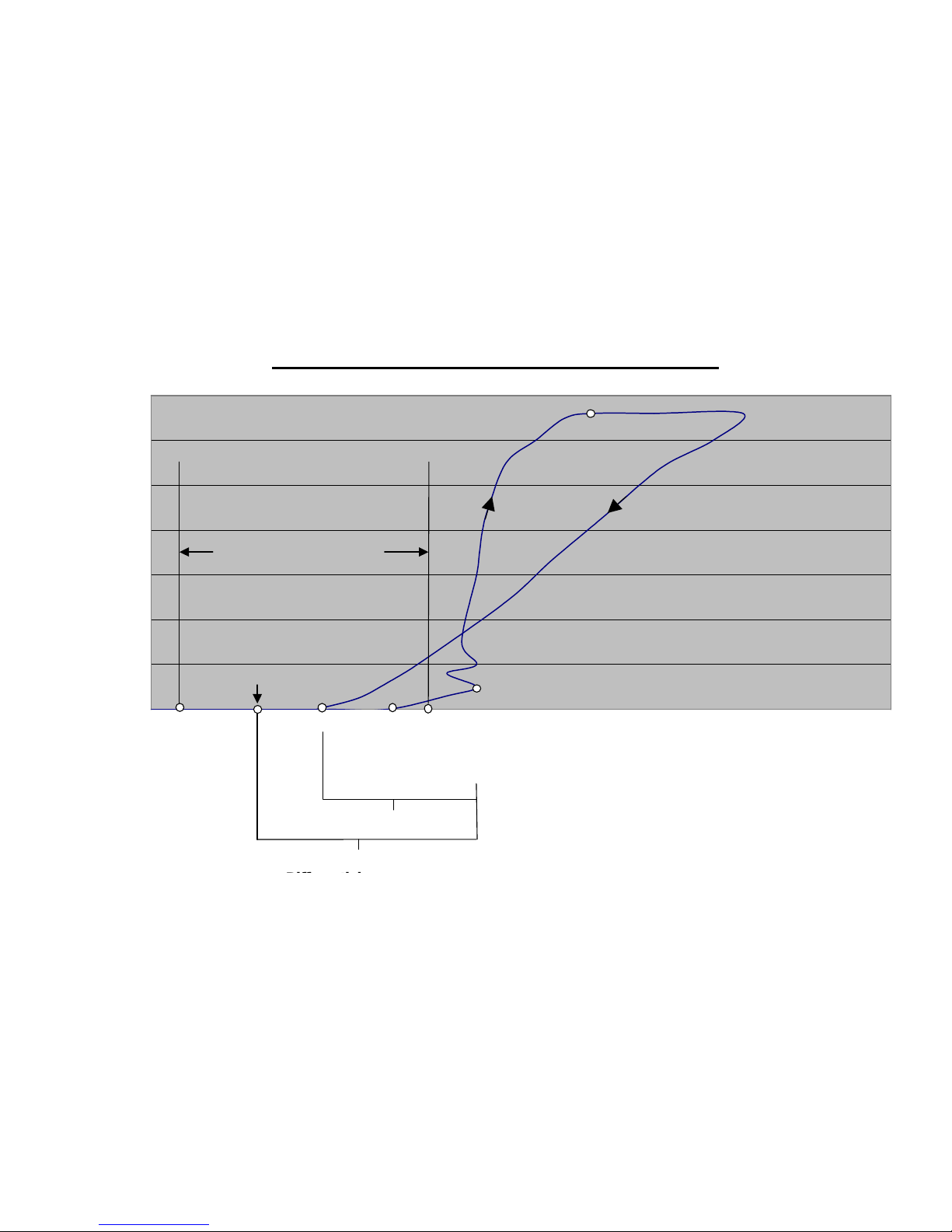
pressure from the system. This point is known as the Warning Pressure or Cracking Pressure.
If the pressure in the system continues to rise, the load acting on the face of the valve, and tending to open
the valve will also continue to rise and will begin to exceed the load exerted by the spring, which tends to
keep the valve closed. When the opening load, due to system pressure, exceeds the closing load, due to
spring force, the valve will open, and, as long as the system pressure remains sufficient, will stay open.
This point is known as the Opening Pressure or Set Pressure (also referred to as Rated or Popping
Pressure). The difference between the Crack Pressure and Opening Pressure varies between valves and is
also related to the system flow rate. However the two should not be confused, as there is a significant
difference in pressure between the two points.
If the system pressure continues to rise, the valve will continue to open and will relieve more and more air
until the valve is fully open. At this point the valve will be relieving close to its maximum airflow rate,
further increase in system pressure will show only relatively minor increases in flow rate. If the system
pressure decreases the relieving airflow rate will reduce and the valve will start to close but will not fully
reseat until some pressure below the Opening Pressure, this pressure is known as the Reseating Pressure
and the difference between the two pressures is known as “Blowdown”.
In practice the valve should be matched to the system to be protected such that the maximum airflow rate of
the valve is never utilized, i.e. the valve should be capable of relieving a sufficient volume flow rate of air
at the opening pressure to ensure that the system pressure drops significantly. If the valve is open and the
system pressure continues to rise above the opening pressure then the valve is relieving less air than is
being put into the system. This is a potentially dangerous situation that may lead to over pressurization. Air
relief valves should always be matched to the system to be protected such that the relieving airflow rate of
the valve at the maximum allowable system pressure, and ideally at the Opening Pressure, is well in excess
of the system input flow rate at that same pressure.
- 5 - 090088 R8
Page 6
- 6 - 090088 R8
Pressure and Vacuum Relief Valve Terminology
Pressure
Flow Rate
Opening
"Set"
"Rated"
"Popping"
Warning
"Hissing"
"Cracking"
Reseating Fully Open
Blowdown
Seating Pressure
Nominal System Pressure
Typical System
Pressure Range
Page 7

TESTING
IMPORTANT: The opening pressure of this valve may indicate differently depending on the test
equipment, instrumentation and air supply used. Where possible the valve should be tested using
identical conditions and the same equipment as will be found on the system to be protected. When
this is not practical the test set-up should, as closely as possible, approximate the conditions of the
system to be protected. Additionally the calibration of your test system should be checked against
your actual system by comparing the opening pressure of the same relief valve on both systems.
IMPORTANT: Ensure that your air supply is rated to at least 100psi and that at least 250SCFM of airflow
is available. If the air supply flow rate is much less than the rated flow rate of the relief valve, the
relief valve will appear to relieve at a lower pressure than the rated value. This discrepancy arises
because the relief valve is a spring device that is designed to lift slightly before the set relief
(opening) pressure, but will not flow a significant volume of air until the air reaches the opening
pressure. If the SCFM flow rate is low the air relief valve will relieve a volume of air at lift
pressure that cannot be made up by the supply source, therefore the tester will not be able to reach
the opening pressure setting. In this situation the maximum pressure read on the tester pressure
gauge will be the initial lift pressure and not the rated opening pressure.
WARNING: All test equipment should be rated suitable for use with high-pressure air.
Ensure that all supply lines and connections are at least ¾”.
Ensure that all relevant instrumentation is correctly calibrated.
The most accurate results will be obtained when the relief valve to be tested is connected to an accumulator
or air receiver tank such that the dynamic affect of the compressor system is reduced. Failure to do so may
result in an indicated opening pressure lower than the actual.
Screw the pressure relief valve to be tested into a 2” port on your test system using pipe sealant on the air
relief valve threads.
Open supply pressure isolation valve and allow air receiver tank pressure to rise.
IMPORTANT: Tank pressure should be allowed to rise at a rate of approximately 2psi / second. Flow
rates greater than this will cause the relief valve to flutter rapidly. In this condition the valve plate
inertia may cause the apparent opening pressure to be lower than the calibrated value and will
make accurate testing impossible.
IMPORTANT: The relief valve will start to discharge at a pressure slightly below the rated value, at this
pressure some hissing may be evident but the pressure in the tank should continue to rise
(assuming air source provides a sufficient flow rate). The valve opening pressure (RATED
VALUE) can be read on the tester pressure gauge when the valve plate (11) reaches an
equilibrium (open) position.
WARNING: If the air supply provides a flow rate in excess of the maximum flow rate capacity of the
relief valve at the relieving pressure, the valve will not be able to relieve a sufficient volume
of air to prevent tank pressure from continuing to rise. In this condition serious personal
injury and extensive property damage may occur due to over pressurization of test
components.
- 7 - 090088 R8
Page 8

VALVE INSTALLATION
Prior to installation, clean any dirt or foreign matter from threading surfaces.
Install Air Relief Valve in positions ranging from vertical (0 deg.) to horizontal (90 deg). Do not install
valve in inverted position.
Install Air Relief Valve with exhaust area positioned so exhaust vents safely (preferably down as shown in
attached diagram). In horizontal applications, ensure that the small vent hole in the side of the top cover is
facing downward. Downward venting helps prevent dirt or debris from entering the valve.
Apply pipe sealant to threading surfaces prior to installation.
Thread the valve into place by hand and tighten using a crescent wrench (or equivalent) across the hex flats.
CARE AND HANDLING
Brand New Bayco air relief valves are tested at the factory and are in proper working condition when
shipped. Air Relief valves are designed to be tough and to provide long service with reasonable care and
handling.
OPERATION AND MAINTENANCE
INSTRUCTIONS
Weekly visual inspection of the valve is recommended.
Ensure that the valve body and exhaust vents are kept clear of build up.
Ensure that exhaust vents remain clear of all obstructions.
Inspect the valve regularly to ensure thread tightness. Excessive vibration may cause valve to loosen over
time.
The Factory produced Bayco Air Relief Valve is assembled with tamper resistant screws and is pre-set at
the factory to customer requirements. Any attempt to disassemble or adjust settings for any reason will
void the manufacturer’s warranty. See warranty section below for warranty details related to the use of this.
Should any problems arise with the valve, remove from service immediately and contact your Dixon Bayco
distributor.
DIXON BAYCO WARRANTY
For warranty information, please refer to the inside back cover of the latest Dixon catalogue.
- 8 - 090088 R8
Page 9

Entretien & Mode d’emploi
Pour vente et service contactez
pour
SOUPAPE DE CONTRÔLE DE PRESSION BAYCO 2180,
TROUSSE DE RÉPARATION AUTORISÉE
Numéro des pièces:
2180RK15………. Trousse de réparation 15 (+2/-0) PSI
2180RK18………. Trousse de réparation 18 (+2/-0) PSI
2180RK15A ……. Trousse de réparation 15 (+1/-1) PSI
2180RK18A ……. Trousse de réparation 18 (+1/-1) PSI
E-U:
Dixon Bayco USA
Chestertown, Maryland
Téléphone: 410-778-2000
Fax: 410-778-4702
Sans frais: 800-355-1991
E-mail: dixonbayco@dixonvalve.com
www.dixonbayco.com
Mexique:
Dixva, S. de R.L. de C.V.
Monterrey, N.L
Téléphone: 01-800-00-DIXON (34966)
Fax: 01-81-8354-8197
E-mail: contactenos@dixonvalve.com.mx
www.dixonvalve.com
Asie et Pacifique:
Dixon (Asia Pacific) Pty Ltd
Wingfield, South Australia
Téléphone: +61 8 8202 6000
Fax: +61 8 8202 6099
E-mail: enquiries@dixonvalve.com.au
www.dixonvalve.com.au
Canada:
Dixon Group Canada Limited
Innisfil (Barrie), Ontario
Téléphone: 705-436-1125
Fax: 705-436-6251
Sans frais: 877-963-4966
E-mail: isales@dixongroupcanada.com
www.dixongroupcanada.com
Europe:
Dixon Group Europe Ltd
Preston, England
Téléphone: +44 (0)1772 323529
Fax: +44 (0)1772 314664
E-mail: enquiries@dixoneurope.co.uk
www.dixoneurope.co.uk
- 1 - 090088(fr) R8
Page 10

- 2 - 090088(fr) R8
Page 11

IMPORTANT: Pour un bon fonctionnement et pour bien entretenir votre soupape de contrôle de pression
Bayco 2180, les instructions suivantes sont fournies. S’il vous plait lire avec soin, une
manipulation incorrecte ou un mauvais entretien peut provoquer une situation dangereuse. Ces
instructions sont en place pour l’usage d’une soupape de contrôle de pression 2180 avec une
pression préréglée de 15psig et 18psig. Ces instructions et le contenu de cette trousse ne doivent
pas être utilisés avec aucunes autres soupapes. S’il vous plait assurez-vous d’avoir la bonne
trousse de réparation et assurez-vous que la soupape de 15psig soit avec un ressort de 15psi et que
la soupape de 18psig soit avec un ressort de 18psi.
ATTENTION : Ne modifiez pas vos soupapes de contrôle de pression d’aucunes autres façons
qu’indiquées dans ces instructions. Si vous ne suivez pas ces conditions, le démontage,
l’altération et la modification faites de façon différente que celles indiqués ou l’usage des
pièces différente que les notre annulera la garantie du produit et pourrait causer des
accidents ou endommager vos propriétés.
REMPLACEZ ET INFORMEZ : Mettez les soupapes de contrôle de pression qui ne fonctionnent pas
de façon satisfaisante hors services immédiatement. Retournez-les et informez votre
distributeur Dixon pour la garantie
Procédures de réparation pour les soupapes de contrôle de
pression
DÉMONTAGE
IMPORTANT: Consultez le diagramme fourni pour les procédures suivantes.
Retirez et placez la soupape de contrôle de pression dans un environnent propre en vous assurant de ne pas
endommager les filets du tuyau.
Retirez toute la saleté et les débris de la surface extérieure avant de continuer le démontage.
AVERTISSEMENT : Les soupapes de contrôle de pression Bayco sont retenues ensemble par une
tension considérable d’un ressort. Assurez- vous que la partie inférieure (1) et le couvercle
supérieur (2) soient restreint avec un étau ou un outil semblable avant de défaire les quatre
boulons qui sécurisent le couvercle supérieur (2) en place à la partie inférieure (1). Assurezvous de porter des équipements appropriés pour votre protection, incluant une protection
pour vos yeux. Si vous ne suivez pas ces précautions un accident pourrait en résulter.
Avec la soupape de contrôle de pression en place dans un étau et brisez le scellé “anti-altération”.
Pour les scellés de plomb : Coupez le fil, retirez le fil des boulons et jetez-le.
Pour les scellés “anti-altération” (indiquer par les pièces 9 & 10) : Retirez le sceau du couvercle
des boulons en utilisant un tournevis à tête plate. Jetez les deux moitiés du sceau.
Avec la soupape de contrôle de pression en place dans un étau, retirez les quatre boulons (8) et les
rondelles (6)
Lorsque tous les boulons sont retirés, l’étau retenant la partie inférieure à la partie supérieur devrait être
relâché lentement.
Démontez la soupape complètement et étalez tous les composants.
Inspectez soigneusement toutes les parties pour l’usure et les dommages. Les pièces 3-6 et 8-11 sont
incluses dans la trousse de réparation et doivent être remplacé durant le remontage.
- 3 - 090088(fr) R8
Page 12

Nettoyez l’intérieur du couvercle supérieur (2) et la partie inférieure (évent du capot) (1), portez une
attention particulière au siège de la partie inferieure et assurez-vous qu’’il n’y a aucune obstructions. Le
siège de la partie inférieure doit être propre et lisse afin d’assurer une bonne étanchéité, sablez la surface
avec du papier sablé de 200-400 grains. Assurez- vous que tous les débris soient retirés de l’intérieur du
couvercle supérieur (2). Nettoyez-le correctement car des débris résiduels pourraient empêcher la soupape
de fonctionner correctement.
Étalez tous les composants de la soupape et remplacez les pièces 3-6 et 8-11 avec les pièces inclues dans la
trousse.
IMPORTANT : Vous pourrez trouver des entretoises (7) dans votre soupape en main. VOUS DEVEZ
JETER CES ENTRETOISES. Cette trousse de réparation contient un ressort avec une tolérance
de +2-0psi ou +/- 1 (dépendent de quelle trousse que vous avez achetée), cela devrait vous donner
une bonne pression d’ouverture sans avoir recourt à des entretoise. CES ENTRETOISES NE
DOIVENT PAS ÊTRE UTILISÉES AVEC CETTE TROUSSE DE RÉPARATION. S’il
vous plait notez que même si les ressorts ont été choisis à la manufacture pour fournir la bonne
pression d’ouverture, les variables individuelles liées aux soupapes et leurs applications
spécifiques peuvent causer l’ouverture d’une soupape reconstruite d’avoir une pression élevée ou
abaissée que celle attendue. Si la pression d’ouverture (soi 15 psig ou 18 psig tel que noté sur la
trousse) que vous voulez n’est pas atteinte avec l’usage du ressort seulement, assurez-vous
d’avoir la bonne trousse de réparation et contactez votre représentant Dixon immédiatement
ASSEMBLEMENT
Assemblez la soupape en utilisant les procédures suivantes, en faisant référence au diagramme si
nécessaire.
Placez la partie inférieure (1) sur une table.
Placez le clapet (11) sur le siège de la partie inférieure (évent du capot) (1) assurez-vous que la surface de
l’étanchéité de caoutchouc soit en contact avec le siège de la partie inférieure.
Ensuite placez le diaphragme (4) sur le clapet (11) de façon que le trou central du diaphragme soit aligné
avec la tige du clapet et que les quatre embouchures sur le bord du diaphragme soient alignées avec les
trous filetés de la partie inférieure.
Placez le siège du ressort (3) sur le diaphragme (4) et sur la tige du clapet (11)
Placez le ressort (5) sur la tige du clapet et sur le siège du ressort (3)
Placez le couvercle supérieur (2) sur le ressort et en utilisant un étau, amener le couvercle supérieur et la
partie inférieure (évent du capot) (1) ensemble en vous assurant que le diaphragme (4) soit aligné avec les
trous filetés de la partie inférieure. Assurez-vous aussi que les trous du couvercle supérieur soient alignés
avec les trous filetés de la partie inférieure (évent du capot).
Lorsque vous avez assemblez votre soupape de façon satisfaisante, prenez la partie inférieure (évent du
capot) du scellé “anti-altération” (10) et placez-le sur le couvercle supérieur (2) de façon que le trou du
scellé “anti-altération” soit aligné avec les trous du couvercle supérieur
Placez une rondelle (6) sur chacun des quatre boulons (8) et vissez chaque boulon dans l’assemblée de la
soupape, comme le dessin le montre. Assurez-vous qu’un boulon passe à travers la partie inférieure du
scellé “anti-altération” (10) comme indiqué à l’étape ci-dessus.
Placez la partie supérieure du scellé “anti-altération” (9) sur la partie inférieure (10) et appuyez fermement
afin d’enclencher les deux parties ensembles.
- 4 - 090088(fr) R8
Page 13

Lorsque les quatre boulons sont sécurisés correctement, l’assemblée de la soupape peu être retiré de l’étau
et est prête à être testée.
- 5 - 090088(fr) R8
Page 14

SOUPAPES DE CONTRÔLE DE PRESSION –
PRINCIPE DE FONCTIONNEMENT
1. Toutes les soupapes de contrôle de pression Bayco sont actionnées par moyen de tension à ressort
et sont composées d’un disque à soupape, retenu en position fermé contre le siège de la soupape en utilisant
la pression d’un ressort. Afin de protéger la pression d’air dans le système, la pression d’air pèse toujours
sur le siège de la soupape et aurait tendance à ouvrir la soupape, cependant la tension du ressort est ajustée
pour que la pression du système normale soit insuffisante pour ouvrir la soupape. Toutefois, lorsque la
pression du système est à un niveau où la pression sur le siège de la soupape est égale à la pression exercée
par le ressort, la soupape s’ouvrira. Si la pression dans le système est maintenue à ce niveau, la force
exercée pour ouvrir la soupape & la force exercée par le ressort pour garder la soupape fermée sera en
équilibre, et la soupape sera ni fermée ni ouverte. Dans de telles circonstances, la soupape aura une
tendance à produire des battements et libérer une petite quantité d’air mais elle ne relâchera pas une
pression signifiante dans le système. Ce point est connu comme La Pression d’Avertissement ou La
Pression d’Ouverture.
Si la pression du système continu à augmenter, la pression contre le disque de la soupape augmentera et
surpassera la force du ressort qui tien la soupape fermée. La soupape restera ouverte tant que la pression du
système pour ouvrir la soupape sera plus élevée que la tension du ressort. Ce point est connu sous les noms
pression de pleine décharge ou pression de tarage. La différence entre la pression d’ouverture et la pression
plaine décharge varie selon les soupapes et dépend aussi du débit pneumatique du système. Cependant ne
confondez pas les deux car il y a une différence de pression signifiante entre les deux points
Si la pression du système continue à augmenter, la soupape va continuer à s’ouvrir et relâchera de plus en
plus d’air jusqu'à ce qu’elle soit complètement ouverte. À ce point ci la soupape relâchera près de son débit
d’air maximal, une augmentation additionnelle de la pression aura un effet relativement mineur à ce qui
concerne la hausse du débit d’air. Si la pression du système diminue, le relâchement du débit d’air
diminuera et la soupape commencera à se fermer, mais le disque de la soupape ne se repositionnera pas
complètement jusqu'à ce que la pression diminue plus bas que la Pression de Pleine Décharge, cette
pression est connue comme La Pression de Fermeture et la différence entre les deux est connue sous le nom
« une Purge Rapide ».
La soupape de contrôle de pression devrait avoir un débit d’air supérieur à celui du système du souffleur,
ex : si le souffleur produit 600 SCFM le débit d’air de la soupape de contrôle devrait être supérieur comme
à 700 SFCM. Si la soupape est ouverte et la pression du système continue à augmenter plus que la pression
d’ouverture, cela veut dire que la soupape relâche moins d’air qu’elle en prend. Il pourrait en résulter une
situation dangereuse qui pourrait causer une surpression.
- 6 - 090088(fr) R8
Page 15

- 7 - 090088(fr) R8
Page 16

ESSAI
IMPORTANT : La pression d’ouverture de cette soupape peut être indiquée différemment dépendant de
l’équipement d’analyse, l’instrumentation et la source d’air. Si c’est possible la soupape devrait
être analysé de la même façon et avec les même équipements que le système qui demande une
protection. Si ce n’est pas pratique l’installation d’essai devrait ressembler au plus possible au
système qui devrait être protégé. En addition, l’étalonnage votre système devrait être vérifié en
comparaison votre système actuel en vous assurant que la pression d’ouverture de la soupape est la
pour les deux systèmes.
IMPORTANT : Assurez-vous que votre pression d’air soit au moins à 100psi et que le débit d’air
disponible soit au moins à 250 SCFM. Si l’alimentation d’air est beaucoup moins que le taux de
débit de la soupape, la soupape apparaitra de se relâcher à un taux de pression moins qu’au taux de
réglage. Cette contradiction arrive parce que la soupape de pression est un ressort qui est conçu
pour se soulever légèrement pour relâcher (en s’ouvrant) la pression d’air, mais ne relâchera pas
un débit d’air signifiant jusqu'à ce que l’air atteigne la pression d’ouverture. Si le débit SCFM
(volume) est bas, la soupape de contrôle de pression va relâcher un volume d’air à une pression
pour lever le disque de la soupape que la source d’air ne sera pas capable de remplacer. Comme
résultat votre banc d’essai ne sera pas capable obtenir la pression de réglage. Dans cette situation,
la pression maximale tel que indiquée sur le manomètre sur votre banc d’essai sera la pression
pour lever le disque de la soupape & non la pression réglée de pleine décharge.
AVERTISSEMENT: Tous les équipements d’essai devraient être ajustés pour l’usage d’une pression d’air
élevée.
Assurez-vous que toutes les lignes d’alimentations et les connexions soient au moins ¾’’.
Assurez-vous que toutes les instrumentations importantes soient étalonnées correctement.
Les résultats les plus précis seront obtenus lorsque la soupape de contrôle qui doit être analysé soit
connectée à un accumulateur ou un réservoir d’air de façon que la dynamique du compresseur soit réduite.
Si vous ne le faite pas une indication de la pression d’ouverture pourrait en résulter même si la pression
actuelle est plus basse.
Vissez la soupape de contrôle qui doit être analysé à une connexion de 2” sur votre système d’essai en
utilisant un produit d’étanchéité à raccords sur les filets de la soupape de contrôle.
Ouvrez la soupape d’alimentation et d’isolement de la pression et permettez la pression de l’air du
réservoir d’air d’augmenter.
IMPORTANT : La pression du réservoir devrait augmenter à un taux approximatif de 2psi / seconde. Un
débit supérieur à cela causera les battements rapides de la soupape de contrôle. Dans ce cas,
l’inertie de la plaque de la soupape peut causer à la pression de pleine décharge à être plus basse
que la valeur étalonnée et rendra une analyse précise impossible.
IMPORTANT : La soupape de contrôle commencera à se décharger à une pression légèrement plus basse
que la valeur étalonné, à cette pression vous pourrez entendre des sifflements, mais la pression du
réservoir devrait continuer à augmenter (assumant que la source d’air produise un débit d’air
suffisant).
.
AVERTISSEMENT : Si l’alimentation d’air fourni un débit d’air supérieur à la capacité d’air que la
soupape de contrôle peut supporter, la soupape ne sera pas capable de relâcher un volume
d’air suffisant pour empêcher la pression d’air du réservoir d’augmenter. Dans ce cas, un
accident sérieux ou des dommages couteux pourrait arriver causé par une surpression des
équipements du banc d’essai.
- 8 - 090088(fr) R8
Page 17

INSTALLATION DE LA SOUPAPE
Avant l’installation, nettoyez toute la saleté ou les débris des surfaces filetés.
Installez la soupape de contrôle de pression dans une position allant de la verticale (0º) jusqu'à l’horizontale
(90º). N’installez pas la soupape en position inversée.
Installez la soupape de contrôle de pression dans une position ou l’air s’échappera de façon sécuritaire
(préférablement vers le bas). Durant l’application horizontale, assurez vous que le petit trou sur le coté de la
pièce pointe vers le bas. La ventilation vers le bas aide à empêcher la saleté ou les débris de pénétrer la
soupape.
Appliquez un produit d’étanchéité à raccords sur les filets avant l’installation.
Vissez la soupape en place à la main et serrer la avec une clé a molette (ou semblable) sur la partie
hexagone de la pièce.
SOIN ET ENTRETIEN
Les nouvelles soupapes de contrôle de pression Bayco sont testées à la manufacture et sont en bonnes
conditions lorsqu’elles sont expédiées. Les soupapes de contrôle de pression sont conçues pour être
résistantes et offrir un long service si on en prend soin et les traitent raisonnablement.
OPERATION ET INSTRUCTIONS D’ENTRETIENS
Une inspection visuelle hebdomadaire de la soupape est recommandée.
Assurez-vous que la soupape et la voie d’échappement soient claires de toute accumulation.
Assurez-vous que la voie d’échappement soit libre de toute obstruction.
Inspectez la soupape régulièrement pour vous assuré qu’elle soit serrée. La vibration excessive peut causer
la soupape de se desserrer avec le temps.
La manufacture Dixon produit des soupapes de contrôle de pression assemblée avec des vis “anti-
altération” et préréglée à la manufacture aux besoins du client. Toute tentative de désassembler ou
d’ajuster les réglages annuleront la garantie du manufacturier. Regardez la section ci-dessous pour plus de
détails sur la garantie.
Si vous avez n’importe quel problème avec cette soupape, retirez la du service immédiatement et contactez
votre distributeur Dixon.
GARANTIE DIXON
Pour plus d’informations complètes sur la garantie, s’il vous plait se référer à la
couverture intérieure de la dernière page du dernier catalogue Dixon.
- 9 - 090088(fr) R8
 Loading...