

Page 1
Installation & Operating
Instructions
For
BAYCO ELBOW EXTENSION KITS
Part Numbers
6000EXT & 6400EXT
Canada:
Dixon Group Canada Limited
Innisfil (Barrie), Ontario
Phone: 705-436-1125
Fax: 705-436-6251
Toll Free: 877-963-4966
E-mail: isales@dixongroupcanada.com
www.dixongroupcanada.com
Europe:
Dixon Group Europe Ltd
Preston, England
Phone: +44 (0)1772 323529
Fax: +44 (0)1772 314664
E-mail: enquiries@dixoneurope.co.uk
www.dixoneurope.co.uk
USA:
Dixon Bayco USA
Chestertown, Maryland
Phone: 410-778-2000
Fax: 410-778-4702
Toll Free: 800-355-1991
E-mail: dixonbayco@dixonvalve.com
www.dixonbayco.com
Mexico:
Dixva, S. de R.L. de C.V.
Monterrey, N.L
Phone: 01-800-00-DIXON (34966)
Fax: 01-81-8354-8197
E-mail: contactenos@dixonvalve.com.mx
www.dixonvalve.com
Asia Pacific:
Dixon (Asia Pacific) Pty Ltd
Wingfield, South Australia
Phone: +61 8 8202 6000
Fax: +61 8 8202 6099
E-mail: enquiries@dixonvalve.com.au
www.dixonvalve.com.au
For Sales & Service Contact
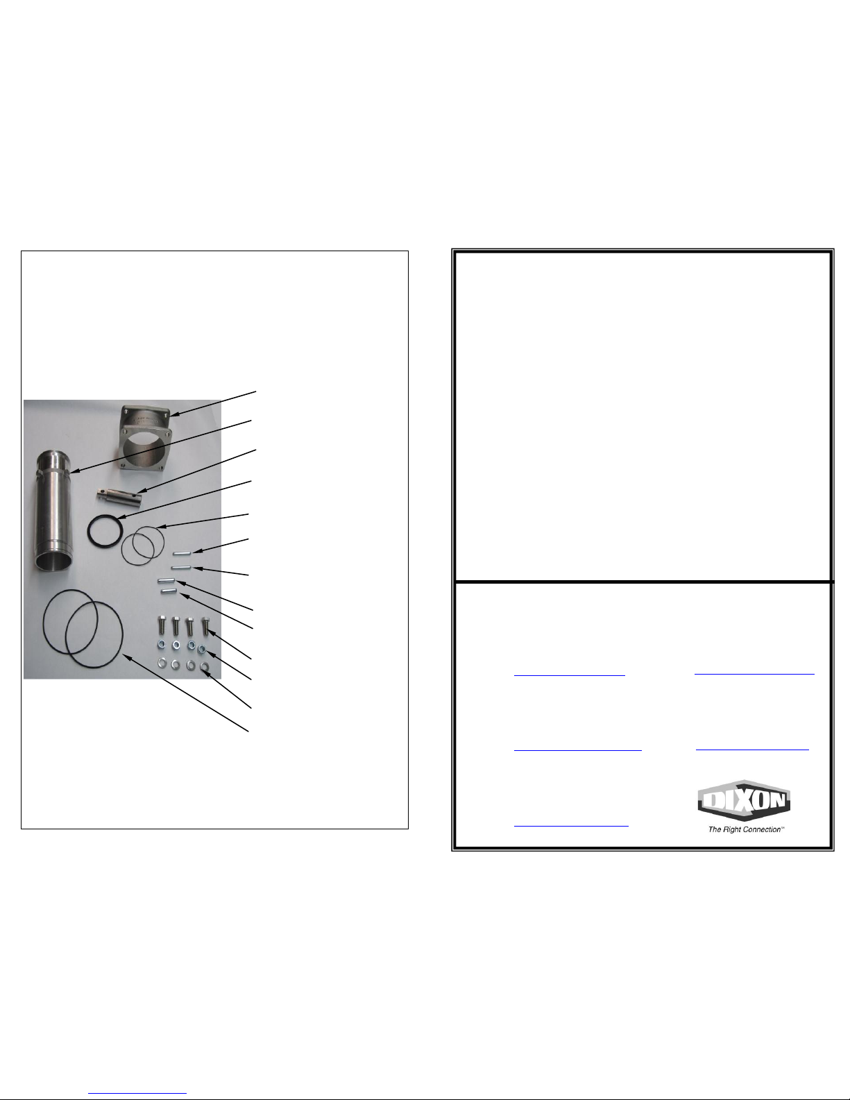
Materials included in Extension Kits
090081 R8
1 Pc Extension 3”
1 Pc Center Tube
(6400EXT only)
1 Pc Shaft Extension
1 Pc U-Cup 3.12” x 2.75” x
1/8” (6400EXT only)
2 Pc’s O-Ring 2.75”
1 Pc Pin 1/4” X 1-1/8”
(Elbow 6000)
1 Pc Pin 1/4” x 1-3/8”
(Elbow 6000)
1 Pc Pin 5/16” x 1-¼”
1 Pc Pin 5/16” x 1”
4 Pc’s Bolts 3/8 x 1.5”
4 Pc’s Nuts 3/8
4 Pc’s Lock Washer 3/8”
2 P’s O-Ring 4.25” x .093”
Page 2
DISASSEMBLY OF DROP ELBOWS
1) Remove the four 3/8” bolts securing the elbow to the bottom assembly.
2) For 6200, 6400 & VR6200 Elbows
Remove the 3/8” NC Nylon Lock nut and nylon washer holding the
actuating arm in place. Separate the elbow from the bottom assembly.
For 6500 & VR6500 Elbows
Remove the 3 hex head bolts holding the arm pivot plate to the elbow
body.
3) Drive out the spring pin that holds the aluminum actuating arm to the
stainless steel stem. For the 6000 D-Handle elbow drive out the pin
holding the Bronze D-handle to the stainless steel stem.
Note:
For the 6400 co-axial elbows remove the center fluid tube by loosening
the set screw on the elbow. Remove tube and replace with longer tube,
new u-cap seal & 2 0-rings provided. Re-tighten set screw.
ASSEMBLY OF KIT TO DROP ELBOW
1) Install the stainless steel extension by sliding it over the existing stem
and driving the original spring pin through the lined up holes.
2) For 6200, 6400, 6500, VR6200 and VR6500 side link elbows, attach the
actuator arm to the stainless steel extension using the supplied
5/16” X 1” pin.
3) For the 6000 D-handle type elbows, attach handle to the stainless steel
extension with the supplied ¼” X 1 1/8” pin.
4) Place the 3” extension casting over the bottom with the flat flange on the
bottom, insuring the 4.25” body O-ring is in place (included in kit). Using
the 3/8” x 1.5” Bolts & lock washers included in the extension kit, attach
the extension to the bottom casting.
5) Place the other 4.25” body O-ring (included in the kit) on the extension
casting. Using the original 3/8” Bolts and the supplied Nuts & original
lock washers secure the elbow to the top.
6) For the 6200 and 6400 side link elbows, place actuator arm on stud on
elbow. Replace nylon washer and tighten lock nut.
0
090081 R8
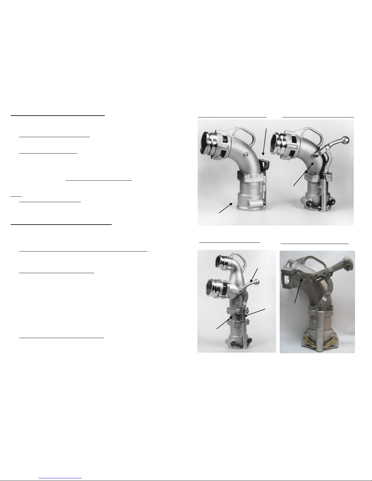
6400 Co-Axial Drop Elbow
Extension Kit Installed
6000 D-Handle Drop Elbow
6200 Side Lever Drop Elbow
Actuator Arm
SS Stem
Extension
Extension
Casting
Lock Nut
D Handle
Bottom Assembly
Arm pivot
plate
6500 Side Lever Drop Elbow
Page 3

Matériaux inclus dans la trousse d’extension
Extension de 3”
Tube central (coude 6400)
Arbre d’extension
U-Cup 3.12” x 2.75” x
1/8” Joint torique 2.75”
Goupille cylindrique 1/4” X 11/8” (Coude 6000)
Goupille cylindrique 1/4” x 1-
3/8” (Coude 6000)
Goupille cylindrique 5/16” X
1- 1/4”
Goupille cylindrique 5/16” X 1”
Vis 3/8 X 1.5”
3/8 NC écrou
Rondelle 3/8”
Joint torique 4.25” x .093”
Installation & Mode d’emploi
pour
TROUSSE D’EXTENSION POUR
LES COUDES BAYCO
Numéro des pièces
6000EXT & 6400EXT
Pour vente & service contactez
E-U:
Dixon Bayco USA
Chestertown, Maryland
Téléphone: 410-778-2000
Fax: 410-778-4702
Sans frais: 800-355-1991
E-mail: dixonbayco@dixonvalve.com
www.dixonbayco.com
Mexique:
Dixva, S. de R.L. de C.V.
Monterrey, N.L
Téléphone: 01-800-00-DIXON (34966)
Fax: 01-81-8354-8197
E-mail: contactenos@dixonvalve.com.mx
www.dixonvalve.com
Asie et Pacifique:
Dixon (Asia Pacific) Pty Ltd
Wingfield, South Australia
Téléphone: +61 8 8202 6000
Fax: +61 8 8202 6099
E-mail: enquiries@dixonvalve.com.au
www.dixonvalve.com.au
Canada:
Dixon Group Canada Limited
Innisfil (Barrie), Ontario
Téléphone: 705-436-1125
Fax: 705-436-6251
Sans frais: 877-963-4966
E-mail: isales@dixongroupcanada.com
www.dixongroupcanada.com
Europe:
Dixon Group Europe Ltd
Preston, England
Téléphone: +44 (0)1772 323529
Fax: +44 (0)1772 314664
E-mail: enquiries@dixoneurope.co.uk
www.dixoneurope.co.uk
090081(fr) R8
Page 4

DEASSEMBLAGE DES COUDES DE DÉCHARGEMENTS
1) Retirez les quatre boulons 3/8’’ qui sécurisent le coude à l’adaptateur inférieur.
2) Pour les coudes 6200, 6400 & VR6200. Retirez l’écrou de verrouillage 3/8’’ de
nylon NC et la rondelle de nylon qui garde les bras de commande en place.
Séparez le coude de l’adaptateur inférieur.
Pour les coudes 6500 & VR6500. Retirez les 3 vis à tête hexagonale qui
maintienne la plaque de pivotement du bras sur le corps du coude
3) Retirez la goupille à ressort qui retient les bras d’aluminium à la tige d’acier
inoxydable. Pour le coude à manche –D 6000, retirez la goupille qui tient le manche –
D de bronze contre la tige d’acier inoxydable.
Note:
Pour les coudes coaxiaux 6400, retirez le tube de fluide centrale en desserrant
les vis en place sur le coude. Retirez le tube et remplacez-le avec le tube plus allongé
qui est inclus dans la trousse. Remettez les vis et serrez-les.
TROUSSE D’ASSEMBLEMENT POUR LES COUDES DE
DÉCHARGEMENTS
1) Installez l’extension d’acier inoxydable en la glissant sur la tige en place et en
forçant la goupille à ressort à travers les trous alignés
2) Pour les coudes à leviers de coté 6200, 6400,6500, VR6200 et VR6500, attachez
le bras de commande à l’extension d’acier inoxydable en utilisant la goupille 5/16’’ X
1’’ fournie.
3) Pour le coude 6000 à manche style –D, attachez le manche à l’extension d’acier
inoxydable en utilisant la goupille 1/4" X 1 1/8" fournie.
4) Placez le moulage d’extension de 3’’ au-dessus de la partie inférieure avec la bride
plate au-dessous, assurez-vous que le joint torique original 4.25" soit en place. En
utilisant les vis 3/8’’ X 1.5" incluses dans la trousse d’extension, attachez le moulage
5) Installez le joint torique qui est inclus avec la trousse d’extension, En utilisant les
vis originales de 3/8’’ et les boulons et rondelles fournis, sécurisez le coude à la partie
supérieure.
6) Pour les coudes à levier de coté 6200 et 6400, placez le bras de commande sur le
goujon du coude. Remplacez la rondelle en nylon et serrer l’écrou de blocage.
Coude à levier de coté 6200
Coude de déchargement avec
Manche- D 6000
Coude coaxial
6400 Trousse d’extension installé
Coude à levier de côté 6500
Bras de
commande
Tige d’extension
d’acier inoxydable
Extension
du
Moulage
Bras pour plaque
pivotante
090081(fr) R8
Manche-D
Partie inférieure
Écrou de blocage
 Loading...