

Page 1
INSTALLATION & OPERATING
INSTRUCTIONS
BAYCO AIR INTERLOCK ELECTRICAL
5000S.....................Air Interlock Electrical Switch Kit
5000AISW.............Air Interlock W/ Electrical Switch Attached
SWITCH
Model Numbers
U S A:
Dixon Bayco USA
Chestertown, Maryland
Phone: 410-778-2000
Fax: 410-778-4702
Toll Free: 800-355-1991
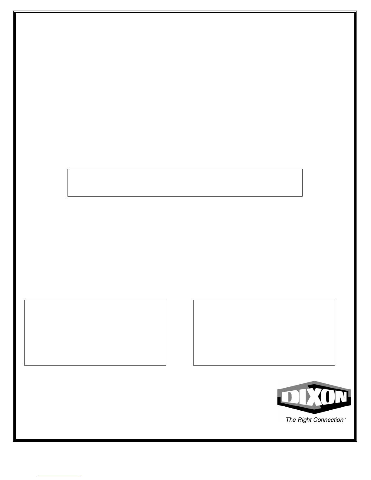
Dixon Bayco
A DIXON COMPANY
For Sales & Service Contact
CANADA:
Dixon Bayco Limited
Barrie, Ontario
Phone: 705-436-1125
Fax: 705-436-6251
Toll Free: 866-436-1125
40070PA Rev Oct 2003
1
Page 2
2 40070PA Rev Oct 2003
Page 3

Tools required for installation and part replacement
14mm open end wrench
3/4" open end wrench
INSTALLATION
CAUTION! SAFETY GLASSES MUST BE WORN DURING INSTALLATION
AND SERVICE.
CAUTION! BRASS END PLUG IS RESTRAINING A COMPRESSION
SPRING. ENSURE THAT YOU HAVE A FIRM GRIP ON THE
BRASS END PLUG BEFORE REMOVING
3 40070PA Rev Oct 2003
Page 4

ASSEMBLY
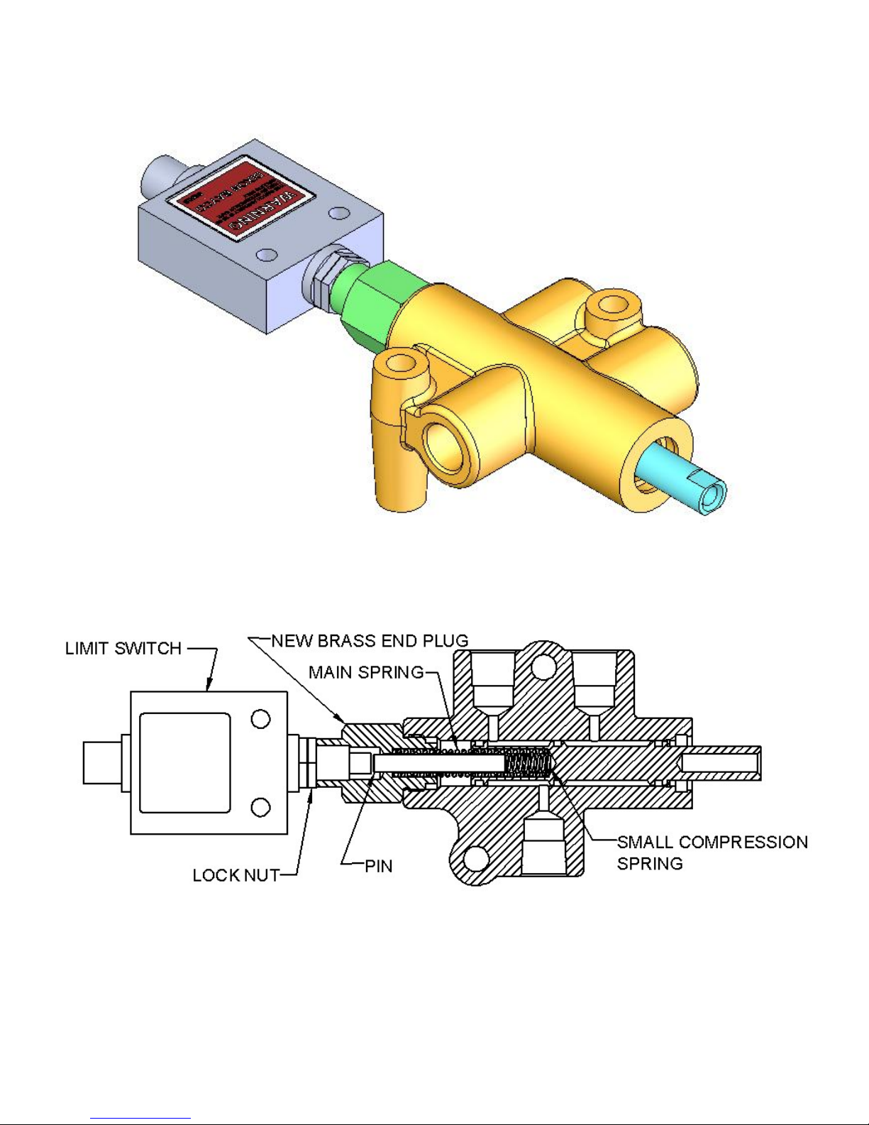
1. Using the 3/4" open-end wrench, remove the brass end plug from the existing Dixon Bayco Air
interlock valve. Hold the end plug firmly to prevent the spring from ejecting the plug from your
hand.
2. Leave the main spring installed inside the plunger. You may discard the brass end plug.
3. Install the new brass end plug from the kit. This is accomplished by compressing the main
spring while tightening the new end plug in place.
4. From the kit bag, place the small compression spring through the hole in the new brass end
plug until it slides down the inside of the main spring.
5. From the kit bag, place the pin through the hole in the new brass end plug until it slide s down
the inside of the main spring.
6. Retrieve the limit switch from the kit bag. Insure that the two lock nuts are installed and are
threaded against the body.
7. Install the limit switch into the new brass end plug as far as it will go. Do not over tighten.
8. You can back the limit switch off a maximum of 1/2 turn to orient the switch the way you like it.
9. Secure the switch by tightening one of the jam nuts (using the 14mm wrench) against the brass
end plug.
10. Connect the wire cable to the limit switch by aligning the notch in the wire plug to the projection
in the limit switch. Tighten the collar of the wire cable to secure it to the limit switch
11. Connect the brown and white wires of the cable to the AUX port of the on board monitor.
12. Cut off the blue and black wires
DIXON BAYCO WARRANTY
For Warranty Information, please refer to the inside back cover of the latest Dixon Catalogue.
4 40070PA Rev Oct 2003
 Loading...