

Page 1
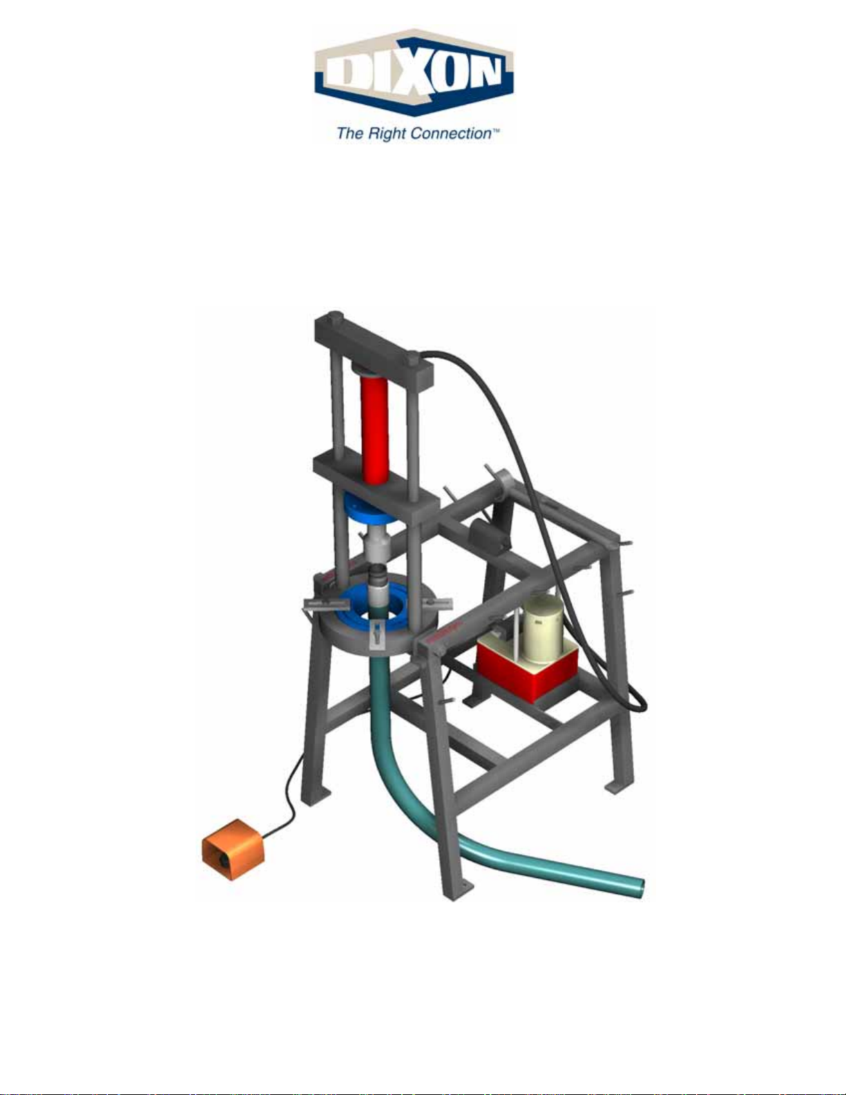
25 Ton Ram Operating Instructions
Section 4
External Swaging of Cam & Groove
Dixon Valve & Coupling Company
800 High Street • Chestertown, MD 21620
ph: 800•355•1991 fax: 800 •283•4966
www.dixonvalve.com
Page 2
25 Ton Ram Instruction Manual Externally Swaged Cam & Groove
Before you begin, make sure the ram is fully retracted, and remove the 25PUSH400 (also referred
to as the pusher hat) from the main pusher plate, if
installed on the ram.
Insert Die Holders into the Die Bed Plate as follows:
a) DH9-004 - Master Die Holder to hold all
of the other die holders.
b)DH9-004-1 - Die Holder for 4” I.D.
hoses only.
c) DH6-003 - Die Holder for 1 1/4” - 3” I.D.
hose dies (fits into DH9-004).
d)DH3-001 - Die Holder for 1/4” - 1” I.D.
hose dies (DH6-003 and DH9-004 also required).
Secure the Die Holders with the tie down bars supplied.
1
2
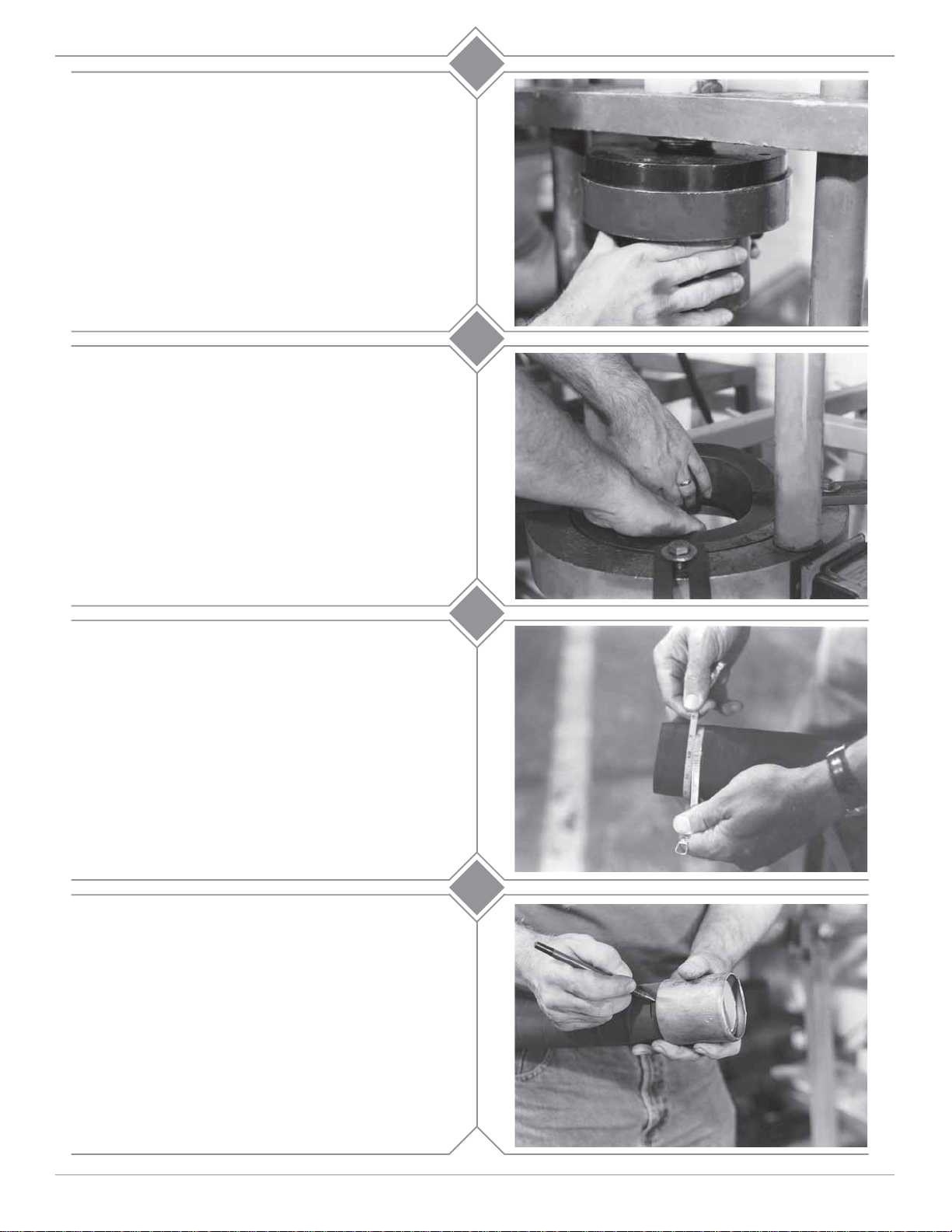
Accurately measure the hose O.D. with a diameter tape.
Each end of the hose should be measured to guarantee
the correct ferrule and die selection.
Select the proper ferrule and die based upon the hose
free O.D. just measured, from the die chart.
Make sure the hose end is cut square. If the hose is to
be static grounded, follow hose manufacturers procedure for proper static grounding.
Measure the collar thickness of the stem. Slide the
ferrule onto the hose. Place a mark on the hose at the
end of the ferrule. Move the ferrule from the mark
just made towards the end of the hose the distance of
the collar thickness just measured. Place a second
mark on the hose at the end of the ferrule.
3
4
customer service 800•355•1991
1Section 4
Page 3
25 Ton Ram Instruction Manual Externally Swaged Cam & Groove
Note : When using the Notched S tem and ferrule
system these guidelines
A.Before stem insertion, assemble the ferrule onto the stem
by sliding the turned over portion of the ferrule past the
notched sections of the stem collar. Rotate the ferrule 90°
(1/4 turn).
B. Before starting the swaging process, make sure that the
turned over portion of the ferrule and the collar are fully
engaged.
C. For “C” style couplings (requiring spacer rings), make
sure that the two ring halves meet over the turned over
portion of the ferrule which should be under the cam arms.
must be followed:
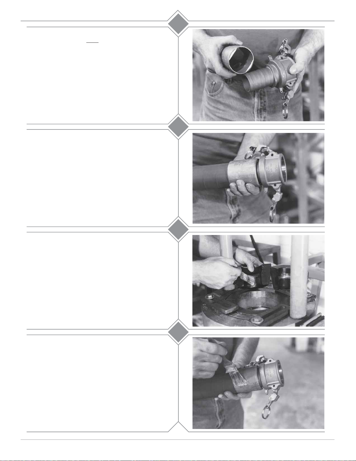
Lubricate the Hose I.D. and the O.D. of the
coupling shank with Dixon lubricant or equivalent.
Insert the Cam and Groove fitting with ferrule onto the
hose until the ferrule is even with the mark closest to
the hose end. This is the second mark made on the hose.
5a
5b
For “C” Style couplings requiring spacer rings:
a. Lubricate the inside of the die halves with
Crisco® (recommended) or a high viscosity
oil or heavy duty grease.
b. Lubricate the outside of the ferrule with
Crisco® (recommended) or a high viscosity oil
or heavy duty grease.
6a
6b
customer service 800•355•1991
2Section 4
Page 4

25 Ton Ram Instruction Manual Externally Swaged Cam & Groove
c. Release the cam arms.
d. Remove the gasket from the coupler.
6c
6d
e. Bring the hose and coupling assembly up
through the base of the die bed.
Note: One or both cam arms may close going
through the die bed. If this happens, release
the cam arms.
f. Put the selected die into the die bed.
g. Put the spacer rings between the ferrule and
coupler head, making sure that the two
ring halves meet over the turned over
portion of the ferrule.
* Note: Future “C” style couplings may not
require spacer rings. In those instances,
eliminate Step 6g.
6e
6f
6g
customer service 800•355•1991
3Section 4
Page 5

25 Ton Ram Instruction Manual Externally Swaged Cam & Groove
h. Insert the proper pusher into the coupler
(reference the chart at the end of this section
for proper pusher selection).
i. Bring the assembly down into the opening of
the die.
j. Jog the ram cylinder down until it meets the
pusher.
6h
6i
6j
Note: Check spacer rings for proper positioning.
k. Hold the “on” button down (or depress the
foot pedal) and continue the swage process
until the spacer rings begin to enter the die.
Release the “on” button (or foot pedal).
Do not let the spacer rings enter the die!
6k
6l-n
l. Lift the hose assembly up and remove the
pusher, spacer rings and the die halves from
the die bed.
m. Lower the hose through the die bed and wipe
off the excess lubricant.
n. Re-install the gasket.
customer service 800•355•1991
4Section 4
Page 6

25 Ton Ram Instruction Manual Externally Swaged Cam & Groove
For “C” Style couplings not requiring spacer rings,
perform Steps 6a through 6f and 6h
through 6n.
Step 6k hold the “on” button down (or depress the
foot pedal) and continue the swage process until the
top of the ferrule has passed the top of the dies.
Don’t let the locking ear on the
coupler touch the die.
For “E” Style couplings follow steps 1-5 then:
6
end
7a
a. Lubricate the inside of the die halves with
Crisco® (recommended) or a high viscosity
oil or heavy duty grease.
b. Lubricate the outside of the ferrule with
Crisco® (recommended) or a high viscosity
oil or heavy duty grease.
7b
7c-d
c. Bring the hose and coupling assembly up
through the base of the die bed.
d. Put the selected die into the die bed.
customer service 800•355•1991
5Section 4
Page 7

25 Ton Ram Instruction Manual Externally Swaged Cam & Groove
e. Install the proper pusher over the adapter
(reference the chart at the end of this section
for proper pusher selection).
f. Bring the assembly down into the opening
of the die.
g. Jog the ram cylinder down until it meets the
pusher. Make sure that the cylinder plate
contacts the pusher flush.
7e-f
7g
h. Holding the hose and coupling up against the
pusher hold the “on” button down (or depress
the foot pedal) until the ferrule enters the
opening of the die. Once the ferrule has entered
the die and started to be reduced (approximately
1/3 of the way) it will no longer need the
operator to keep it seated into the pusher.
Continue the swage process until the pusher
meets the die face. Release the “on” button
(or foot pedal).
i. Lift the hose assembly up and remove the
pusher, and die halves from the die bed.
Note: If the gauge reads 10,000 PSI before swaging is
complete, stop. The ferrule or die used for that hose end
may be incorrect. Contact Dixon for further assistance.
7h
7i
customer service 800•355•1991
6Section 4
Page 8

25 Ton Ram Instruction Manual Externally Swaged Cam & Groove
Pushers and Spacer Rings For Cam & Gr oove
Size Description Part Number
1”
1 1/2”
2”
3”
4”
Type “E” Pusher
Type “C” Pusher
Spacer Ring
Type “E” Pusher
Type “C” Pusher
Spacer Ring
Type “E” Pusher
Type “C” Pusher
Spacer Ring
Type “E” Pusher
Type “C” Pusher
Spacer Ring
Type “E” Pusher
Type “C” Pusher
Spacer Ring
RE100PUSH
RC100PUSH
100CGSPACE
RE150PUSH
RC150PUSH (2 pieces)
150CGSPACE
D011-018
D011-018
200CGSPACE
25PUSH300E
D011-018
300CGSPACE
25PUSH400E
25PUSH400C
400CGSPACE
Note: Spacer Rings are to be used with Type “C” Couplings ONLY.
DO NOT use Spacer Rings with Type “E” Couplings, or
bodily injury may result.
Dixon Valve and Coupling Company recommends that all
hose assemblies be tested as recommended by the Rubber Manufacturers Association.
customer service 800•355•1991
7Section 4
 Loading...