

Page 1
25 Ton Ram Operating Instructions
Section 3
External Swaging of RSTxxxNOS Stems
Dixon Valve & Coupling Company
800 High Street • Chestertown, MD 21620
ph: 800•355•1991 fax: 800•283•4966
www.dixonvalve.com
Page 2
25 T on Ram Instruction Manual Externally Swaged RSTxxxNOS Stems
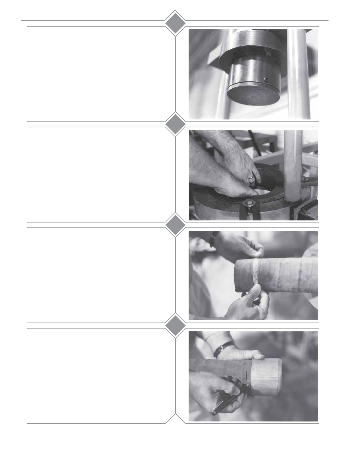
Before you begin, make sure the ram is fully
retracted. Install 25PUSH400 (also referred to as
the pusher hat) onto the main pusher plate. Install
the MISCPUSH into the 25PUSH400 and secure
with set screw.
Insert Die Holders into the Die Bed Plate as
follows:
a) DH9-004 - Die holder. This is necessary to
hold all of the other die holders.
b) DH6-003 - Die holder for 1 1/4” - 3” I.D.
hose dies.
1
2
Secure the die holders with the keeper plates supplied.
Accurately measure the hose O.D. with a diameter
tape. Each end of the hose should be measured to
guarantee the correct ferrule and die selection.
Select the correct ferrule and die based upon the hose
free O.D. just measured, from the die chart.
Make sure the hose end is cut square. If the hose is to
be static grounded, follow hose manufacturers
procedure for proper static grounding.
Slide the ferrule onto the hose. Place a mark on the
hose at the end of the ferrule. Move the ferrule 1/8”
from the mark just made towards the end of the hose.
Place a second mark on the hose at the end of the
ferrule.
3
4
customer service 800•355•1991
1Section 3
Page 3

25 T on Ram Instruction Manual Externally Swaged RSTxxxNOS Stems
Lubricate the O.D. of the stem and the I.D. of the hose
with Dixon lubricant or equivalent.
Insert the end of the fitting into hose. Assemble ferrule
onto stem by sliding turned over portion of ferrule past
notched section of the stem collar. Rotate the ferrule
90° (1/4 turn). With ferrule and stem engaged, continue
installing stem until ferrule reaches the second mark
made on the hose.
Lubricate the outside of the ferrule with Crisco®
(recommended) or a high viscosity oil or heavy duty
grease.
5
6a
Lubricate the I.D. of die halves with Crisco® (recommended) or a high viscosity oil or heavy duty grease.
Insert the hose with fittings through the bottom of
the ram (between the die holders) to allow enough
room to install the die halves into the die holder.
6b
7
customer service 800•355•1991
2Section 3
Page 4

25 T on Ram Instruction Manual Externally Swaged RSTxxxNOS Stems
Install spacer ring over threads of stem and rest on top
of ferrule.
Install the proper pusher onto the stem. (reference the
chart for proper pusher selection.)
8
9
“Jog” the ram by quickly depressing and releasing the
“on” button on the remote control switch, (or by
depressing the foot pedal) until the ferrule enters the
opening of the die. Go slowly as the ferrule enters the
die, making sure that the end of the ferrule does not
contact the face of the die.
Make sure that the stem and ferrule are forced securely
against the pusher until the swaging process has begun.
To complete the swaging process, depress and hold
the “on” switch of the remote control unit (or depress
the foot pedal). Once the ferrule has entered the die
and starts to be reduced (approximately 1/3 of the
way), it will no longer need the operator to keep
it seated into the pusher. Continue the swage until the
pusher meets the die.
10
11
Note: The spacer ring will enter the die.
customer service 800•355•1991
3Section 3
Page 5

25 T on Ram Instruction Manual Externally Swaged RSTxxxNOS Stems
Lift the hose assembly up and remove the pusher,
spacer ring and die halves from the
die bed. Remove excess lubricant.
Note: If gauge reads 10,000 PSI before swaging is
complete, than the ferrule or die used for that hose
end may be incorrect.
Contact Dixon for further assistance.
Pushers for RSTxxxNOS Stems
Size Part Number
12
1 1/2”
2”
3”
RE150PUSH
D011-018
RE300PUSH
Dixon Valve and Coupling Company recommends that all
hose assemblies be tested as recommended by the Rubber Manufacturers Association.
customer service 800•355•1991
4Section 3
 Loading...